Question 33 OSE02 - Assistant Engineer - OSV
The offshore supply vessel to which you are assigned has main engines fitted with intake and exhaust systems as shown in the illustration. What statement is true concerning the turbocharger charge air discharge arrangements? Illustration MO-0177
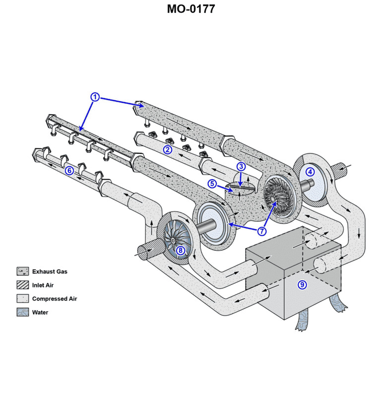
The Correct Answer is A **Explanation for Option A (Correct):** Option A is correct because the illustration (MO-0177, which typically depicts a V-type marine or industrial diesel engine with dual turbochargers) shows a **cross-bank charging** arrangement, often used for packaging and efficiency reasons, especially in V-type engines. In this configuration: * The exhaust gases from the left cylinder bank drive the turbocharger located on the left side of the engine. The compressed air (charge air) produced by this left turbocharger is then routed across the top of the engine (or through a crossover duct) to supply the intake manifold of the **right cylinder bank**. * Similarly, the exhaust gases from the right cylinder bank drive the turbocharger located on the right side. The compressed air from this right turbocharger is routed across the engine to supply the intake manifold of the **left cylinder bank**. This setup ensures each cylinder bank receives compressed air from the opposite side's turbocharger, optimizing air flow and sometimes simplifying the plumbing around other engine components. **Explanation of Incorrect Options:** * **B) It is not possible to determine the turbocharger charge air discharge arrangements in this particular drawing.** This is incorrect. Standard industrial or marine diesel engine diagrams, like MO-0177 (often representing known V-engine designs such as some EMD or large CAT models), clearly show the path of the charge air piping (which typically includes an intercooler/aftercooler). The visible routing confirms a cross-bank flow pattern. * **C) The left side turbocharger discharges charge air to both cylinder banks, and the right side turbocharger discharges charge air to both cylinder banks.** This describes a parallel charging system where both turbochargers feed a common header supplying both banks, or potentially a sequential system. While some large V-engines use dual systems feeding a common plenum, the design shown in MO-0177 specifically utilizes dedicated crossover piping for cross-bank charging, meaning the charge air streams generally remain separate until they reach the opposite manifold. * **D) The left side turbocharger discharges charge air to the left cylinder bank, and the right side turbocharger discharges charge air to the right cylinder bank.** This describes a straight-bank (or dedicated) charging arrangement, where each turbocharger feeds its own corresponding cylinder bank. If this were true, the plumbing would be much simpler and would not require the crossover ducting visible in the specific illustration for this question.
Pass Your Coast Guard Licensing Exams!
Study offline, track your progress, and simulate real exams with the Coast Guard Exams app