Question 59 DDE01 - Designated Duty Engineer - Unlimited HP
The winch drive engine on the harbor tug to which you are assigned is fitted with a Roots-type blower as shown in the illustration. What statement is true concerning this blower? Illustration MO-0082
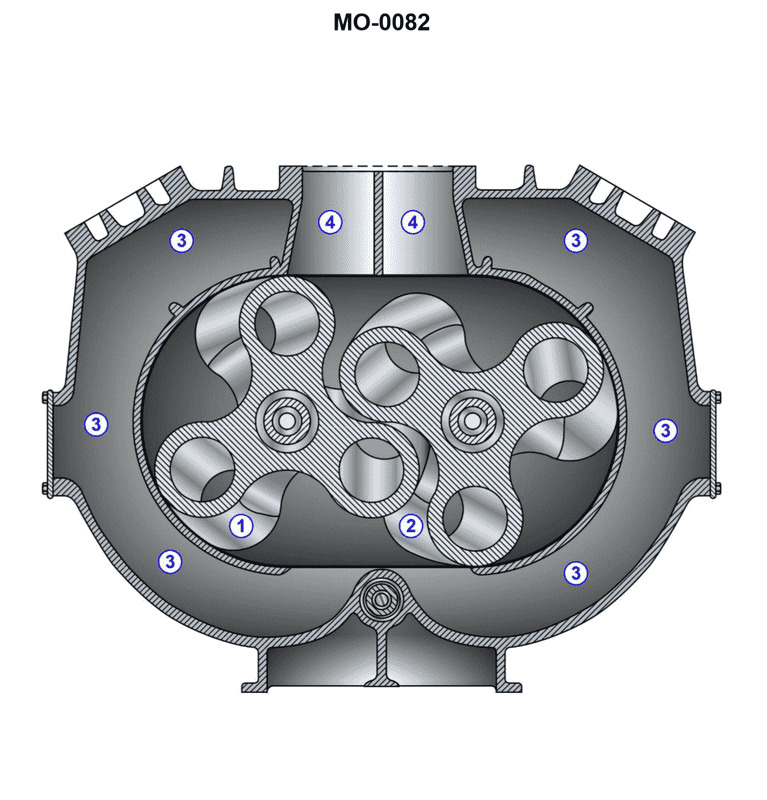
The Correct Answer is C ### Explanation of Why Option C is Correct A Roots-type blower is a positive displacement machine used here to supply scavenging or supercharging air to the engine. It consists of two intermeshing rotors (lobes) that rotate in opposite directions inside a fixed casing. 1. **Flow Direction (Suction and Discharge):** In the illustration of a functioning blower, air must be drawn in at the inlet (suction) and forced out at the outlet (discharge). Based on the standard convention for a marine engine blower configuration, **Area "4" is the Suction passage (Inlet)** where air is drawn in, and **Area "3" is the Discharge passage (Outlet)** where the air is compressed and forced into the engine intake manifold. 2. **Rotor Rotation:** To move the air trapped in the pockets from the inlet (4) down toward the outlet (3), the rotors must sweep the air along the casing walls in that direction. * **Rotor 1 (left side)** must turn away from the casing walls at the bottom and toward the casing walls at the top. This means Rotor 1 rotates **Counterclockwise (CCW)**. * **Rotor 2 (right side)** must turn away from the casing walls at the bottom and toward the casing walls at the top. This means Rotor 2 rotates **Clockwise (CW)**. Option C correctly identifies both the rotational directions required to achieve the necessary air movement (Rotor 1 CCW, Rotor 2 CW) and the function of the specific passages (3 is discharge, 4 is suction). *** ### Explanation of Why the Other Options are Incorrect **A) Rotor "1" turns clockwise, and rotor "2" turns counterclockwise. Area "3" is the discharge passage, and area "4" is the suction passage.** This option correctly identifies the suction and discharge areas (3 discharge, 4 suction) but incorrectly defines the rotor rotation. If the rotors turned in these directions (R1 CW, R2 CCW), the air would be blocked or, if possible, pushed back toward the inlet, preventing effective air scavenging/supercharging. **B) Rotor "1" turns counterclockwise, and rotor "2" turns clockwise. Area "3" is the suction passage, and area "4" is the discharge passage.** This option correctly describes the rotational direction (R1 CCW, R2 CW) needed for the blower to operate, but it incorrectly reverses the function of the passages. This rotation forces air from 4 to 3, meaning 4 must be the suction and 3 must be the discharge. **D) Rotor "1" turns clockwise, and rotor "2" turns counterclockwise. Area "3" is the suction passage, and area "4" is the discharge passage.** This option is incorrect on two counts: the rotational direction (R1 CW, R2 CCW) is wrong for the intended function, and the designation of the suction and discharge passages is reversed.
Pass Your Coast Guard Licensing Exams!
Study offline, track your progress, and simulate real exams with the Coast Guard Exams app