Question 26 OSE02 - Assistant Engineer - OSV
The platform construction support vessel to which you are assigned has a deck winch drive engine fitted with fuel injectors with the operating principle as shown in the illustration. In figure "A" which plunger travel position corresponds to when fuel injection begins? Illustration MO-0144
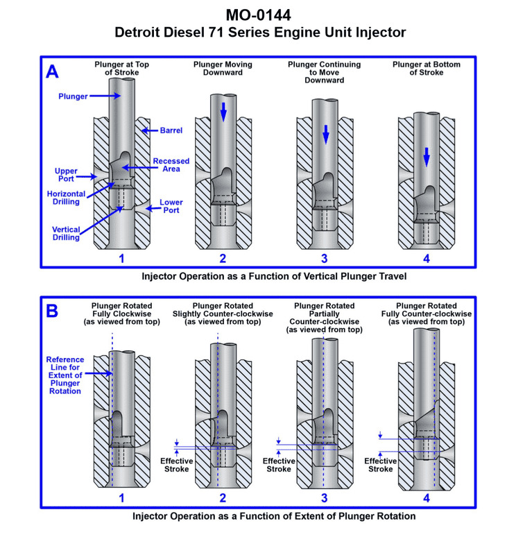
The Correct Answer is B. ### Explanation of Correct Option (B) - Position 2 The illustration (MO-0144, representing a jerk-type fuel injection pump) typically shows the relationship between the pump plunger's position and the fuel ports (spill port and inlet port). Fuel injection begins when the rising edge of the plunger's helix or control edge covers the inlet/suction port (also known as the filling or supply port). * **Position 1:** The plunger is at the bottom of its stroke (Bottom Dead Center - BDC). Both the inlet port and the spill port are open, allowing the fuel gallery to fill the barrel above the plunger. * **Position 2:** The plunger has risen sufficiently so that its upper edge (the effective pumping edge) has just covered the **inlet port**. At this exact point, the fuel trapped above the plunger becomes pressurized, and injection starts (assuming residual pressure is sufficient to lift the delivery valve). Therefore, Position 2 corresponds to the start of fuel injection. * **Position 3:** The plunger continues to rise, pressurizing and injecting fuel. In this position, the injection process is underway. * **Position 4:** The plunger's helix (or diagonal groove) aligns with the **spill port** (or bypass port). At this point, the high-pressure fuel escapes back into the low-pressure gallery, causing the pressure to drop suddenly, and injection ends (fuel cut-off). Position 2 marks the closure of the inlet port, which is the immediate action leading to the rapid pressure build-up necessary for injection to commence. ### Explanation of Incorrect Options * **A) 1:** Position 1 shows the plunger at BDC. Both ports are fully open, and fuel is simply filling the barrel. No compression or injection is occurring. * **C) 3:** Position 3 shows the injection process in progress, occurring after injection has already begun (at Position 2) and before injection ends (at Position 4). * **D) 4:** Position 4 shows the moment the effective stroke ends and fuel injection ceases (fuel spill/cut-off) because the relief groove uncovers the spill port, dropping the pressure.
Pass Your Coast Guard Licensing Exams!
Study offline, track your progress, and simulate real exams with the Coast Guard Exams app