Question 57 MODE01 - Chief MODU Engineer
An engine is equipped with the overspeed trip similar to that shown in the illustration. The throw out weight is designed to run at 900 RPM and trip out at 10% overspeed. However, the overspeed trip is currently activating at 930 RPM. In order to correct this problem, __________. Illustration MO-0101
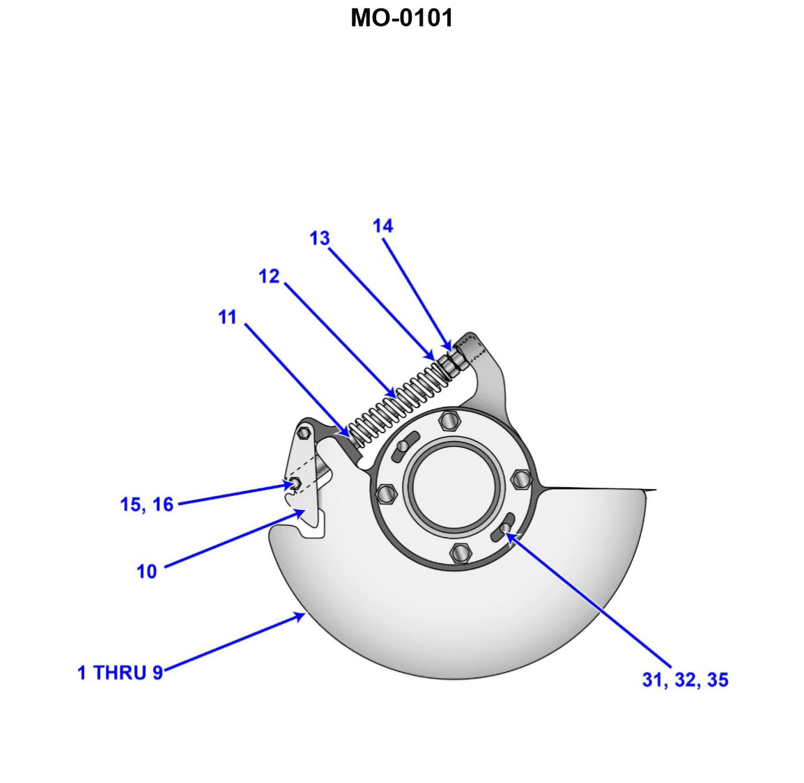
The Correct Answer is C ### Explanation for Option C (Correct Answer) The problem states that the desired tripping speed is 900 RPM + 10\% overspeed, which is $900 \times 1.10 = 990$ RPM. However, the governor is currently activating (tripping) at 930 RPM. This means the engine is tripping too early (at a lower speed than intended). The overspeed trip mechanism operates by balancing the centrifugal force generated by the throw-out weight (piece #10) against the opposing force exerted by the spring (piece #12). * **To trip later (at a higher RPM),** the centrifugal force required to overcome the spring must be greater. * **To increase the opposing force of the spring,** the compression on spring #12 must be increased. Increasing the spring compression requires the throw-out weight to spin faster (generate more centrifugal force) before it overcomes the spring tension and activates the trip mechanism. Therefore, increasing compression on spring #12 will raise the tripping speed from 930 RPM towards the desired 990 RPM. ### Explanation for Incorrect Options **A) decrease compression on spring #12:** Decreasing the spring compression would make it easier for the throw-out weight to move outward. This would lower the tripping speed even further below 930 RPM, worsening the current problem. **B) install a larger throw out weight piece #10:** A larger (heavier) throw-out weight generates more centrifugal force at any given speed ($F_c \propto m$). Installing a larger weight would cause the trip to activate at an even lower RPM than 930 RPM, worsening the problem. (Alternatively, if the desired speed was maintained, a lighter weight would be needed, not a larger one.) **D) change the angle of the operating face by machining piece #10:** Machining the angle of the operating face changes the mechanical leverage or the geometry of how the weight acts against the trip linkage. While this is a design parameter, changing the angle is usually a drastic measure related to the overall sensitivity curve or stroke length, not the primary adjustment for correcting a simple overspeed set point error. The standard and correct method for adjusting the trip speed set point is always to adjust the spring tension (compression).
Pass Your Coast Guard Licensing Exams!
Study offline, track your progress, and simulate real exams with the Coast Guard Exams app