Question 62 DDE01 - Designated Duty Engineer - Unlimited HP
The steam generating plant on your articulated tug-barge unit is of the forced-circulation type. Which figure of the illustration represents a steam generator or boiler of this type? Illustration MO-0197
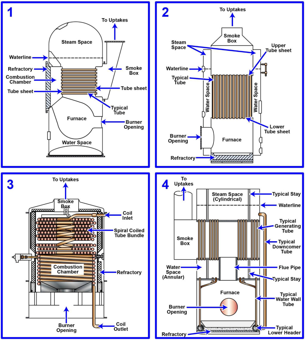
The Correct Answer is C ### Explanation for Option C (3) Figure 3 typically represents a steam generator utilizing **forced circulation**. In this type of boiler, the feedwater is circulated through the heating tubes (risers) by means of a high-pressure pump, rather than relying solely on the difference in density between the hot steam/water mixture and the colder water (natural circulation). Forced-circulation boilers (such as the La Mont or Benson types) are often used in modern installations, including articulated tug-barge (ATB) units, because they allow for: 1. Higher operating pressures. 2. More compact designs. 3. Precise control over water flow to prevent tube overheating. The schematic representation of Figure 3 highlights the use of this circulation pump, which is the defining characteristic distinguishing it from naturally circulating designs. ### Explanation for Other Options **A) 1:** Figure 1 commonly represents a **natural circulation water-tube boiler** (often a D-type or two-drum design). These boilers rely on the density difference between the water in the downcomers and the steam/water mixture in the risers to achieve circulation. This is the most common boiler type but is not a forced-circulation system. **B) 2:** Figure 2 often depicts a variation of a natural circulation boiler, sometimes a very old design (like a header boiler) or, less commonly, a schematic of a different power plant component (like a superheater or economizer separate from the main steam path). Regardless, it typically lacks the defining circulation pump of the forced-circulation type. **D) 4:** Figure 4 usually represents a component separate from the boiler circulation system, such as a firetube boiler (less common in modern marine applications) or potentially a heat exchanger or condenser schematic within the larger power plant loop. It does not illustrate the internal forced-circulation mechanism of a water-tube boiler.
Pass Your Coast Guard Licensing Exams!
Study offline, track your progress, and simulate real exams with the Coast Guard Exams app