Question 239General Subjects - Assistant Engineer
70% to passWhat is the normal direction of flow through the device shown in the illustration while operating in the processing mode? Illustration GS-0153
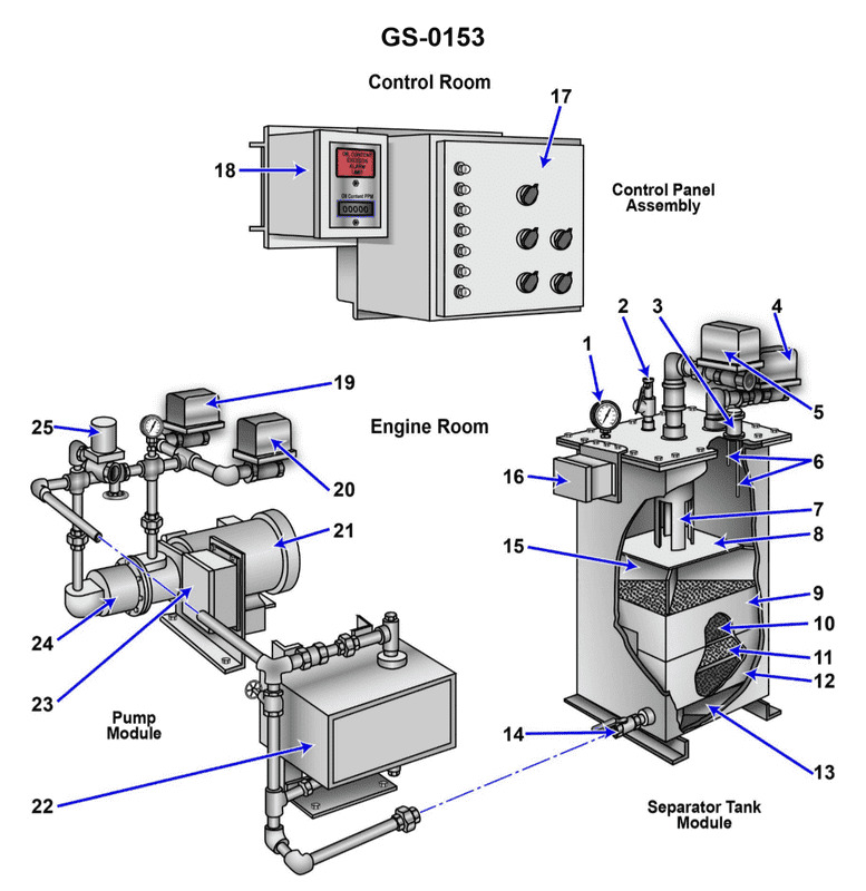
AThe oily-water mixture enters through the pressure control valve "2" and exits with the processed liquid through valve "14".
BThe oily-water mixture enters through valve "4" and exits as processed liquid through valve "14".
CThe oily-water mixture enters through valve "5" and exits the separator through valve "14" as processed liquid.
DThe oily-water mixture enters through valve "14" and exits with the processed liquid through valve "4".
AI Explanation
The correct answer is C. The oily-water mixture enters through valve "5" and exits the separator through valve "14" as processed liquid. This is the correct answer because the normal direction of flow through the device in the processing mode is from the inlet valve (valve "5") to the outlet valve (valve "14"). The oily-water mixture is fed into the separator through valve "5" and the processed liquid, with the oil removed, exits through valve "14". The other answer choices are incorrect because they do not accurately depict the normal direction of flow through the device. Options A, B, and D describe flow patterns that do not match the typical configuration and operation of this type of oily-water separator.
Related Questions
Q172:In application, which of the listed sealing devices is most similar to an O-ring... Q615:Under the federal regulations of 33 CFR Subchapter O, if a vessel equipped with ... Q225:What is meant by the term toughness as it applies to a material? Q564:For an analog electronic transmission system for instrumentation and control pur... Q593:Referring to the illustrated motor ship fresh water cooling system drawing, whic...
Ready to test your knowledge?
Take a General Subjects - Assistant Engineer Practice ExamOfficial Resources