Question 358Electricity & Electronics - QMED
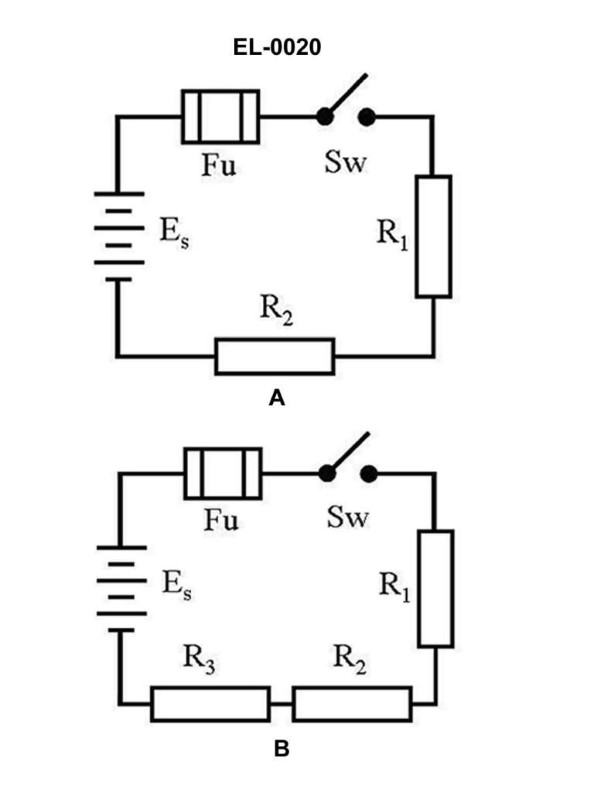
70% to passWhat is the voltage across 'R1' of figure "B" of the illustrated circuit with the switch closed if the applied voltage is 24 volts and resistance of R1 is 3 ohms, R2 is 4 ohms, and R3 is 5 ohms, respectively? Illustration EL-0020
A2 volts
B6 volts
C8 volts
D10 volts
AI Explanation
The correct answer is B) 6 volts. To find the voltage across R1, we can use the formula for voltage division: V1 = (R1 / (R1 + R2 + R3)) * Vapp, where V1 is the voltage across R1, R1 is the resistance of R1, R2 is the resistance of R2, R3 is the resistance of R3, and Vapp is the applied voltage. Plugging in the given values, we get: V1 = (3 / (3 + 4 + 5)) * 24 = 6 volts. The other options are incorrect because they do not correctly apply the voltage division formula to the given circuit and resistor values.
Related Questions
Q79:What will be the resulting current when a voltage of 442.7 VDC is applied to a r... Q451:Which of the illustrated safety disconnect switches represents a double-throw sw... Q349:Before touching a small capacitor connected to a de-energized circuit, or even o... Q285:In electronic circuitry, what does the abbreviation 'PCB' commonly represent? ... Q153:What controls rudder movement when the Operation Selector Switch shown in figure...
Ready to test your knowledge?
Take a Electricity & Electronics - QMED Practice ExamOfficial Resources