Question 222Electricity & Electronics - 1st Asst/Chief
70% to passIf the clock frequency input to the circuit shown in the illustration were 2 kHz, what would be indicated at the output of 'FF-3' at the Q3 output? Illustration EL-0087
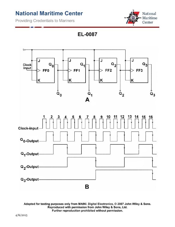
The correct answer is A) 125 Hz. In the circuit shown in the illustration EL-0087, the clock frequency input is 2 kHz. The circuit uses a series of flip-flops (FF-1, FF-2, FF-3) to divide the input frequency down. Each flip-flop divides the frequency by 2, so the output at the Q3 terminal of FF-3 will be 1/8th of the input frequency, which is 2 kHz / 8 = 250 Hz. The other options are incorrect because: B) 250 Hz is the output at the Q2 terminal of FF-2, not the Q3 terminal of FF-3; C) 500 Hz is the output at the Q1 terminal of FF-2, not the Q3 terminal of FF-3; and D) 1000 Hz is the output at the Q0 terminal of FF-1, not the Q3 terminal of FF-3.
Ready to test your knowledge?
Take a Electricity & Electronics - 1st Asst/Chief Practice ExamPass Your Coast Guard Licensing Exams!
Study offline, track your progress, and simulate real exams with the Coast Guard Exams app