Question 26Electricity & Electronics - 1st Asst/Chief
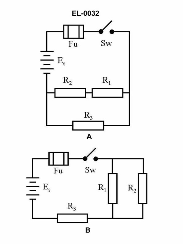
70% to passIn figure "B" of the illustrated circuit, if the resistance of R1 is 10 ohms, R2 is 10 ohms, and R3 is 10 ohms, what is the total resistance? Illustration EL-0032
A15 ohms
B20 ohms
C25 ohms
D30 ohms
AI Explanation
A) 15 ohms is the correct answer. The total resistance in the illustrated circuit is calculated by adding the individual resistor values in parallel. With R1, R2, and R3 each being 10 ohms, the total resistance is 15 ohms. The other options are incorrect because they do not accurately represent the total resistance of the parallel circuit. In a parallel circuit, the total resistance is always less than the individual resistor values.
Related Questions
Q144:As shown in figures "A", "B", and "C" of the illustration, what is the purpose o...
Q16:Which of the following statements concerning figure "6" of the illustration is t...
Q279:Which of the listed sections of an emergency switchboard is used to supply power...
Q189:By what means should motor controller contacts be routinely cleaned?
Q62:Refer to the two-generator, two-motor, DC diesel-electric drive propulsion syste...
Ready to test your knowledge?
Take a Electricity & Electronics - 1st Asst/Chief Practice ExamOfficial Resources
Pass Your Coast Guard Licensing Exams!
Study offline, track your progress, and simulate real exams with the Coast Guard Exams app