Question 433Electricity & Electronics - Assistant Engineer
70% to passIf coil 'R1-R2-R3' on the transmitter in figure "C" shown in the illustration is turned 30 degrees clockwise, how will the corresponding coils 'R1-R2-R3' on the receivers (indicators) respond? Illustration EL-0092
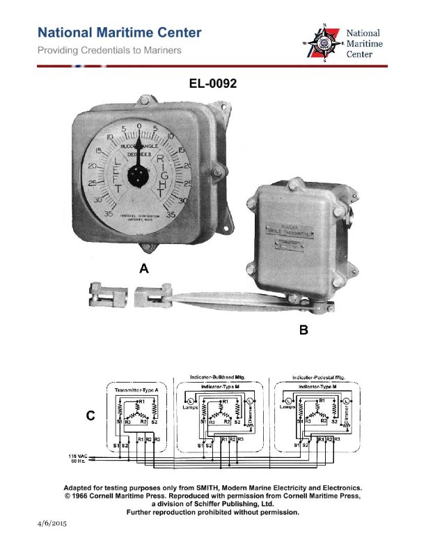
The correct answer is C) torque will cause them to align to the same position. When the coil 'R1-R2-R3' on the transmitter in figure "C" is turned 30 degrees clockwise, it creates a changing magnetic field. This changing magnetic field induces a current in the corresponding coils 'R1-R2-R3' on the receivers (indicators), which will experience a torque that aligns them to the same 30-degree clockwise position as the transmitter coil. This is the principle of electromagnetic induction and mutual alignment that allows remote position indication systems to function. The other options are incorrect because: A) the voltage received by the indicator coils is not directly affected by the turns ratio, but by the changing magnetic field; B) the voltage would not increase, but rather the coils would align to the same position; D) the receivers would not ring, but rather align to the transmitter position.
Ready to test your knowledge?
Take a Electricity & Electronics - Assistant Engineer Practice ExamPass Your Coast Guard Licensing Exams!
Study offline, track your progress, and simulate real exams with the Coast Guard Exams app