Question 70 QMED03 - Oiler
As shown in the illustration, what component would normally be installed at location "I"? Illustration MO-0231
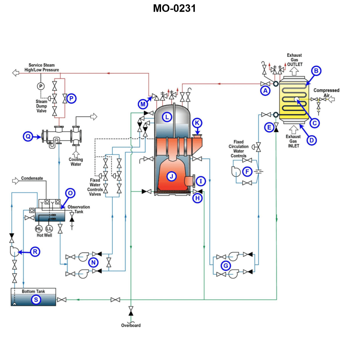
The Correct Answer is B **Explanation for B (Oil fired mechanical burner):** The location "I" (as referenced in illustration MO-0231, which typically depicts a marine or industrial watertube boiler setup) is positioned at the front wall (furnace front) of the boiler, directly interfacing with the combustion chamber (furnace). This specific location is where the fuel (in this case, oil) is introduced, atomized, and ignited to create the flame necessary for generating heat. Therefore, an **oil fired mechanical burner** (or register) is the component universally installed at this primary firing location. **Explanation for why other options are incorrect:** * **A) Boiler sootblower unit:** Sootblowers are installed to clean heat transfer surfaces (like superheaters, economizers, or convection tubes) typically located *inside* the gas passages, not directly at the furnace front for firing purposes. * **C) Flue gas smoke indicator:** This instrument is used to monitor the quality of the exhaust gases. It is installed in the stack or uptake (the path where the flue gases exit the boiler), far downstream from the combustion process location "I". * **D) Boiler water level indicator:** This gauge is mounted externally on the boiler drum (steam/water drum) to provide a visual indication of the water level. It is related to the steam generation cycle, not the firing process that occurs at the furnace front (Location "I").
Pass Your Coast Guard Licensing Exams!
Study offline, track your progress, and simulate real exams with the Coast Guard Exams app