Question 50 QMED01 - Junior Engineer
According to the illustrated diesel engine fuel treatment and fuel service systems schematic, what would be the appropriate valve configuration for operating the two heavy fuel oil purifiers in series? Illustration MO-0077
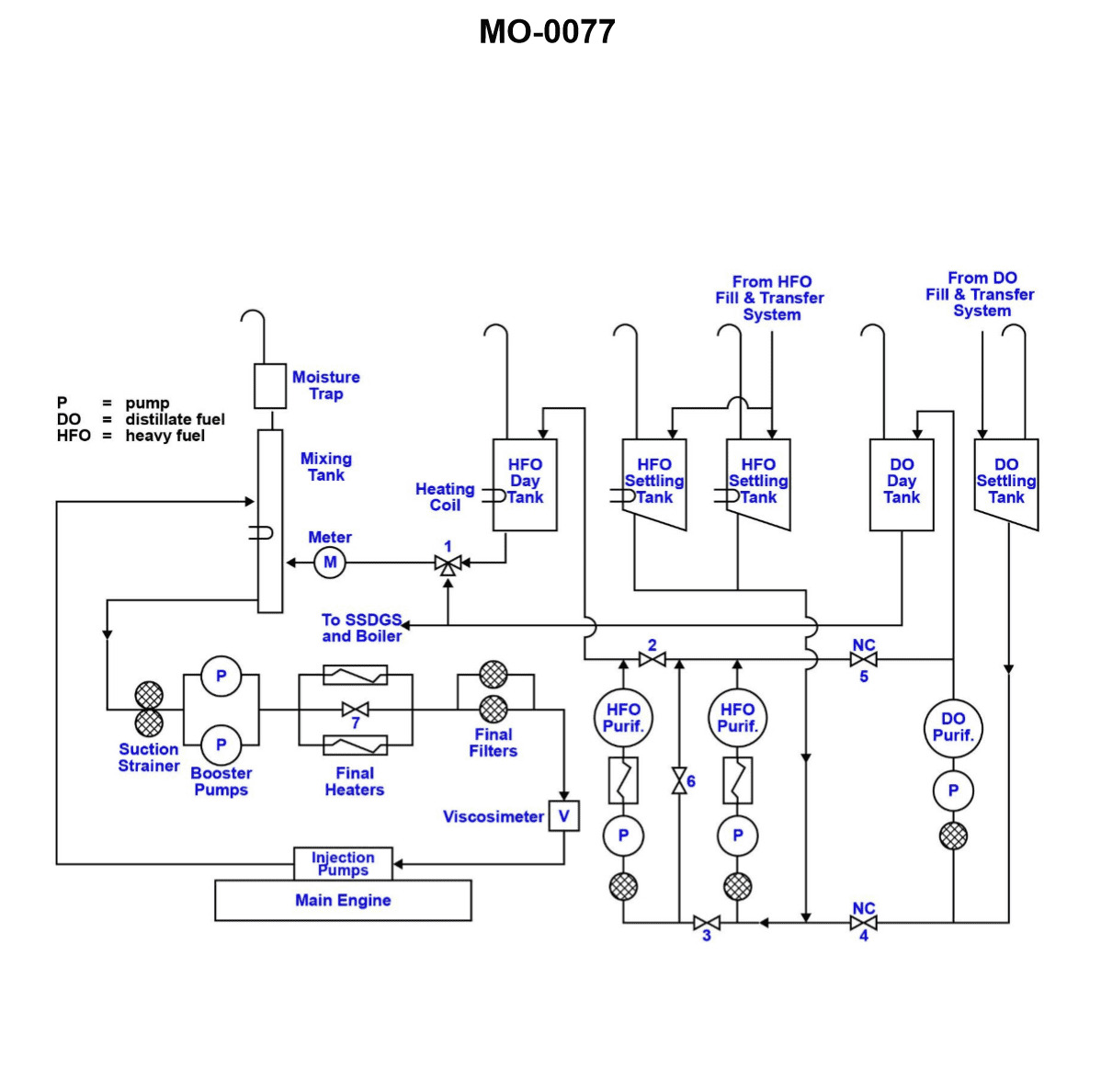
The Correct Answer is D ### Why Option D (Valves 2 and 3 CLOSED, and valve 6 OPEN) is Correct The goal is to operate the two heavy fuel oil (HFO) purifiers in **series**. This means the fuel must flow sequentially: from the dirty fuel tank/source, through the first purifier, then directly into the inlet of the second purifier, and finally out to the clean fuel tank/service system. 1. **Valves 2 and 3 CLOSED:** These valves typically control the direct flow path to the clean fuel tank *after* each individual purifier. * **Valve 2** controls the outlet flow from Purifier 1. If this valve is closed, the purified HFO from Purifier 1 is forced to flow downstream towards Purifier 2. * **Valve 3** is usually a bypass or a route that allows the discharge of Purifier 2 to go somewhere other than the common clean fuel outlet (depending on the exact piping layout), or it might simply allow Purifier 2 to discharge directly to the clean oil outlet if Purifier 1 is bypassed. For a series operation where Purifier 2 is the final stage, the flow path must be directed *through* Purifier 2. In most series schematics, closing valves 2 and 3 ensures that the flow from Purifier 1 is channeled to Purifier 2, and Purifier 2's discharge is directed solely to the clean fuel header. 2. **Valve 6 OPEN:** Valve 6 is usually located on the line connecting the clean oil discharge of Purifier 1 to the dirty oil inlet of Purifier 2. Opening this valve establishes the essential link needed for series operation, allowing the semi-purified HFO from the first machine to become the feed for the second machine. By closing the individual discharge valves (2 and 3, preventing parallel operation) and opening the connecting valve (6), the system ensures that the entire flow must pass through both purifiers sequentially. ### Why Other Options Are Incorrect **A) Valves 2, 3, and 6 all OPEN:** * **Incorrect Flow:** If Valves 2 and 3 are open, the fuel from Purifier 1 and the fuel from Purifier 2 would both discharge simultaneously into the clean fuel line. If Valve 6 is also open, some fuel might also bypass directly back to the inlet of Purifier 2, leading to uncontrolled flow and inefficient **parallel operation** (or a complex mixture of parallel and recirculation), not sequential series operation. **B) Valves 2, 3, and 6 all CLOSED:** * **No Flow:** If all three key valves are closed, the system is blocked. The fuel treated by Purifier 1 cannot reach Purifier 2 (Valve 6 closed) and cannot exit to the clean tank (Valves 2 and 3 closed). This configuration would halt fuel treatment. **C) Valves 2 and 3 OPEN, and valve 6 CLOSED:** * **Incorrect Flow:** If Valves 2 and 3 are open, the system is configured for **parallel operation**, where each purifier draws dirty fuel independently and discharges clean fuel simultaneously. Closing Valve 6 isolates the two purifiers from each other, guaranteeing they operate in parallel, which is the opposite of the required series configuration.
Pass Your Coast Guard Licensing Exams!
Study offline, track your progress, and simulate real exams with the Coast Guard Exams app