Question 59 MODE01 - Chief MODU Engineer
What is the normal bearing clearance permitted at the horizontal axis of the shaft for the bearing shown in the illustration? Illustration MO-0121
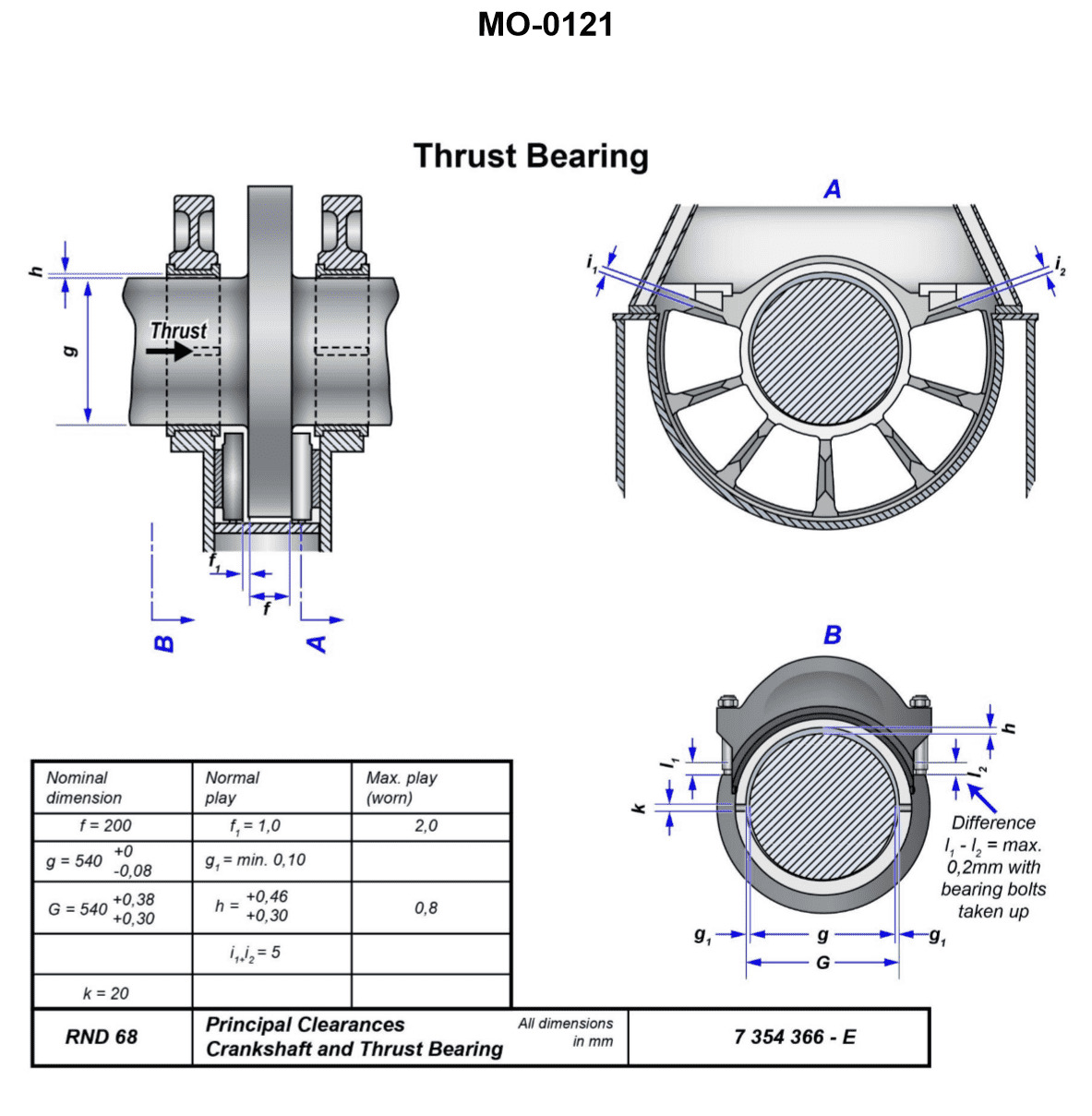
The Correct Answer is A **Explanation for Option A (Correct Answer):** Option A states that "The normal play on both sides of the shaft will be one tenth of a millimeter" (0.1 mm). This value (or range close to it, such as 0.08 mm to 0.12 mm) represents a standard, empirical tolerance used in marine engineering, particularly for large, slow-speed or medium-speed engine bearings (such as main bearings or large crosshead bearings, often depicted in standard engineering illustrations like MO-0121). A clearance of 0.1 mm measured across the diameter (total play/slack) is a common specification for ensuring proper oil film formation (hydrodynamic lubrication) without excessive vibration or impact damage. **Explanation for Option B (Incorrect):** Option B states that "The tolerances established are dependent on machining processes used and will vary amongst manufacturers." While manufacturing tolerances do exist and are crucial, the *bearing clearance* itself (the final running gap) is dictated by engineering specifications required for successful hydrodynamic lubrication and thermal expansion. This clearance is standardized within tight limits for a given engine type, regardless of which manufacturer made the parts, to ensure reliable operation. It is an operational requirement, not just a manufacturing tolerance variable. **Explanation for Option C (Incorrect):** Option C states that "The clearance on one side of the shaft at the axis will be one twentieth of a millimeter" (0.05 mm). If the clearance on one side (the radial clearance) is 0.05 mm, the total play on both sides (the diametral clearance) would be 0.1 mm. Therefore, while 0.05 mm is the radial clearance, the question asks for the "normal bearing clearance permitted at the horizontal axis," which is typically understood in practical measurement as the total *slack* or *play* (diametral clearance) measured using feeler gauges or lead wire (which measures the vertical axis). If Option A specifies the diametral clearance (0.1 mm) and Option C specifies the radial clearance (0.05 mm), Option A is the more standard way of expressing the measured play in engineering maintenance tests. Furthermore, in many contexts, "clearance" implies the total allowable slack, making Option A the most direct engineering answer. **Explanation for Option D (Incorrect):** Option D states that "The clearance is determined by the thickness of the hydrodynamic wedge formed and is not usually measured while underway." While the ultimate purpose of the clearance is to form a hydrodynamic wedge, the *permitted* (design) clearance is a fixed, measurable dimension used during assembly and maintenance (e.g., using lead wire or bridge gauges) to ensure the bearing will operate correctly. While the *dynamic* oil film thickness is not measured underway, the *static* required running clearance is an established tolerance (like 0.1 mm) that must be verified before operation.
Pass Your Coast Guard Licensing Exams!
Study offline, track your progress, and simulate real exams with the Coast Guard Exams app