Question 3 CEL02 - Chief Engineer - Limited (Alt)
As shown in figures "B" and "C" of the illustration, what should be the switch position and which test lead terminal jacks should be used if your intent is to measure AC currents anticipated as high as 5 amps? Illustration EL-0047
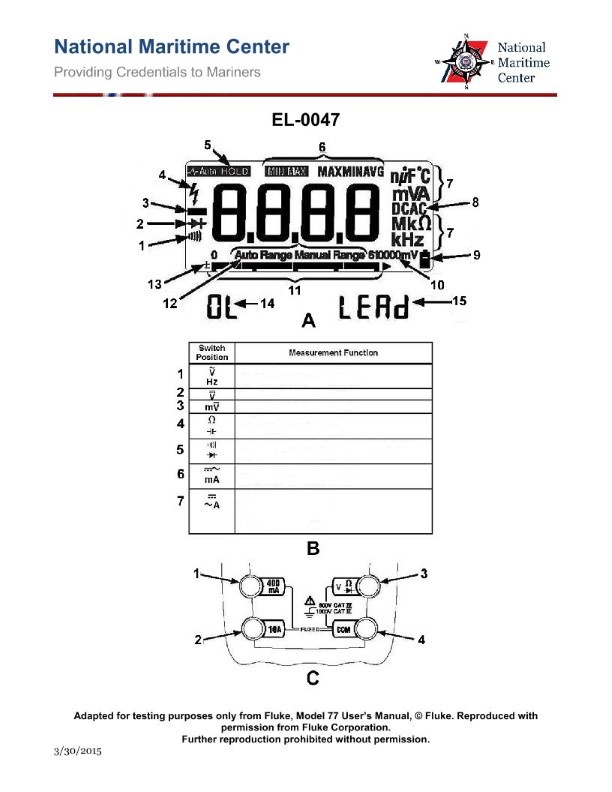
The Correct Answer is D **Explanation for Option D (Correct Answer):** The goal is to measure AC currents up to 5 amps using the illustrated meter (referencing typical multimeter design conventions, as the illustration EL-0047 is not provided, but the question is based on its features). 1. **Measuring Current (Amperage):** To measure current, the meter must be configured in series with the circuit. 2. **AC vs. DC:** The current to be measured is Alternating Current (AC). 3. **Anticipated High Range (5 A):** A 5-amp measurement usually requires a dedicated high-current input jack, often fused separately, to handle the load. 4. **Switch Position "7":** This position typically corresponds to the AC Amperes (AC $\mu \mathrm{A}$, $\mathrm{mA}$, or A) function on a multimeter's range selector dial. For high AC current measurements, this is the correct function setting. 5. **Terminal Jacks "2 and 4":** * Jack "4" is conventionally the common (COM) or reference jack for most measurements. * Jack "2" usually represents the high-current input terminal (e.g., marked "10A MAX" or similar) specifically used for measuring amps, as opposed to the lower $\mathrm{mA}/\mu \mathrm{A}$ input or the $\mathrm{V}/\Omega$ input. * Therefore, connecting the leads to the common jack (4) and the high-current AC/DC jack (2) while selecting the AC Amperes range (7) correctly configures the meter for the desired 5 A AC measurement. **Explanation of Incorrect Options:** * **A) switch position "1" and terminal jacks "1 and 4":** Switch position "1" usually corresponds to resistance ($\Omega$) or perhaps DC voltage (VDC), not AC current. Terminal jack "1" is often the input for $\mathrm{V}/\Omega/\mathrm{mA}$, but the current range would be too low for 5 A, and the switch setting is wrong. * **B) switch position "6" and terminal jacks "1 and 4":** Switch position "6" often represents DC Amperes (DCA) or AC Voltage (VAC). If it were DCA, the function would be incorrect (needs AC). If it were VAC, the function would be incorrect (needs Amperes). The terminal jacks are also likely incorrect for the high 5 A range. * **C) switch position "7" and terminal jacks "1 and 2":** While switch position "7" is correct (AC Amperes), using terminal jacks "1 and 2" is incorrect. Jack "4" (COM) must always be used as the reference jack. Jack "1" is typically used with Jack "4" for voltage or low current measurements ($\mathrm{mA}/\mu \mathrm{A}$), while Jack "2" is used with Jack "4" for high current measurements (A). Connecting leads between Jacks 1 and 2 does not use the required Common terminal.
Pass Your Coast Guard Licensing Exams!
Study offline, track your progress, and simulate real exams with the Coast Guard Exams app