Question 7 3AE01 - Third Assistant Engineer
The indicator card shown in the illustration is produced with a/an __________. Illustration MO-0108
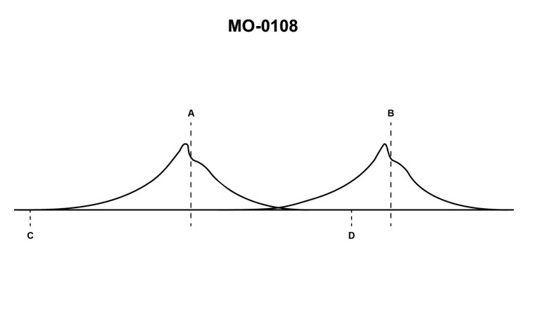
The Correct Answer is D **Explanation for Option D (rotating drum) being correct:** The term "indicator card" in mechanical engineering often refers to a pressure-volume (P-V) diagram or a pressure-time diagram generated for an engine cylinder (e.g., steam, diesel, or gasoline engines) or a compressor. Historically, these diagrams were traced mechanically onto paper (the indicator card). The standard device used to produce a modern indicator card that plots pressure (vertically) against crank angle or time (horizontally, representing the stroke) is the **engine indicator**. The mechanism responsible for converting the engine's piston movement or crank rotation into a proportional horizontal movement of the card paper (or tracing mechanism) is typically a **rotating drum** or barrel. The paper is wrapped around this rotating drum, and the drum spins synchronously with the engine's crank or stroke, allowing the tracing stylus to map pressure changes against position/time. **Explanation of why other options are incorrect:** * **A) balanced-diaphragm indicator:** A balanced-diaphragm is a component *within* some types of engine indicators or pressure transducers (measuring the pressure). It is the sensing element that detects pressure, but it is not the mechanism (drum) that moves the card paper horizontally to create the actual P-V or P-T *diagram* (the card itself). * **B) sliding camshaft:** A camshaft is a mechanism used to actuate valves (intake/exhaust) in a four-stroke engine. While it relates to engine timing, a *sliding* camshaft (or any camshaft) is not the mechanism used to drive the indicator paper or trace the diagram card. * **C) oscillating drum:** While early engine indicators (like the Crosby or steam engine indicators) often used a mechanism that pulled the paper back and forth during the stroke via a reducing motion (sometimes described as an oscillating or swinging mechanism), modern or common indicators designed to capture continuous cycles (especially P-T diagrams) use a mechanism where the drum rotates continuously, hence the term **rotating drum** is the standard mechanism associated with plotting the continuous trace onto the indicator card. The term 'oscillating drum' is less precise and less representative of the standard modern apparatus used to generate an engine indicator card tracing against crank angle.
Pass Your Coast Guard Licensing Exams!
Study offline, track your progress, and simulate real exams with the Coast Guard Exams app