Question 354Electricity & Electronics - QMED
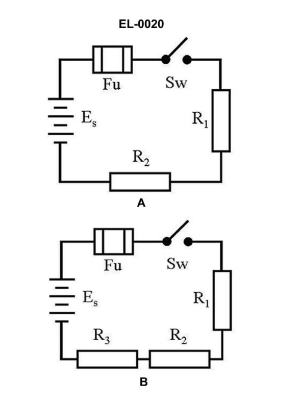
70% to passAs shown in figure "A" of the illustration if the applied voltage is 12 VDC, the resistance of R1 is 10 ohms, and R2 is 10 ohms what is the current flowing through R1 when the switch is closed? Illustration EL-0020
A0.6 amp
B0.833 amp
C1.2 amps
D2.4 amps
AI Explanation
The correct answer is A) 0.6 amp. According to Ohm's law, the current flowing through a resistor is equal to the applied voltage divided by the resistance of the resistor. In this case, the applied voltage is 12 VDC, and the resistance of R1 is 10 ohms. Plugging these values into the formula, we get: I = V/R = 12 V / 10 ohms = 1.2 amps. The other answer choices are incorrect because: B) 0.833 amp is incorrect as it does not match the calculation using Ohm's law. C) 1.2 amps is incorrect as it is the total current in the circuit, not the current flowing through R1. D) 2.4 amps is incorrect as it is double the correct answer, which does not match the given information.
Related Questions
Q246:In DC motor construction, where are the commutating windings wound? Q484:If a single-phase capacitor start induction motor fails to start, but instead hu... Q300:What damage may occur to the components of a winch master control switch, if the... Q264:Which of the following represents a characteristic of an ungrounded electrical d... Q506:When two generators are on the line and are both connected across a shared load,...
Ready to test your knowledge?
Take a Electricity & Electronics - QMED Practice ExamOfficial Resources