Question 238Electricity & Electronics - QMED
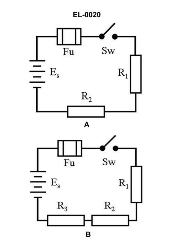
70% to passWhat is the total resistance of figure "B" of the illustrated circuit if the resistance of R1 is 3 ohms, R2 is 4 ohms, and R3 is 5 ohms? Illustration EL-0020
A0.5 ohms
B1.28 ohms
C1.5 ohms
D12 ohms
AI Explanation
The correct answer is D) 12 ohms. The total resistance of the circuit in figure "B" is the sum of the individual resistances R1, R2, and R3. Since R1 is 3 ohms, R2 is 4 ohms, and R3 is 5 ohms, the total resistance is the sum of these three values, which is 3 + 4 + 5 = 12 ohms. The other answer choices are incorrect because they do not accurately represent the total resistance of the circuit. Option A) 0.5 ohms is too low, option B) 1.28 ohms is too low, and option C) 1.5 ohms is too low. The correct answer, as per the information provided in the illustration and question, is 12 ohms.
Related Questions
Q290:What is an ammeter used to measure? Q137:What can be the cause of excessive heat or burning contacts in an operating moto... Q356:A battery is connected to a circuit containing three resistors in parallel. The ... Q177:Diesel-generators number 1 and number 2 are operating in parallel at near full l... Q442:When troubleshooting a motor controller, all indications are that a relay coil s...
Ready to test your knowledge?
Take a Electricity & Electronics - QMED Practice ExamOfficial Resources