Question 198Electricity & Electronics - QMED
70% to passIf it is required that the coils 'R1-R2-R3' in the indicator of figure "A", turn opposite to those in the transmitter, as shown in the illustration, what action should be taken? Illustration EL-0092
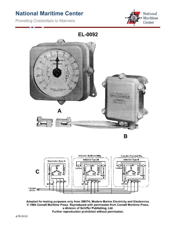
AInterchange leads 'R1' and 'R3'.
BInterchange leads 'R2' and 'R3'.
CReverse the 60 Hz supply connections to 'S1' and 'S2'.
DNo action is needed.
AI Explanation
The correct answer is A) Interchange leads 'R1' and 'R3'. The reasoning is that for the indicator in figure "A" to turn in the opposite direction of the transmitter, the coils 'R1-R2-R3' in the indicator need to be connected in the reverse order compared to the transmitter. Interchanging the leads 'R1' and 'R3' will achieve this, as it will reverse the direction of the coils in the indicator. The other options are incorrect because B) interchanging 'R2' and 'R3' would not reverse the direction, C) reversing the 60 Hz supply connections would not address the issue with the coil order, and D) some action is needed to correct the coil orientation.
Related Questions
Q248:The counter EMF of a DC motor is maximum when the _______________. Q272:Brushes in a DC generator must be positioned in the neutral plane to avoid exces... Q380:Which statement is true concerning a split-phase induction motor? Q291:In order to take a current reading with a 'clamp-on' ammeter, what should be the... Q376:Where is the power necessary to energize the howler "relay" coil at the engine r...
Ready to test your knowledge?
Take a Electricity & Electronics - QMED Practice ExamOfficial Resources