Question 19Electricity & Electronics - 1st Asst/Chief
70% to passWhich of the illustrated resistors represents the schematic symbol shown in figure "B"? Illustration EL-0021
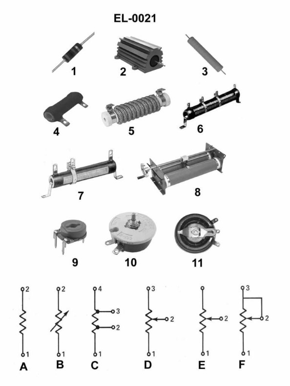
Afigure "4"
Bfigure "6"
Cfigure "10"
Dfigure "11"
AI Explanation
The correct answer is C) figure "10". The schematic symbol shown in figure "B" represents a fixed or non-adjustable resistor. This is consistent with the resistor illustrated in figure "10", which depicts a fixed, non-adjustable resistor. The other answer choices do not match the schematic symbol shown in figure "B". Figure "4" represents a potentiometer or variable resistor, figure "6" depicts a thermistor, and figure "11" shows a resistor network or array, none of which match the fixed resistor symbol in figure "B".
Related Questions
Q271:What is the function of the autotransformers used with autotransformer starters ...
Q73:What would be the indication of a burned-out LED?
Q118:On DC diesel-electric drives, how is the speed of the DC propulsion motor primar...
Q75:Which of the following conditions would most likely lead to the failure of a res...
Q274:What is the device shown in figure "B" of the illustration between the source ci...
Ready to test your knowledge?
Take a Electricity & Electronics - 1st Asst/Chief Practice ExamOfficial Resources
Pass Your Coast Guard Licensing Exams!
Study offline, track your progress, and simulate real exams with the Coast Guard Exams app