Question 123Electricity & Electronics - 1st Asst/Chief
70% to passAs shown in figure "A" of the illustration, with a digital multimeter set up as an ohmmeter, what set of readings would be consistent with an open in phase "C" of the single circuit, wye-connected stator windings as shown? Illustration EL-0201
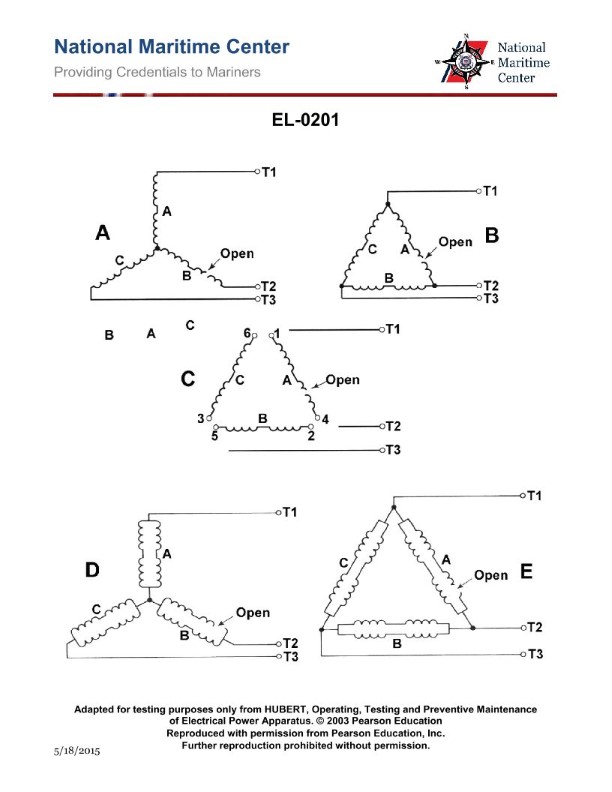
The correct answer is C) T1 to T2: "OL ohms"; T2 to T3: "OL ohms"; T3 to T1: "1.8 ohms". This is correct because an open in phase "C" of the single circuit, wye-connected stator windings would result in an open circuit (infinite resistance or "OL ohms") between T1 to T2 and T2 to T3, while the resistance between T3 to T1 would still be 1.8 ohms, as this represents the healthy phases. The other options are incorrect because they do not accurately reflect the readings that would be observed with an open in phase "C". Options A, B, and D either have incorrect resistance values or do not have the open circuit readings in the appropriate locations.
Ready to test your knowledge?
Take a Electricity & Electronics - 1st Asst/Chief Practice ExamPass Your Coast Guard Licensing Exams!
Study offline, track your progress, and simulate real exams with the Coast Guard Exams app