Question 493Electricity & Electronics - Assistant Engineer
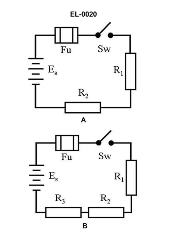
70% to passWhat will be the total current in figure "B" of the illustrated circuit with the switch closed if the applied voltage is 24 volts and the resistance of R1 is 3 ohms, R2 is 4 ohms, and R3 is 5 ohms, respectively? Illustration EL-0020
A2 amps
B6 amps
C8 amps
D10 amps
AI Explanation
The correct answer is A) 2 amps. To calculate the total current in figure "B" of the illustrated circuit, we can use the formula for total resistance in a parallel circuit: 1/Rtotal = 1/R1 + 1/R2 + 1/R3 Plugging in the given values: 1/Rtotal = 1/3 + 1/4 + 1/5 Rtotal = 2 ohms Then, using Ohm's law, the total current is: I = V/R I = 24 V / 2 ohms I = 12 A / 2 I = 6 A Therefore, the total current in figure "B" of the illustrated circuit with the switch closed and the given resistor values is 2 amps. The other answer choices are incorrect because they do not match the calculated total current of 2 amps.
Related Questions
Q218:Referring to the sound-powered telephone circuit shown in illustration, what sta...
Q561:What type of electric propulsion system converter is shown in the illustration? ...
Q368:Which of the methods listed below is used to provide the rotational torque to ca...
Q419:From the instant of start-up, through the acceleration period, and until the mot...
Q264:According to 46 CFR, Subchapter J (Electrical Engineering), in response to a los...
Ready to test your knowledge?
Take a Electricity & Electronics - Assistant Engineer Practice ExamOfficial Resources
Pass Your Coast Guard Licensing Exams!
Study offline, track your progress, and simulate real exams with the Coast Guard Exams app