Question 491Electricity & Electronics - Assistant Engineer
70% to passIn figure "A" of the illustration, 12 volts is applied to the circuit where the resistance of R1 is 10 ohms and R2 is 10 ohms. What is the voltage across R2 when the switch is closed? Illustration EL-0020
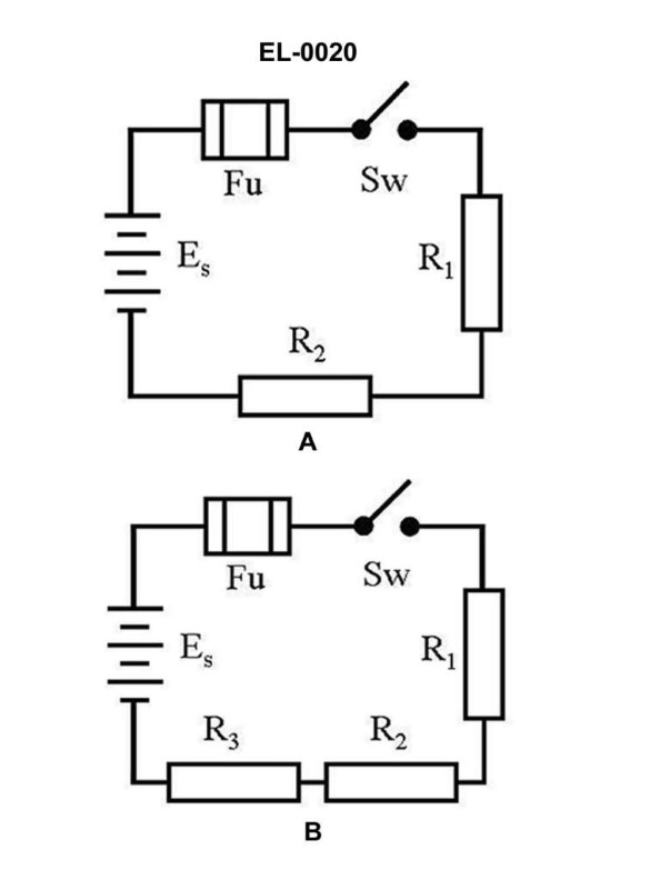
The correct answer is C) 6 volts. When the switch is closed in the circuit shown in Figure A, the voltage across R2 will be 6 volts. This is because R1 and R2 are connected in series, and the total resistance of the circuit is 20 ohms (10 ohms for R1 and 10 ohms for R2). According to Ohm's law, the voltage across each resistor is proportional to its resistance, so the voltage across R2 will be half of the total voltage, which is 12 volts. The other options are incorrect because: A) 1.2 volts is too low and does not align with Ohm's law. B) 2 volts is too low and does not align with Ohm's law. D) 12 volts is the total voltage applied to the circuit, not the voltage across R2.
Ready to test your knowledge?
Take a Electricity & Electronics - Assistant Engineer Practice ExamPass Your Coast Guard Licensing Exams!
Study offline, track your progress, and simulate real exams with the Coast Guard Exams app