Question 376Electricity & Electronics - Assistant Engineer
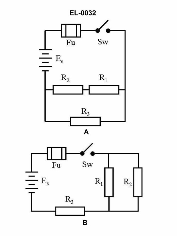
70% to passWhat would be the total current draw of the circuit as shown in figure "A" of the illustration if the source voltage is 24 volts, the resistance for R1 is 12 ohms, the resistance for R2 is 24 ohms, and the resistance for R3 is 36 ohms? Illustration EL-0032
A0.33 amperes
B0.75 amperes
C1.25 amperes
D1.33 amperes
AI Explanation
The correct answer is D) 1.33 amperes. To calculate the total current draw of the circuit, we can use Ohm's law, which states that the current (I) is equal to the voltage (V) divided by the resistance (R). In this case, the source voltage is 24 volts, and the resistances are R1 = 12 ohms, R2 = 24 ohms, and R3 = 36 ohms. Applying Ohm's law, the total current draw is 24 volts / (12 ohms + 24 ohms + 36 ohms) = 24 volts / 72 ohms = 1.33 amperes. The other options are incorrect because they do not accurately represent the total current draw based on the given information.
Related Questions
Q408:Refer to figure "A" representing an electric oven as shown in the illustration. ...
Q441:In the illustration, 1, 2, 3 and 4 are 12 volt batteries. What will be the nomin...
Q470:The component labeled 'CR1' in the circuit shown in the illustration serves what...
Q432:In actual applications, electrical connections associated with 'R1, R2 and R3' o...
Q271:Which of the listed pairs of materials make the best insulators?
Ready to test your knowledge?
Take a Electricity & Electronics - Assistant Engineer Practice ExamOfficial Resources
Pass Your Coast Guard Licensing Exams!
Study offline, track your progress, and simulate real exams with the Coast Guard Exams app