Question 350Electricity & Electronics - Assistant Engineer
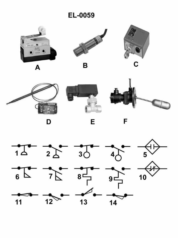
70% to passWhich of the electrical schematic symbols shown in the illustration represents a normally closed limit switch? Illustration EL-0059
A6
B10
C11
D14
AI Explanation
The correct answer is C) 11. The electrical schematic symbol represented by option C) 11 is the symbol for a normally closed limit switch. A normally closed limit switch is an electrical switch that is closed (conducting) when the switch is not actuated, and opens (non-conducting) when the switch is activated, such as by contact with an object. The other options do not represent a normally closed limit switch. Option A) 6 is the symbol for a resistor, option B) 10 is the symbol for a normally open limit switch, and option D) 14 is the symbol for a push-button switch.
Related Questions
Q164:Regarding an induction motor, what does the power developed by the rotor automat...
Q21:If the primary winding of a voltage transformer is connected to a steady DC sour...
Q2:What is the characteristic of a wound-rotor induction motor, with a high resista...
Q378:Referring to the illustration pertaining to a steering system hydraulic power un...
Q452:In a series circuit what is the total applied voltage equal to?
Ready to test your knowledge?
Take a Electricity & Electronics - Assistant Engineer Practice ExamOfficial Resources
Pass Your Coast Guard Licensing Exams!
Study offline, track your progress, and simulate real exams with the Coast Guard Exams app