Question 113Electricity & Electronics - Assistant Engineer
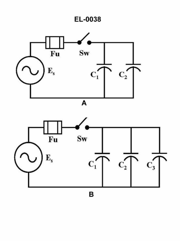
70% to passWhat would be the capacitive reactance of the circuit shown in figure "A" of the illustration if the capacitance of C1 was 100 microfarads, the capacitance of C2 was 200 microfarads and the frequency of the source was 60 cycles per second (Hz)? Illustration EL-0038
A8.8 ohms
B17.7 ohms
C39.8 ohms
D79.6 ohms
AI Explanation
The correct answer is A) 8.8 ohms. The capacitive reactance (Xc) of a circuit is calculated using the formula Xc = 1 / (2πfC), where f is the frequency of the source and C is the capacitance. In this case, the frequency is 60 Hz, and the capacitances are 100 microfarads (0.0001 farads) for C1 and 200 microfarads (0.0002 farads) for C2. Plugging these values into the formula, we get Xc1 = 1 / (2π * 60 * 0.0001) = 26.5 ohms for C1, and Xc2 = 1 / (2π * 60 * 0.0002) = 13.3 ohms for C2. The total capacitive reactance of the circuit is the parallel combination of these two reactances, which is 8.8 ohms.
Related Questions
Q149:The multiplier prefix 'giga' (G) such as used in "gigabytes" represents what mul...
Q264:According to 46 CFR, Subchapter J (Electrical Engineering), in response to a los...
Q357:Referring to figure "3" of the illustration, what type of logic gate is symboliz...
Q402:As shown in the illustration of an electrically operated watertight door control...
Q159:When a megohmmeter is being used to test insulation resistance, current leakage ...
Ready to test your knowledge?
Take a Electricity & Electronics - Assistant Engineer Practice ExamOfficial Resources
Pass Your Coast Guard Licensing Exams!
Study offline, track your progress, and simulate real exams with the Coast Guard Exams app