Question 48 QMED04 - Boiler Technician-Watertender
Item 4 shown in the illustration represents a __________. Illustration GS-0125
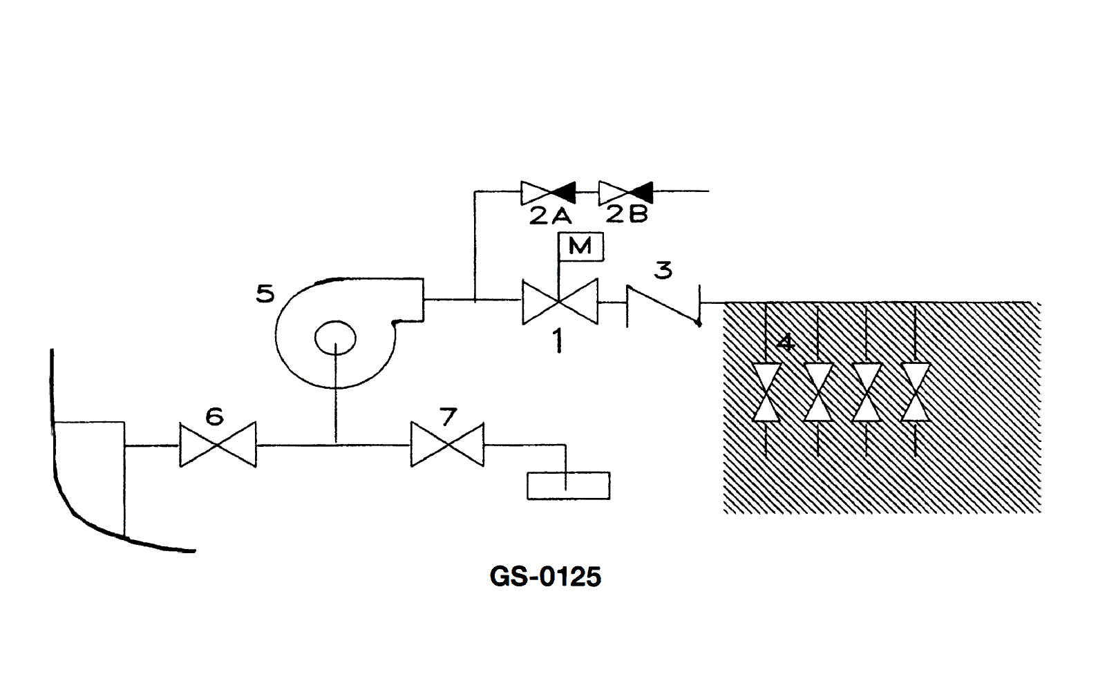
The Correct Answer is A **Explanation for A (manifold):** In marine engineering or process systems (which illustrations like GS-0125 often depict, focusing on piping schematics), a manifold is a pipe or chamber having several outlets or inlets that serves to divide or combine fluid flow. Item 4, based on standard illustrations of fluid handling systems, typically represents a section where multiple lines converge into a common header (inlet manifold) or diverge from a common header (distribution manifold). This component is designed to manage the flow control and routing for several separate pipelines, which is the defining function of a manifold. **Explanation for Incorrect Options:** * **B) suction line:** A suction line is a single pipe that draws fluid into a pump or system. While lines connected to the manifold may be suction lines, the manifold (Item 4) itself is the distributing/collecting device, not just a single flow line. * **C) bilge system:** A bilge system is the overall network of piping, pumps, and valves designed to remove water from the lower compartments (bilges) of a vessel. Item 4 is a specific component *within* a larger fluid system (which could be the bilge system), but it is not the entire system itself. * **D) vacuum branch line:** A vacuum branch line is a specific type of piping used to draw a vacuum. Like a suction line, this describes a single pipe's function. The manifold (Item 4) is the central fitting that connects multiple such lines, rather than being a single branch line.
Pass Your Coast Guard Licensing Exams!
Study offline, track your progress, and simulate real exams with the Coast Guard Exams app