Question 63 QMED02 - Electrician-Refrigerating Engineer
The illustrated drawing shows a correct front "F" and top "T" view of an object. Of the views labeled "1","2","3", and "4", the one that correctly represents the right side view for a third angle projection is_______. Illustration GS-0132
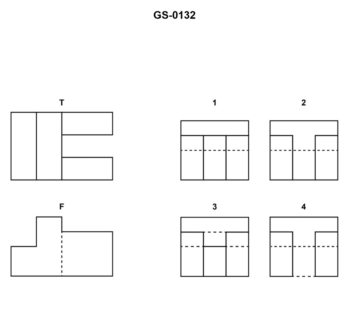
The Correct Answer is B ### Explanation for why Option B ("2") is Correct: The problem asks for the correct right side view using a **third angle projection**. In third angle projection, the view is placed in the quadrant adjacent to the face it represents: the top view is placed above the front view, and the right side view is placed to the right of the front view. The front view (F) shows the object has a main rectangular base and an upper, narrower rectangular block centered on the base. To generate the right side view (R), we look at the object from the right side. 1. **Overall Shape:** The object, when viewed from the right, will appear as a rectangle. 2. **Hidden/Visible Features:** The front view (F) and top view (T) both confirm that the upper block is narrower than the base block. Therefore, when looking from the right, the sides of the **upper block** (which are parallel to the viewing direction) are visible. The sides of the **base block** (which extend beyond the upper block) are also visible. Crucially, the **recessed corners** (where the upper block meets the base) are visible edges. 3. **Projection:** The height of the base and the height of the step up to the upper block must align horizontally with the front view (F). The width of the base must align horizontally with the top view (T) and transfer to the right side view (R). View **2** correctly depicts this structure: it shows a large rectangle representing the overall width and height, and an internal horizontal line. This internal horizontal line represents the shoulder or step formed by the narrower upper block resting on the wider base block. Since this step/shoulder is a visible edge when looking from the right (the base is wider than the top block), it is drawn as a **solid line**. ### Explanation for why the other options are incorrect: * **A) 1 is incorrect:** View 1 shows a simple solid rectangle with no internal lines. This would represent a simple rectangular prism, not the stepped object shown in the front and top views. * **C) 3 is incorrect:** View 3 shows a solid rectangle with an internal horizontal **dashed (hidden)** line. A dashed line indicates an edge that is not visible from the viewing direction. The step/shoulder in this object is clearly visible when looking from the right side (because the base block is wider than the upper block), so it must be represented by a solid line. * **D) 4 is incorrect:** View 4 shows a solid rectangle with an internal vertical dashed line. This configuration would represent a hole or slot running through the object from front to back, which is not indicated in the provided top (T) or front (F) views. Furthermore, the object's structure requires a horizontal internal line to depict the height step, not a vertical line.
Pass Your Coast Guard Licensing Exams!
Study offline, track your progress, and simulate real exams with the Coast Guard Exams app