Question 39 CEL02 - Chief Engineer - Limited (Alt)
In order to definitively determine whether or not fuse "1", shown in the illustration is blown using an on-line testing technique, across what points would you connect the voltmeter leads? Illustration EL-0062
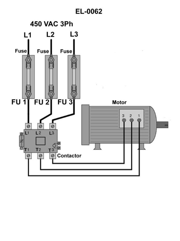
The Correct Answer is C ### 2. Explanation of why Option C is correct: The procedure described in Option C is the standard technique for definitively testing a fuse (or conductor) for continuity in an energized (on-line) circuit using a known good circuit as a reference. * **Connection Setup:** Option C requires connecting the voltmeter leads between: * Point 1: The bottom (load side) of fuse "1". * Point 2: The top (source side) of either fuse "2" or fuse "3" (the reference circuit). * **Analysis of Results:** * **If Fuse "1" is GOOD:** Both the top (source) and the bottom (load) of Fuses 1, 2, and 3 are connected to the main supply line (assuming a common bus bar). The bottom of F1 and the top of F2/F3 will be at essentially the same potential. The voltmeter will read **0 Volts** (or near 0 V). * **If Fuse "1" is BLOWN:** Fuse "1" is now an open circuit. The bottom (load side) of F1 is disconnected from the source and its voltage is determined by the downstream load (often floating near 0V relative to the source terminal). The top (source side) of F2/F3 is still connected to the full supply voltage. The voltmeter is now measuring the potential difference between the full source voltage and the load-side potential, resulting in a reading equal to the **full line/supply voltage**. This full-voltage reading definitively indicates that fuse "1" is blown. ### 3. Explanation of why other options are incorrect: * **A) from the top of fuse "1" and the bottom of either fuse "2" or fuse "3"** * If the circuit is operational, both the top of F1 (source) and the bottom of F2/F3 (load side of a good fuse) are at the same potential (supply voltage). The reading will always be 0V, regardless of whether F1 is blown, because the power supply to the load of F2/F3 is maintained. This fails to detect the fault in F1. * **B) from the top of fuse "1" and the top of either fuse "2" or fuse "3"** * Since all three fuses typically share the same source bus bar, the top of F1 and the top of F2/F3 will always be at the identical source potential. The voltage difference will be 0 V whether F1 is good or blown. This test is useless for determining the status of F1. * **D) from the bottom of fuse "1" and the bottom of either fuse "2" or fuse "3"** * If F1 is good, both points are at the load potential, reading 0V. * If F1 is blown, the load side of F1 may float to a different potential than the load side of the good fuse (F2/F3). While a voltage *might* be registered, this measurement relies on the characteristics of the downstream load and does not directly utilize the reference source voltage, making it less reliable and less definitive than the Source-to-Disconnected-Load measurement provided by Option C.
Pass Your Coast Guard Licensing Exams!
Study offline, track your progress, and simulate real exams with the Coast Guard Exams app