Question 55 AEL01 - Assistant Engineer - Limited
The main engines on your vessel are fitted with speed control governors based on the operating principle shown in the illustration. What statement is true concerning the illustrated pressure-compensated governor? Illustration MO-0159
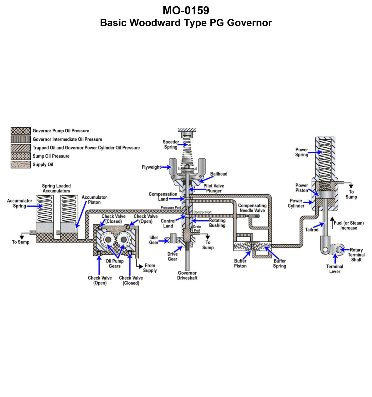
The Correct Answer is C **Explanation for C:** In a typical mechanical-hydraulic speed control governor (like the pressure-compensated type illustrated), the core function is to maintain a set speed. This is achieved through the interaction of two opposing forces acting on the flyweights: 1. **Speeder Spring Force (Set Point):** This force, set by the speed adjusting mechanism, tries to push the flyweights inward. 2. **Centrifugal Force (Actual Speed):** This force, generated by the rotation of the flyweights, tries to push the flyweights outward. When the engine is running at the desired set speed (the **on-speed** condition), these two forces are in equilibrium. * When the forces are balanced, the flyweights assume a specific operational angle, often designed to be near vertical or in a neutral position (sometimes called the "level" or "on-speed" position). * This neutral flyweight position mechanically centers the **pilot valve plunger**. * When the pilot valve plunger is centered, its land precisely covers the control port (or ports) leading to the power piston (servomotor). This action blocks oil flow, preventing the servomotor from moving the fuel rack. Therefore, "With the speeder spring compression force and the flyweight centrifugal force in equilibrium, the flyweights are pivoted to vertical and the pilot valve plunger will be in the centered position blocking off the control port" is the accurate description of the on-speed (stable) state. **Why the other options are incorrect:** * **A) Incorrect:** If the flyweight centrifugal force and spring force are in equilibrium (on-speed), the system should be stable (pilot valve centered). If the flyweights pivoted fully outward (and the pilot valve plunger was lowered, draining oil), this would signal an **overspeed** condition, causing the governor to reduce fuel, which contradicts the condition of equilibrium. * **B) Incorrect:** If the flyweights pivoted inward (and the pilot valve plunger was raised, supplying pressure), this would signal an **underspeed** condition, causing the governor to increase fuel, which contradicts the condition of equilibrium. The equilibrium state requires the flyweights to be in the neutral position, keeping the pilot valve centered. * **D) Incorrect:** In a mechanical-hydraulic governor, the position of the flyweights directly dictates the position of the pilot valve plunger. When the two opposing forces are in equilibrium, the flyweights must be in the precise neutral (on-speed) position, which uniquely defines the pilot valve plunger's position as centered. It cannot be in "any position."
Pass Your Coast Guard Licensing Exams!
Study offline, track your progress, and simulate real exams with the Coast Guard Exams app