Question 47 1AE01 - First Assistant Engineer
The components indicated as "7" and "8" as shown in the illustration, are known as the __________. Illustration GS-0153
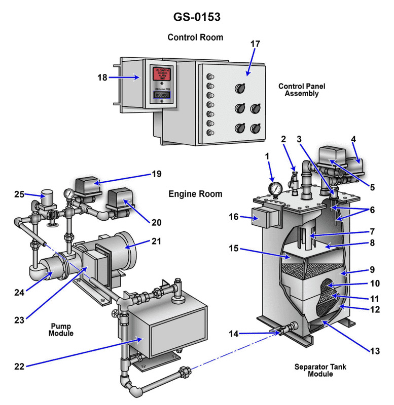
The Correct Answer is A. **Explanation for A (inlet weir and inlet baffle):** Option A is correct because, based on standard industrial illustrations (such as GS-0153, which typically depicts gravity separators or API oil/water separators), components placed directly at the point where fluid enters the vessel are designed to manage flow and distribution. Component "7" is typically an **inlet weir** (or distribution baffle/box) that helps distribute the incoming flow evenly across the cross-section of the separator. Component "8" is typically the **inlet baffle** (or diffuser) immediately downstream of the inlet, whose primary function is to break the velocity of the incoming stream, reduce turbulence, and allow the separation process (oil rising) to begin efficiently without disturbing the existing contents. These two components work together at the inlet section. **Explanation for why other options are incorrect:** * **B) second stage oil separator and drip pan:** This is incorrect. Components 7 and 8 are located at the inlet of the unit. Furthermore, "second stage oil separator" refers to an entirely separate piece of equipment or a section far downstream, and "drip pan" is generally not a primary hydraulic component in this context. * **C) first stage oil separator and drip pan:** This is incorrect for similar reasons as B. While the vessel itself might be considered the "first stage" of separation, components 7 and 8 are specific internal flow control devices, not the definition of the entire separation stage, and "drip pan" is hydraulically inaccurate. * **D) outlet weir and outlet baffle:** This is incorrect because components 7 and 8 are located at the **inlet** of the vessel (where the fluid enters). The outlet weir and outlet baffle are located at the opposite end, governing the exit of the treated water phase and maintaining the liquid level.
Pass Your Coast Guard Licensing Exams!
Study offline, track your progress, and simulate real exams with the Coast Guard Exams app