Question 31 1AE01 - First Assistant Engineer
A hydraulic system flow control circuit is shown in the illustration and is known as a __________. Illustration GS-0105
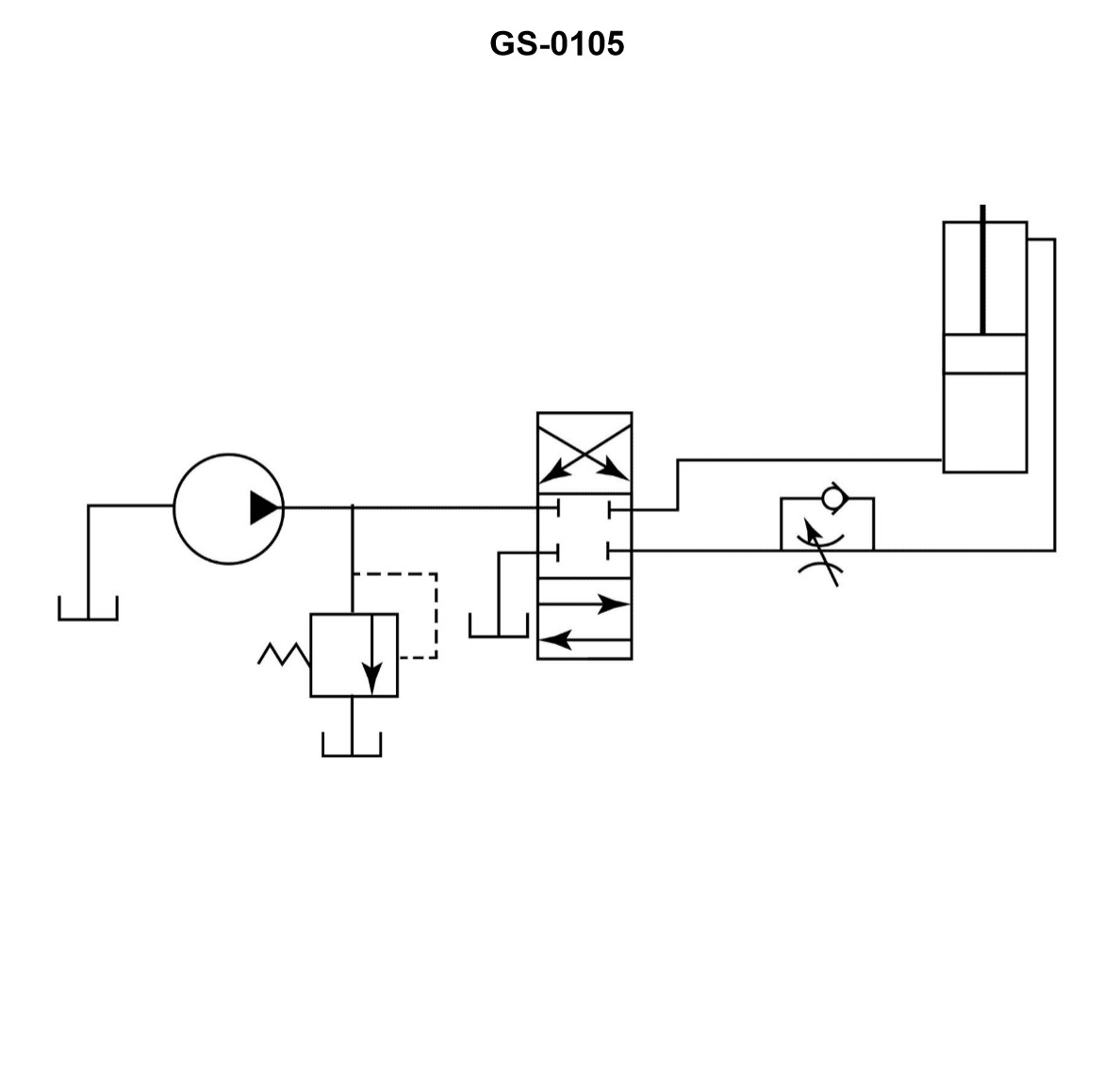
The Correct Answer is A ### Explanation for Option A (Metered-in circuit) A **metered-in circuit** controls the flow rate of fluid *entering* the actuator (like a hydraulic cylinder or motor). This control is achieved by placing a flow control valve (often a restriction or throttle) directly in the pressure line leading to the inlet port of the actuator. By throttling the supply flow before it enters the cylinder, the speed of the actuator is directly regulated during the extension stroke. The illustration GS-0105 depicts exactly this arrangement: a flow control valve regulating the flow *into* the cylinder on the driving side. ### Explanation for Incorrect Options **B) bleed-in circuit:** This term is not standard terminology used to describe fundamental hydraulic speed control methods. Speed control circuits are typically categorized as metered-in, metered-out, or bleed-off. **C) metered-out circuit:** A metered-out circuit controls the speed of the actuator by regulating the flow of fluid *leaving* the cylinder (the exhaust or return flow). The flow control valve would be placed in the return line. This setup is primarily used to control loads that might run away (e.g., vertical downward loads) because it ensures the cylinder is always pressurized against a resistance. The illustrated circuit controls the inlet flow, not the outlet flow. **D) bleed-off circuit:** A bleed-off (or bypass) circuit controls the speed by diverting (bleeding) a portion of the pump's flow directly back to the reservoir, *before* it reaches the actuator. The flow control valve is placed in a parallel line between the pressure line and the reservoir, bypassing the actuator. This reduces the effective flow rate available to move the load. The illustrated circuit shows the flow control valve directly in series with the actuator, regulating the input flow, not diverting it.
Pass Your Coast Guard Licensing Exams!
Study offline, track your progress, and simulate real exams with the Coast Guard Exams app