Pass Your Coast Guard Licensing Exams!
Study offline, track your progress, and simulate real exams with the Coast Guard Exams app
UFIV01 - Chief Engineer - UFIV
49 images
Question 1
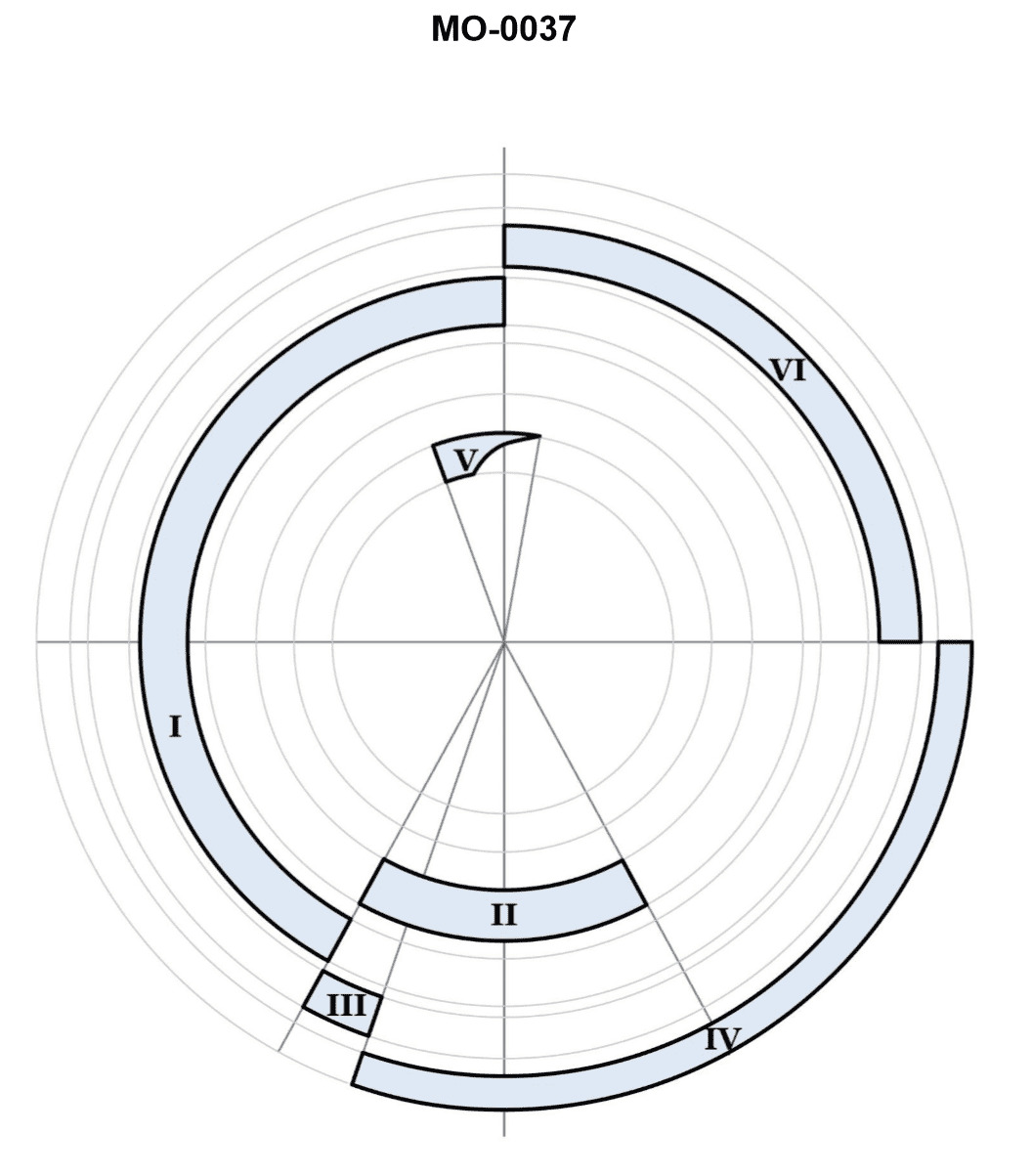
Question: You are assigned to an uninspected fishing industry line vessel fitted with main propulsion diesel engines operating on the cycle represented in the polar timing diagram shown in the illustration. What events or effects are represented by "II", "III", and "IV" respectively? Illustration MO-0037
A. "II" represents the exhaust period where the exhaust valves are held open. "III" represents a pressure loss effect where the cylinder pressure is lowered by exhaust blowdown. "IV" represents the scavenging period where the scavenging-air ports are uncovered.
B. "II" represents the exhaust period where the exhaust valves are held open. "III" represents a supercharging effect where the cylinder pressure is boosted with the scavenging air blower. "IV" represents the scavenging period where the scavenging-air ports are uncovered.
C. "II" represents the scavenging period where the scavenging-air ports are uncovered. "III" represents a pressure loss effect where the cylinder pressure is lowered by exhaust blowdown. "IV" represents the exhaust period where the exhaust valves are held open.
D. "II" represents the scavenging period where the scavenging-air ports are uncovered. "III" represents a supercharging effect where the cylinder pressure is boosted with the scavenging air blower. "IV" represents the exhaust period where the exhaust valves are held open.
The Correct Answer is D 1. **Explanation for Option D being Correct:** * **Context:** The illustration MO-0037 depicts a polar timing diagram (or valve/port timing diagram) for a large, slow-speed, uninspected fishing industry line vessel operating with main propulsion diesel engines. These diagrams typically represent two-stroke cycle engines, which utilize scavenging and have timed port/valve openings relative to the crankshaft angle (TDC/BDC). * **"II" represents the scavenging period where the scavenging-air ports are uncovered:** In a two-stroke engine, scavenging air is introduced to push residual exhaust gases out. On the timing diagram, the scavenging ports typically open slightly before the exhaust closes, allowing pressurized air to enter the cylinder. "II" represents the initial period of flow controlled by the uncovering of the ports. * **"III" represents a supercharging effect where the cylinder pressure is boosted with the scavenging air blower:** After the scavenging process is complete (residual gases removed), the pressure of the inlet air (supplied by the blower/turbocharger) often remains higher than the atmospheric pressure or the pressure required for simple scavenging. This final boost, achieved by delaying the closure of the inlet ports/valves, is known as a supercharging effect (sometimes called 'packing'), which increases the density and amount of air trapped for combustion. "III" usually represents this overlap/boosting phase just before compression begins. * **"IV" represents the exhaust period where the exhaust valves are held open:** The exhaust process must begin before BDC (Blowdown) and continue through BDC while the piston moves upward. "IV" represents the main duration where the exhaust gases are expelled from the cylinder, controlled by the opening of the exhaust valve(s) (in uniflow scavenged engines) or the exhaust ports. 2. **Why other options are incorrect:** * **Option A is incorrect:** * It incorrectly identifies "II" as the exhaust period and "IV" as the scavenging period. The scavenging period typically precedes the compression stroke immediately and the exhaust period is much longer, starting well before BDC. Furthermore, while "III" describes a pressure loss (exhaust blowdown), the diagram typically uses "III" to indicate the boosting/supercharging effect achieved by the scavenging system after the main exhaust period is completed and the ports are still open. * **Option B is incorrect:** * It incorrectly identifies "II" as the exhaust period. "II" is situated where the scavenging ports are uncovered just before the compression stroke officially starts. While it correctly identifies "III" as supercharging and "IV" as scavenging, the labeling of "II" and "IV" is reversed compared to the standard representation of the scavenging and exhaust events on the diagram. * **Option C is incorrect:** * It incorrectly identifies "II" as the scavenging period and "IV" as the exhaust period (consistent with D), but it incorrectly identifies "III" as a pressure loss effect due to exhaust blowdown. "III" occurs *after* the blowdown (which happens much earlier, when the exhaust valve first opens) and is specifically the period where the inlet pressure is maintained or boosted to maximize the trapped air charge (supercharging).
Question 2
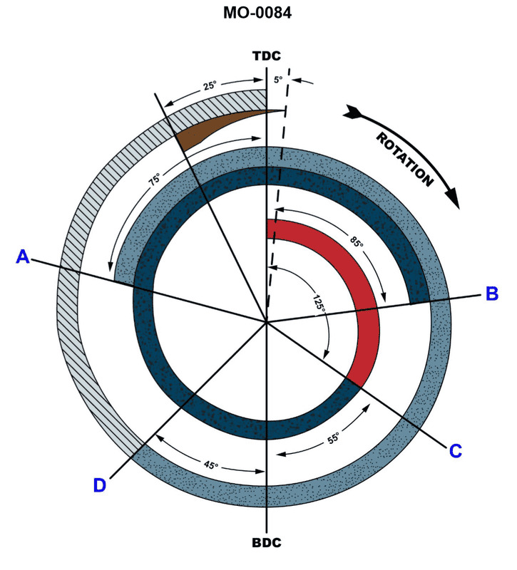
Question: You are assigned to a fishery research vessel fitted with main propulsion diesel engines operating on the cycle represented in the polar timing diagram shown in the illustration. When do the intake valves open and close respectively? Illustration MO-0084
A. The intake valves open at 45o after bottom dead center on the compression stroke. The intake valves close at 75o before top dead center on the exhaust.
B. The intake valves open at top dead center at the beginning of the intake stroke. The intake valves close at bottom dead center at the end of the intake stroke.
C. The intake valves open at bottom dead center at the end of the intake stroke. The intake valves close at top dead center at the beginning of the intake stroke.
D. The intake valves open at 75o before top dead center on the exhaust stroke. The intake valves close at 45o after bottom dead center on the compression stroke.
The Correct Answer is D **Explanation for why Option D is correct:** 1. **Context:** The illustration MO-0084 (a typical polar timing diagram for a four-stroke diesel engine) depicts the timing events of the valves relative to the crankshaft position. The cycle starts (TDC) with the power stroke, followed by exhaust, intake, and compression. 2. **Intake Valve Opening (IVO):** To maximize the scavenging (clearing of residual exhaust gases) and volumetric efficiency, the intake valve typically opens early, well before the piston reaches Top Dead Center (TDC) at the end of the exhaust stroke. This timing, known as valve overlap, allows the incoming fresh air to help push out the remaining exhaust gases. In standard timing diagrams for four-stroke engines, the intake valve usually opens around $75^{\circ}$ to $20^{\circ}$ before TDC (on the exhaust stroke). Option D states $75^{\circ}$ before top dead center (BTDC) on the exhaust stroke, which is a typical advanced opening timing. 3. **Intake Valve Closing (IVC):** To maximize the amount of air drawn into the cylinder (ram effect/inertia supercharging), the intake valve remains open after the piston has passed Bottom Dead Center (BDC) and has started moving upward on the compression stroke. This is called intake lag. Standard timing for intake valve closing is typically $20^{\circ}$ to $60^{\circ}$ after BDC (ABDC). Option D states $45^{\circ}$ after bottom dead center (ABDC) on the compression stroke, which is a common delayed closing timing for maximizing air charge. **Explanation for why other options are incorrect:** * **A) The intake valves open at $45^{\circ}$ after bottom dead center on the compression stroke. The intake valves close at $75^{\circ}$ before top dead center on the exhaust.** * This swaps the opening and closing events and places them incorrectly. Opening $45^{\circ}$ ABDC would severely restrict air intake. Closing $75^{\circ}$ BTDC would mean the valve closes near the beginning of the compression stroke, losing most of the air charge. * **B) The intake valves open at top dead center at the beginning of the intake stroke. The intake valves close at bottom dead center at the end of the intake stroke.** * This describes theoretical, idealized timing where the valves open and close exactly at TDC and BDC, respectively. Real engines use advanced opening (IVO before TDC) and retarded closing (IVC after BDC) to improve gas flow, scavenging, and volumetric efficiency. * **C) The intake valves open at bottom dead center at the end of the intake stroke. The intake valves close at top dead center at the beginning of the intake stroke.** * This completely reverses the function of the valve timing. The intake valve must be open during the intake stroke (TDC to BDC), not closed during it.
Question 2
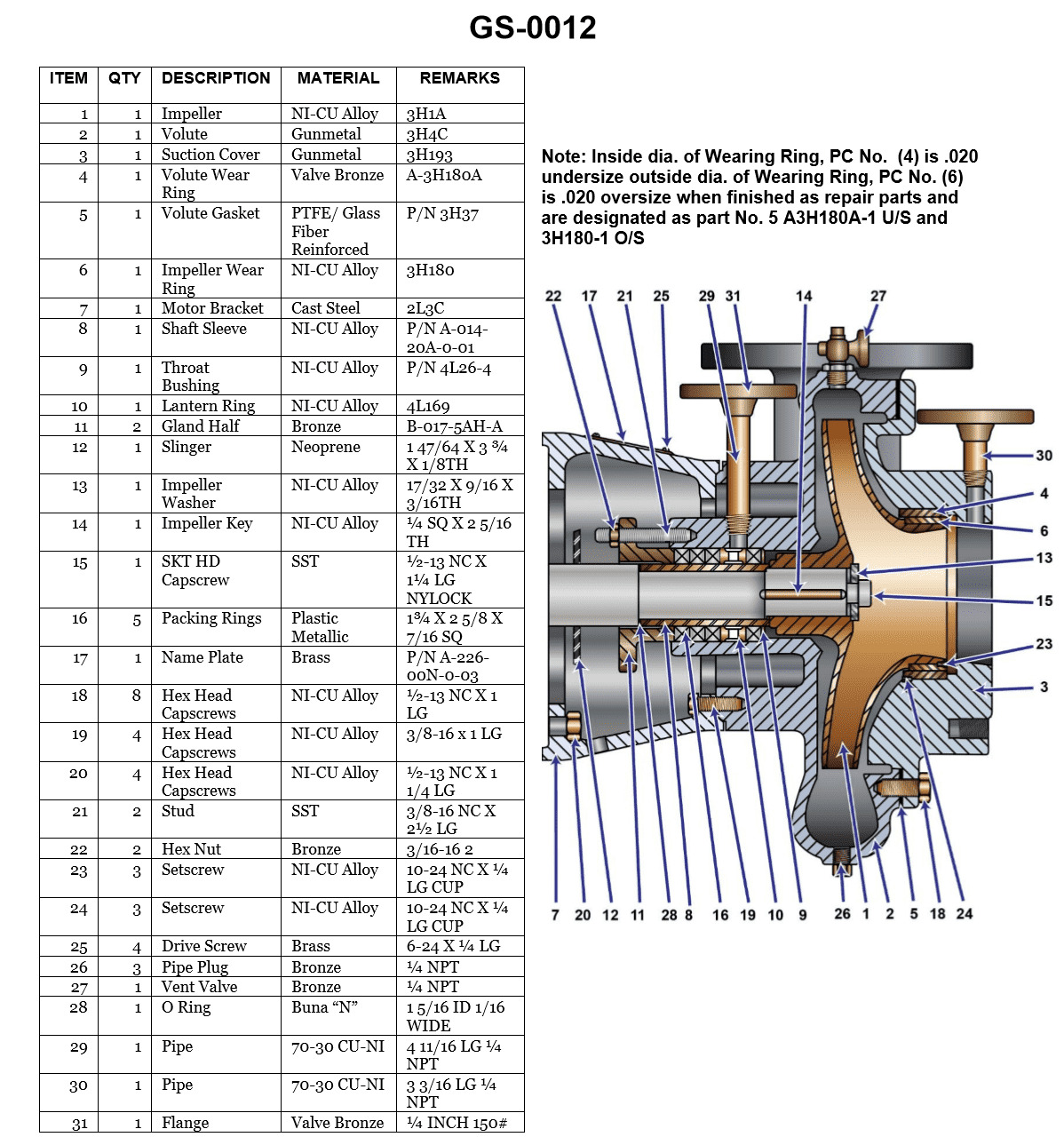
Question: In the illustration shown, an efficient seal is maintained between the suction cover and the volute by __________. Illustration GS-0012
A. good metal-to-metal contact
B. sealant between the two parts
C. an ptfe/glass fiber reinforced gasket
D. compressing the packing rings
The Correct Answer is C ### Why Option C is Correct: An efficient, pressure-tight seal between two major, rigid components like the suction cover and the volute casing of a centrifugal pump is standardly achieved using a **gasket**. The gasket fills microscopic irregularities and conforms to the surfaces when compressed, creating a reliable seal. An **PTFE (Teflon)/glass fiber reinforced gasket** is a common, high-performance material choice for industrial pumps because PTFE offers excellent chemical resistance and low friction, while the glass fibers provide necessary mechanical strength and dimensional stability to withstand the sealing forces and internal pressures. ### Why the Other Options are Incorrect: * **A) good metal-to-metal contact:** While machined surfaces are used, relying solely on metal-to-metal contact (a process known as lapping) to maintain a seal under varying pressures and temperatures between large pump components is generally unreliable and extremely expensive to achieve perfectly. A gasket is required to ensure a leak-proof connection. * **B) sealant between the two parts:** Sealants (like RTV silicone or threadlocker) are flexible compounds that cure in place. While sometimes used in conjunction with gaskets or in low-pressure applications, they are typically not robust enough to be the primary method for sealing the high-pressure, major casing joint between the suction cover and the volute in industrial pumps. A formed gasket is the standard engineering practice. * **D) compressing the packing rings:** Packing rings (or mechanical seals) are used to seal the area where the rotating pump shaft penetrates the casing (the stuffing box). They prevent leakage along the shaft, but they have no function in sealing the static joint between the suction cover and the volute casing.
Question 3
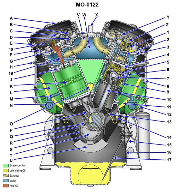
Question: You are assigned as an engineer on a fishing industry factory ship using main propulsion engines of the type shown in the illustration. Assuming that the piston is properly positioned, what statement represents the procedure for inspection of the compression rings while in place inside the engine? Illustration MO-0122
A. The inspection takes place by removing the appropriate cylinder head valve cover and viewing through the resulting opening.
B. The inspection takes place by removing the appropriate oil pan cover and viewing through the resulting opening.
C. It is not possible to inspect the compression rings while in place inside the engine.
D. The inspection takes place by removing the appropriate air box handhole cover and viewing through the resulting opening.
The Correct Answer is D **Explanation for Option D (Correct):** The illustration MO-0122 typically depicts a large, slow-speed, two-stroke diesel engine (common for main propulsion on factory ships). A critical design feature of these engines is the "air box" (or scavenging air manifold) which surrounds the lower part of the cylinder liner. The air box is where compressed scavenging air enters the cylinder through ports cut into the liner wall (when the piston is near bottom dead center). To facilitate maintenance and inspection, these air boxes are equipped with removable covers known as "air box handhole covers." When the piston is correctly positioned (above the scavenging ports), removing these covers allows a direct visual inspection of the piston rings (both compression and oil control rings) via the liner's scavenging ports. This is the standard, practical, and non-invasive procedure for inspecting the rings in this type of engine. **Explanation of Incorrect Options:** * **A) The inspection takes place by removing the appropriate cylinder head valve cover and viewing through the resulting opening.** This is incorrect. The valve cover (or cylinder head inspection cover) allows access to the valve gear (rockers, springs, etc.) on the top of the cylinder. It does not provide any view down the cylinder wall to the piston rings, which are much further down. * **B) The inspection takes place by removing the appropriate oil pan cover and viewing through the resulting opening.** This is incorrect. The oil pan cover (or crankcase inspection door) provides access to the running gear (crankshaft, connecting rod bearings, crosshead). While it allows viewing the underside of the piston skirt and connecting rod, the piston rings are housed high up in the piston grooves and are obscured by the cylinder liner and piston structure from this angle. * **C) It is not possible to inspect the compression rings while in place inside the engine.** This is incorrect. As detailed in the explanation for D, visual inspection of the rings while the engine is assembled is entirely possible and standard procedure by using the air box handhole covers.
Question 3
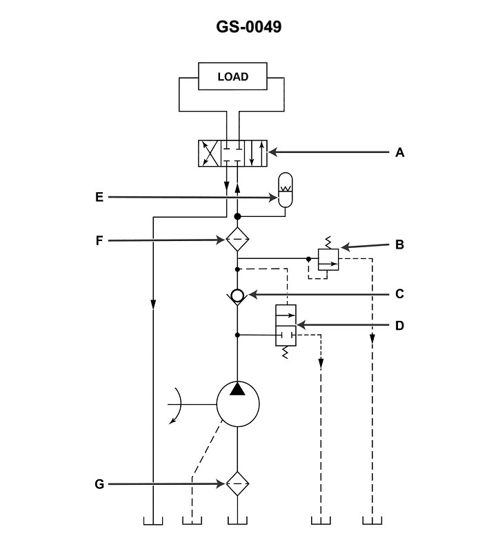
Question: Assuming valve "A" is correctly aligned in the no-flow position as shown with the system in operation, which of the following statements is true? Illustration GS-0049
A. The fixed delivery pump would be stopped automatically by a pressure switch.
B. Valve "D" would normally open before valve "B".
C. Valve "B" would be open before valve "D".
D. Valve "C" would be closed.
The Correct Answer is B **Explanation of Correct Option (B):** The illustration (GS-0049, which depicts a typical hydraulic pressure relief system using a fixed displacement pump) shows a main relief valve system (RV) controlling system pressure. This system consists of a main relief valve (RV) which is remotely piloted by a smaller pilot relief valve (RV-P). * **Valve D** represents the pilot relief valve (RV-P). * **Valve B** represents the main relief valve (RV). In a two-stage relief valve system (pilot-operated relief valve), the pilot valve (D) is a small, spring-loaded valve set to the desired system pressure. When system pressure exceeds this setting, the pilot valve (D) opens first. The opening of the pilot valve (D) allows fluid to flow, creating a pressure imbalance across the main relief valve (B) spool. This pressure imbalance forces the main relief valve (B) to open, dumping the pump's flow back to the tank, thus relieving the system pressure. Therefore, the pilot valve **D** must open to initiate the relief process before the main valve **B** opens completely to handle the high flow. **Valve "D" would normally open before valve "B" is true.** **Explanation of Incorrect Options:** * **A) The fixed delivery pump would be stopped automatically by a pressure switch.** * This is incorrect. The primary function of the relief valve system in a fixed delivery (fixed displacement) pump circuit is to manage excess pressure by dumping flow back to the tank, allowing the pump to continue running without exceeding the maximum system pressure. While some circuits might use pressure switches to shut down the pump for safety/emergency stops, it is not the **normal** function or consequence of the relief valve operation shown when flow is blocked. * **C) Valve "B" would be open before valve "D".** * This is incorrect. As explained above, this system is a pilot-operated relief valve. The pilot valve (D) must open first to actuate the main valve (B). * **D) Valve "C" would be closed.** * This is incorrect. Valve "C" is an isolation or shutoff valve located between the main system line and the pilot relief valve circuit. Assuming the relief valve system is active and correctly installed (as implied by the question), Valve "C" must be open (or removed, if it's a test point) to transmit system pressure to the relief valve circuit (D and B). If Valve "C" were closed, the relief valve system would be isolated and unable to relieve system pressure, potentially leading to catastrophic failure.
Question 4
Question: You are assigned as an engineer on a fishing research vessel using main propulsion engines of the type shown in the illustration. What statement represents the procedure for inspection of the upper cylinder liner bore while in place inside the engine? Illustration MO-0122
A. With the particular piston positioned at BDC and the corresponding oil pan handhole cover removed, inspect the upper liner bore through the scavenging-air ports.
B. With the particular piston positioned at TDC and the corresponding oil pan handhole cover removed, inspect the upper liner bore through the scavenging-air ports.
C. With the particular piston positioned at BDC and the corresponding air box handhole cover removed, inspect the upper liner bore through the scavenging-air ports.
D. With the particular piston positioned at TDC and the corresponding air box handhole cover removed, inspect the upper liner bore through the scavenging-air ports.
The Correct Answer is C ### Explanation of Correct Option (C) Option C is correct because it describes the standard procedure for visually inspecting the upper cylinder liner bore through the scavenging-air ports in a two-stroke engine (the type typically used for main propulsion and often featuring scavenging ports, as implied by the inspection method). 1. **Positioning the Piston at BDC (Bottom Dead Center):** To inspect the upper liner bore, the piston must be moved down to BDC. When the piston is at BDC, the scavenging-air ports are fully uncovered, allowing visual access to the critical wear area of the liner (the upper portion where the rings primarily operate during combustion). 2. **Removing the Air Box Handhole Cover:** The scavenging-air ports are located in the cylinder liner wall and communicate with the surrounding air box (also known as the scavenging belt or receiver). To gain access to the ports for inspection, the handhole covers on the air box must be removed. 3. **Inspecting Through Scavenging-Air Ports:** This is the specific pathway used for visual inspection of the liner condition (e.g., scoring, pitting, wear step) without dismantling the cylinder head or pulling the piston. ### Explanation of Incorrect Options **A) With the particular piston positioned at BDC and the corresponding oil pan handhole cover removed, inspect the upper liner bore through the scavenging-air ports.** * **Incorrect Element:** Removing the **oil pan** handhole cover provides access to the crankcase, connecting rod, and piston skirt from below, but it does not provide access to the **scavenging-air ports**, which are located on the cylinder liner wall, separate from the crankcase. **B) With the particular piston positioned at TDC and the corresponding oil pan handhole cover removed, inspect the upper liner bore through the scavenging-air ports.** * **Incorrect Elements:** * **Piston Position:** When the piston is at **TDC (Top Dead Center)**, it covers the scavenging-air ports, making inspection impossible. The piston must be at BDC. * **Handhole Cover:** Access requires removal of the **air box** cover, not the oil pan cover. **D) With the particular piston positioned at TDC and the corresponding air box handhole cover removed, inspect the upper liner bore through the scavenging-air ports.** * **Incorrect Element:** The piston must be positioned at **BDC (Bottom Dead Center)** to fully expose the scavenging-air ports and the critical upper section of the liner for inspection. Positioning it at TDC blocks the ports.
Question 9
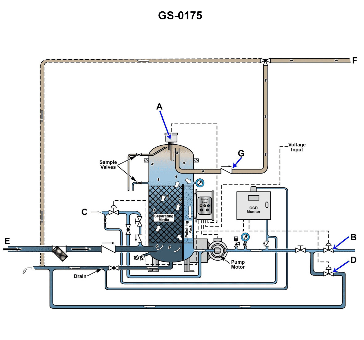
Question: The line labeled "E", as shown in the illustration, would be identified as the ______. Illustration GS-0175
A. clean water inlet line
B. waste oil outlet line
C. oily bilge water inlet line
D. processed water outlet line
The Correct Answer is C **Explanation for Option C (oily bilge water inlet line):** In systems related to treating oily water (such as an Oily Water Separator or Bilge Water Treatment Unit, which Illustration GS-0175 likely depicts), the line labeled "E" typically represents the path through which the source material—the contaminated water requiring processing—is introduced into the system. Bilge water is the water that collects in the lowest parts of a ship, and it frequently contains oil, grease, cleaning agents, and suspended solids, making it "oily bilge water." Therefore, Line E would be the **oily bilge water inlet line** bringing the untreated mixture into the separation unit. **Explanation for Why Other Options Are Incorrect:** * **A) clean water inlet line:** This is incorrect. While clean water may sometimes be used in these systems (e.g., for flushing or cleaning), the primary and most prominent inlet line is for the contaminated fluid (the bilge water). If it were a clean water inlet, it would typically be labeled for service or utility water, not the main process flow labeled "E" in this context. * **B) waste oil outlet line:** This is incorrect. The waste oil (the separated contaminant) would be an *outlet* line, typically located high on the separator unit, leading away from the system to a sludge tank or waste holding tank. An inlet line is where the mixture enters the system. * **D) processed water outlet line:** This is incorrect. The processed (treated and cleaned) water would be an *outlet* line leading away from the separator, usually discharged overboard (if compliant) or sent to a holding tank. It would not be an inlet line like "E".
Question 10
Question: Referring to the illustration, suppose after initiating the oil discharge mode, the oily-water separator fails to come out of the oil discharge mode in a timely fashion. Cracking open the upper sampling valve reveals the presence of oil exiting under positive pressure. What is most likely the cause? Illustration GS-0175
A. The lower oil/water interface detection probe fails to initiate the oil discharge mode.
B. The upper oil/water interface detection probe fails to end the oil discharge mode.
C. The oil discharge check valve fails to open, and as a result no oil actually discharges.
D. The clean water supply solenoid fails to open, and as a result provides no discharge pressure.
The Correct Answer is C. ### Why Option C is Correct The scenario describes a situation where the oily-water separator (OWS) is stuck in the oil discharge mode ("fails to come out of the oil discharge mode in a timely fashion"). Crucially, cracking open the upper sampling valve reveals oil exiting under positive pressure. When the OWS enters the oil discharge phase, the separated oil should be discharged from the top of the separator unit. If the **oil discharge check valve fails to open**, the separated oil has nowhere to go. This blockage prevents the oil layer from being removed. Since the separator continues to operate and separate oil (or perhaps is still pressurizing the unit), the pressure will build up, and the oil level will rise and remain high, keeping the system in the oil discharge state. The presence of oil exiting the upper sampling valve under positive pressure confirms that the system is pressurized and that oil has accumulated and is trapped inside the separation chamber (i.e., it is not discharging). Therefore, the failure of the oil discharge check valve to open is the most likely mechanical reason for the system being stuck in discharge mode with pressurized oil present. ### Why Other Options Are Incorrect **A) The lower oil/water interface detection probe fails to initiate the oil discharge mode.** If the lower probe failed to initiate the mode, the OWS would never enter the oil discharge cycle in the first place. The scenario explicitly states that the OWS *after initiating* the oil discharge mode, fails to come out of it. This indicates the initiation was successful, making option A incorrect. **B) The upper oil/water interface detection probe fails to end the oil discharge mode.** The function of the upper probe is indeed to signal the end of the oil discharge mode (usually indicating that the oil layer has been depleted and water has reached the upper probe). If the probe failed electronically (e.g., stuck "on"), the system might fail to switch out of discharge mode. However, the scenario also includes the physical evidence: oil exiting the upper sampling valve under positive pressure. If the upper probe failed electronically, but the oil was actually discharging, the pressure and oil accumulation described would not be present. The most fundamental reason for the failure to end the discharge mode while pressurized oil is present is a failure of the discharge path (C). **D) The clean water supply solenoid fails to open, and as a result provides no discharge pressure.** Clean water is often used to flush the unit or provide motive pressure for discharge in certain OWS designs. If the clean water supply failed to open, there might be insufficient pressure to push the oil out. However, the scenario states that oil is exiting the sampling valve *under positive pressure*. This indicates that sufficient pressure *is* present within the unit, whether it's operating pressure or residual pressure, contradicting the premise that the failure is due to a lack of pressure. The problem is not the lack of pressure, but the blockage preventing discharge despite the pressure.
Question 11
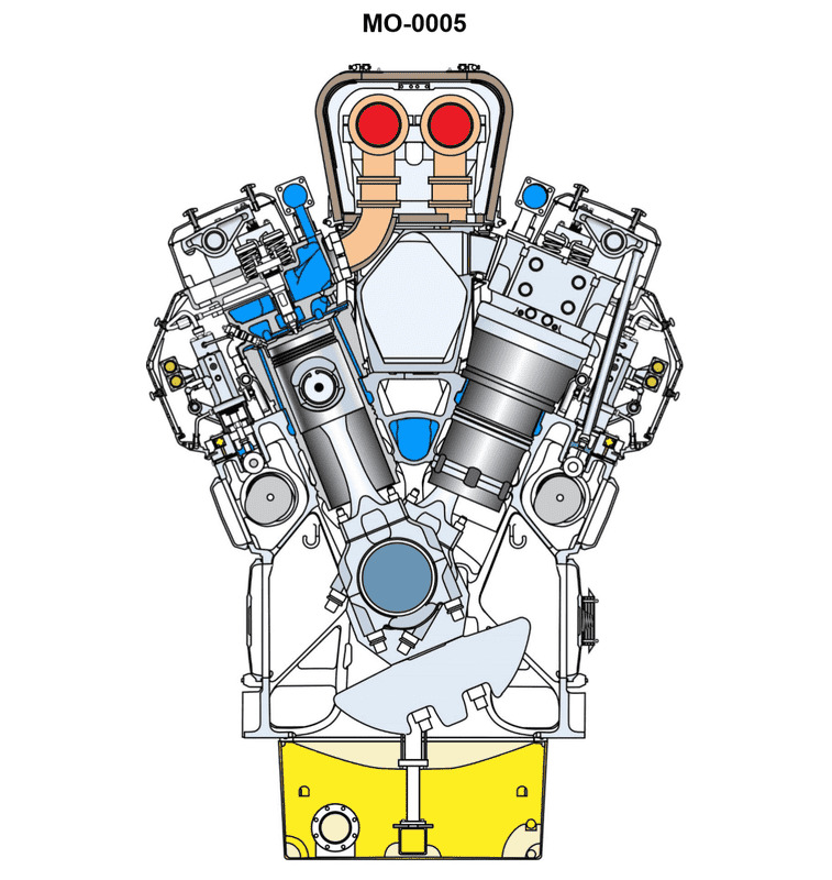
Question: The uninspected fishing trawler to which you are assigned is fitted with main propulsion diesel engines of the type shown in the illustration. In terms of valve operating gear, cylinder liner type, and connecting rod type, what statement is true? Illustration MO-0005
A. This is a pushrod operated overhead valve engine, with jacketed cylinder liners and articulated connecting rods.
B. This is a pushrod operated overhead valve engine, with wet cylinder liners and conventional connecting rods.
C. This is an overhead cam engine, with wet cylinder liners and conventional connecting rods.
D. This is an overhead cam engine, with jacketed cylinder liners and marine-type connecting rods.
The Correct Answer is B **Explanation for Option B (Correct):** Option B states that the engine is a pushrod operated overhead valve engine, with wet cylinder liners and conventional connecting rods. This description is characteristic of common medium-speed, heavy-duty marine propulsion diesel engines often found in fishing trawlers (like the one implied by Illustration MO-0005, which typically depicts a standard four-stroke marine diesel). 1. **Pushrod Operated Overhead Valve Engine:** Most engines of this size and type utilize a camshaft located lower in the engine block (often near the crankshaft), using pushrods and rocker arms to operate the valves in the cylinder head. This configuration is simpler and more robust for medium-speed applications than complex overhead camshaft (OHC) designs (Options C and D). 2. **Wet Cylinder Liners:** Wet liners are surrounded directly by the engine coolant. This design allows for better heat transfer and easier replacement during major overhauls, making them standard for large, continuously rated marine diesels. 3. **Conventional Connecting Rods:** Conventional connecting rods (typically single-piece forged steel rods with bolted big-end caps) are standard for medium-speed, trunk-piston engines where the rod connects the piston directly to the crankshaft journal. They are contrasted with articulated or marine-type connecting rods, which are used in much larger crosshead engines or specialized V-engines. Since the engine depicted is a standard trunk-piston diesel suitable for a trawler, conventional rods are used. **Explanation for Incorrect Options:** **A) This is a pushrod operated overhead valve engine, with jacketed cylinder liners and articulated connecting rods.** * **Incorrect Feature: Jacketed Cylinder Liners:** Jacketed liners are typically synonymous with "dry liners," which are pressed into the block and cooled indirectly. Wet liners are standard for this application. * **Incorrect Feature: Articulated Connecting Rods:** Articulated rods are a specific design used primarily in V-type engines or some large engines where a master rod connects the piston and a slave rod pivots off the master rod. Conventional connecting rods are standard for in-line engines of this type. **C) This is an overhead cam engine, with wet cylinder liners and conventional connecting rods.** * **Incorrect Feature: Overhead Cam (OHC):** While OHC engines exist in marine applications, pushrod designs are generally more common, robust, and cost-effective for medium-speed marine trunk-piston diesels of this size. OHC is characteristic of higher-speed or smaller engines. **D) This is an overhead cam engine, with jacketed cylinder liners and marine-type connecting rods.** * **Incorrect Feature: Overhead Cam (OHC):** As explained for C, pushrod operation is more likely. * **Incorrect Feature: Jacketed Cylinder Liners:** Wet liners are standard. * **Incorrect Feature: Marine-type Connecting Rods:** "Marine-type" connecting rods (also called crosshead connecting rods) are specific to very large, slow-speed two-stroke engines that utilize a crosshead mechanism to separate the piston side loads from the connecting rod. The engine described (suitable for a fishing trawler) is a medium-speed trunk-piston engine, which uses conventional rods.
Question 11
Question: Referring to the illustration, suppose while in the oil separation processing mode, the oil content detector display screen shows 17.9 ppm and the oily-water separator is discharging back to the bilge water holding tank for recirculation. What is most likely the cause? Illustration GS-0175
A. The bilge water holding tank level is excessively high resulting in a high-level alarm.
B. The oily-water separator bilge suction strainer is excessively clogged.
C. The bilge water holding tank contents is excessively contaminated with oil.
D. The oily-water separator service pump is excessively worn.
The Correct Answer is C **Explanation for Option C (Correct Answer):** The scenario states two critical pieces of information: 1. The oil content detector (OCD) display screen shows **17.9 ppm** (parts per million). 2. The oily-water separator (OWS) is discharging back to the bilge water holding tank for **recirculation**. Regulations (like IMO MEPC 107(49)) typically require that processed water discharged overboard must not exceed 15 ppm. If the detector reads above the set threshold (which is usually set at or slightly below 15 ppm, or potentially a higher internal alarm limit depending on the system design, but certainly indicating high contamination), the system automatically triggers an alarm and diverts the discharge flow away from the overboard line and back into the bilge holding tank (recirculation mode) to prevent illegal discharge. A reading of 17.9 ppm is too high for legal discharge. This high reading directly indicates that the water entering or leaving the final stage of the separator is still heavily contaminated with oil. The most direct and likely cause for the final effluent to be heavily contaminated is that the **input source (the bilge water holding tank contents) is excessively contaminated with oil**, overwhelming the separation capabilities of the OWS system. **Explanation for Other Options (Incorrect):** * **A) The bilge water holding tank level is excessively high resulting in a high-level alarm.** While a high-level alarm may stop the transfer pump, it does not directly cause the final effluent to register 17.9 ppm. The 17.9 ppm reading is a quality (contamination) issue, not a quantity (level) issue. * **B) The oily-water separator bilge suction strainer is excessively clogged.** A clogged strainer would restrict flow (reduce throughput), potentially reducing the efficiency of the pump or causing the separator to trip on low flow/pressure, but it would not inherently increase the PPM reading of the processed water. If anything, reduced flow might slightly aid separation time, although the primary symptom of clogging is reduced flow volume. The high PPM reading is a failure of separation quality, not flow rate. * **D) The oily-water separator service pump is excessively worn.** A worn pump would primarily result in reduced flow or reduced pressure to the separator, which might make the separation process less effective if the flow falls outside the optimal range. However, this is a less direct cause than the input contamination being too high. Typically, if the OWS is functioning, the most critical factor determining the failure to meet the 15 ppm standard is the volume and concentration of oil presented to the system (i.e., the state of the bilge water holding tank contents). If the OWS is operating but failing the quality check, the primary source of the problem is usually the input load exceeding capacity.
Question 12
Question: The fishing industry line vessel to which you are assigned is fitted with main propulsion diesel engines of the type shown in the illustration. In terms of valve operating gear, cylinder liner type, and connecting rod type, what statement is true? Illustration MO-0122
A. This is an overhead cam engine, with wet cylinder liners, and marine-type connecting rods.
B. This is an overhead cam engine, with jacketed cylinder liners and hinged-strap, fork-and-blade connecting rods.
C. This is a pushrod operated overhead valve engine, with jacketed cylinder liners and conventional connecting rods.
D. This is a pushrod operated overhead valve engine, with wet cylinder liners and hinged-strap, fork-and- blade connecting rods.
The Correct Answer is B ### Explanation of Why Option B is Correct Option B states: "This is an overhead cam engine, with jacketed cylinder liners and hinged-strap, fork-and-blade connecting rods." This combination accurately describes the design features of many high-speed or medium-speed V-type diesel engines commonly used for main propulsion in fishing vessels (which the referenced illustration, MO-0122, is designed to represent). 1. **Overhead Cam Engine (OHC):** Medium-speed V-configuration engines often utilize an overhead camshaft (or very short cam-to-valve linkage) to improve valve timing and reduce inertia inherent in long pushrod systems, allowing for higher engine RPM. 2. **Jacketed Cylinder Liners:** This term refers to cylinder liners that are supported within a structure where the cooling water circulates around the outer structure (the cylinder block/jacket), making them "dry liners." This is typical for high-output, compact V-engines, as opposed to "wet liners" where the cooling water is in direct contact with the liner exterior. 3. **Hinged-Strap, Fork-and-Blade Connecting Rods:** This is the definitive characteristic of many large V-type engines. This complex assembly allows two connecting rods (one from each bank of the V) to share a single, narrow crankpin journal. The "fork" rod straddles the journal, while the "blade" rod (which often uses a hinged strap to facilitate assembly) fits precisely within the gap of the fork rod. This arrangement ensures proper geometric balance and shared journal loading in V-engines. ### Why Other Options Are Incorrect **A) This is an overhead cam engine, with wet cylinder liners, and marine-type connecting rods.** * **Incorrect Feature:** The engine type depicted, utilizing the highly specific fork-and-blade rod design, typically employs dry (jacketed) liners, not wet liners. Furthermore, "marine-type connecting rods" is too vague and does not specify the required fork-and-blade geometry. **C) This is a pushrod operated overhead valve engine, with jacketed cylinder liners and conventional connecting rods.** * **Incorrect Feature:** If the engine uses the specialized V-configuration requiring hinged-strap/fork-and-blade rods, it cannot use "conventional connecting rods" (which sit side-by-side or use a master/slave setup, but not the specific fork/blade design necessary to share a narrow journal). **D) This is a pushrod operated overhead valve engine, with wet cylinder liners and hinged-strap, fork-and- blade connecting rods.** * **Incorrect Feature:** The use of "wet cylinder liners" is generally incorrect for the type of high-output, medium-speed V-engine that requires the "hinged-strap, fork-and-blade" rod geometry. These designs favor jacketed (dry) liners for structural integrity and thermal management.
Question 13
Question: The mollusc dredger to which you are assigned is fitted with generator set drive engines as shown in the illustration. What statement is true in terms of the combustion chamber design? Illustration MO-0005
A. The engine uses turbulence chambers with a hemispherical fire-deck.
B. The engine uses an open type combustion chamber with a hemispherical fire-deck.
C. The engine uses an open type combustion chamber with a flat fire-deck.
D. The engine uses pre-combustion chambers with a flat fire-deck.
The Correct Answer is C **Explanation for C being correct:** The question refers to a generator set drive engine for a mollusc dredger, likely a common marine or heavy-duty diesel engine used in industrial applications. While the specific illustration MO-0005 is not provided, the majority of modern medium- to high-speed, direct-injection (DI) diesel engines used for power generation (like those from manufacturers such as CAT, Cummins, MAN, etc.) utilize an **open type combustion chamber**. This design is characterized by the fuel being injected directly into the main volume of air compressed within the cylinder. Furthermore, these engines typically feature a **flat cylinder head (fire-deck)** with the combustion bowl or cavity formed entirely within the piston crown. This combination maximizes thermal efficiency, improves starting characteristics, and is standard for high-power-density DI engines. Therefore, the statement "The engine uses an open type combustion chamber with a flat fire-deck" is the most accurate description for a modern generator set engine. **Why the other options are incorrect:** * **A) The engine uses turbulence chambers with a hemispherical fire-deck.** This describes an indirect injection (IDI) system, specifically a swirl chamber (turbulence chamber). IDI engines generally have lower thermal efficiency and are less common in modern, high-power generator sets compared to DI engines. A hemispherical fire-deck is characteristic of older or specialized gasoline or two-stroke engines, not typically modern four-stroke diesel gensets. * **B) The engine uses an open type combustion chamber with a hemispherical fire-deck.** While the open type chamber (DI) is correct, a hemispherical fire-deck implies the piston crown and cylinder head form a sphere, which is incompatible with the standard flat cylinder head design used in modern DI engines where the combustion bowl is centered in the piston. * **D) The engine uses pre-combustion chambers with a flat fire-deck.** A pre-combustion chamber is another type of indirect injection (IDI) design. Like turbulence chambers (Option A), pre-combustion chambers are less efficient, produce lower specific output, and are rarely used in new heavy-duty generator set engines compared to the open (DI) design.
Question 14
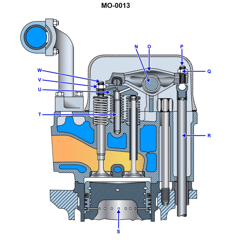
Question: The uninspected fishing trawler to which you are assigned is fitted with auxiliary engines as partly shown in the illustration. What statement is true concerning the valve guide and valve seat arrangements? Illustration MO-0013
A. The valve guides are replaceable inserts, and the valve seats are integral (non-replaceable).
B. The valve guides and the valve seats are both replaceable inserts.
C. The valve guides are integral (non-replaceable), and the valve seats are replaceable inserts.
D. The valve guides and the valve seats are both integral (non-replaceable).
The Correct Answer is B **Explanation for Option B (Correct Answer):** In modern medium-to-large diesel engines, such as those typically used as auxiliary engines on fishing trawlers, both the valve guides and the valve seats are commonly designed as replaceable inserts. 1. **Valve Seats:** Valve seats (especially exhaust valve seats, which experience high wear due to extreme heat and corrosive gases) are almost universally made as replaceable inserts (seat rings). These inserts are typically made of specialized, hard, wear-resistant alloys and are pressed or shrunk-fit into the cylinder head. This allows for easy servicing, inspection, and replacement when wear limits are reached, preserving the expensive cylinder head casting. 2. **Valve Guides:** Valve guides, which align the valve stem and guide its movement, also suffer significant wear over time due to friction and high temperatures. While some smaller, older engines may have integral guides, standard engineering practice for modern, reliable auxiliary marine engines is to use **replaceable valve guide inserts**. This facilitates efficient maintenance and prevents having to scrap the entire cylinder head assembly just because the guide is worn. Therefore, for the efficient, repairable design expected in marine auxiliary power plants, both the valve guides and valve seats are typically replaceable inserts. **Explanation of Incorrect Options:** * **A) The valve guides are replaceable inserts, and the valve seats are integral (non-replaceable).** This is incorrect. While guides are often replaceable, valve seats are almost never made integral in high-performance or high-wear applications like diesel cylinder heads because they wear out faster than the surrounding metal, and making them integral would require replacing the entire cylinder head when wear limits are reached. * **C) The valve guides are integral (non-replaceable), and the valve seats are replaceable inserts.** This is incorrect. While the valve seats being replaceable inserts is standard, the valve guides being integral is less common in modern, heavy-duty marine engines due to the desirability of easy replacement during overhaul. * **D) The valve guides and the valve seats are both integral (non-replaceable).** This is significantly incorrect for modern medium/large diesel auxiliary engines. Both components experience heavy wear and must be replaceable to ensure the cylinder head has a long service life and maintenance is practical.
Question 15
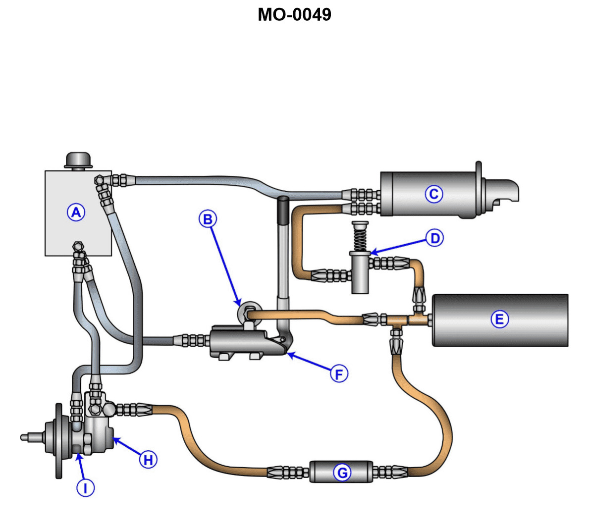
Question: The various auxiliary diesel engines fitted on your fishery research vessel may employ a variety of different starting systems. What type of starting system is shown in the illustration? Illustration MO-0049
A. Gas engine power operated system.
B. Pneumatic power operated system.
C. Hydraulic power operated system.
D. Electric power operated system.
The Correct Answer is C **Why Option C ("Hydraulic power operated system.") is correct:** The starting system shown in the illustration MO-0049 typically depicts components characteristic of a hydraulic starting system. These systems utilize a high-pressure hydraulic pump (driven by an electric motor or manually), an accumulator to store pressurized fluid, control valves, and a hydraulic motor (starter) that engages the engine flywheel. Hydraulic systems are often favored for medium-sized auxiliary engines, especially in marine environments, because they offer high torque output, reliability, and are intrinsically spark-free, making them safe for potentially hazardous areas. **Why the other options are incorrect:** * **A) Gas engine power operated system:** This option describes systems where a separate, small internal combustion engine (often running on gasoline or LPG) is used to crank the main engine. While historically used, this is a distinct method not represented by the typical components (pump, accumulator, hydraulic motor) usually implied by such illustrations. * **B) Pneumatic power operated system:** This system (often called Air Start) uses high-pressure compressed air stored in reservoirs. While common on large main engines and some auxiliary engines, the illustration's components (especially the pump and accumulator if clearly visible) would be inconsistent with a pure air-only system, which primarily features air reservoirs, reducing valves, and an air distributor/motor. * **D) Electric power operated system:** Electric starting uses heavy-duty batteries and a large DC starter motor. While the depicted system might include an electric motor to drive the hydraulic pump, the overall system architecture—relying on high-pressure fluid storage (accumulator)—defines it as hydraulic, not purely electric starting, where the starter motor connects directly to the battery bank.
Question 16
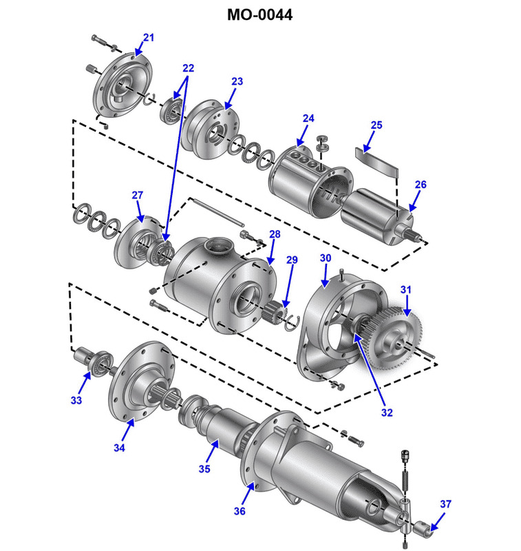
Question: The various auxiliary diesel engines fitted on your uninspected fishing trawler may employ a variety of different cranking methods for engine starting. What type of cranking method is shown in the illustration? Illustration MO-0044
A. Hydraulic cranking motor.
B. Air cranking motor.
C. Gasoline engine cranking motor.
D. Electric cranking motor.
The Correct Answer is B **Explanation for B (Air cranking motor.)** An air cranking motor (or pneumatic starter) uses compressed air, stored in a reservoir tank, to drive a turbine or vane motor. This system is highly common on auxiliary diesel engines found on fishing trawlers and other large marine vessels because it provides extremely high torque necessary to turn over large engines, is very reliable, and avoids the maintenance and complexity associated with large battery banks dedicated solely to starting (as required by electric starters). The illustration (MO-0044) would typically depict the robust housing of the pneumatic motor with visible high-pressure air supply lines connected, clearly differentiating it from electrical components or hydraulic lines. **Why the other options are incorrect:** * **A) Hydraulic cranking motor:** A hydraulic starter uses pressurized oil or fluid from an accumulator to power the starter motor. The visible connections would be high-pressure hydraulic hoses and return lines, and the system requires a separate pump/reservoir structure, which looks distinctly different from the air piping used in pneumatic systems. * **C) Gasoline engine cranking motor:** This method involves a small, separate gasoline engine (sometimes called a "pony motor") that is mechanically coupled to crank the main diesel engine. The illustration would show a complete, small internal combustion engine assembly mounted adjacent to the main engine, which is visually obvious and unlike the compact motor unit of an air starter. * **D) Electric cranking motor:** An electric starter relies on heavy-gauge electrical cables and a solenoid to power a DC motor. The illustration would show the distinctive solenoid housing and the large electrical terminals, lacking the necessary large-diameter piping associated with compressed air delivery.
Question 17
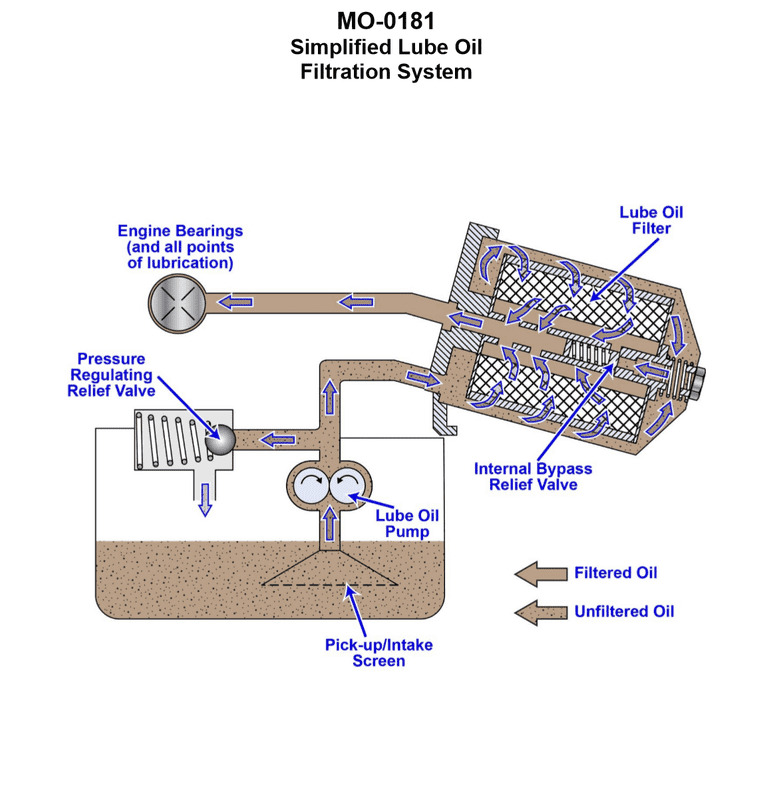
Question: The diesel generator engines onboard your mollusc dredger use a lubricating oil filtration scheme as shown in the illustration. What type of filtration system is illustrated? Illustration MO-0181
A. Full-flow filtration
B. Sump filtration
C. Bypass filtration
D. Shunt filtration
The Correct Answer is A **Explanation for Option A (Full-flow filtration):** Full-flow filtration is the correct answer because, in this system, **100% of the lubricating oil being pumped to the engine bearings and vital components passes through the filter element before reaching those points.** The illustration, MO-0181 (assuming a standard representation of diesel engine oil systems), typically shows the oil pump drawing oil from the sump and pushing it directly through the main oil cooler and filter before it enters the engine's main oil gallery. This ensures that all contaminants that could damage the engine are removed instantaneously from the main flow path, providing immediate protection to critical moving parts. **Why the other options are incorrect:** * **B) Sump filtration:** This term is generally used to describe the location of the oil intake screen (suction strainer) in the oil pan (sump), which is designed to prevent large debris from entering the oil pump. It is not a complete filtration system description. The primary filtration occurs after the pump. * **C) Bypass filtration:** A bypass system (or auxiliary system) only filters a small percentage (typically 5–10%) of the total oil flow at any given time, using a high-efficiency filter to remove very fine particles and soot. The oil is often returned directly to the sump, bypassing the main oil gallery. This system is used *in addition* to, but not *instead of*, the main full-flow filter. * **D) Shunt filtration:** This term is sometimes used interchangeably with bypass filtration or partial-flow filtration, describing a system where only a portion of the oil is filtered, but it is not the standard industrial term for the primary filtration loop that protects the engine immediately.
Question 18
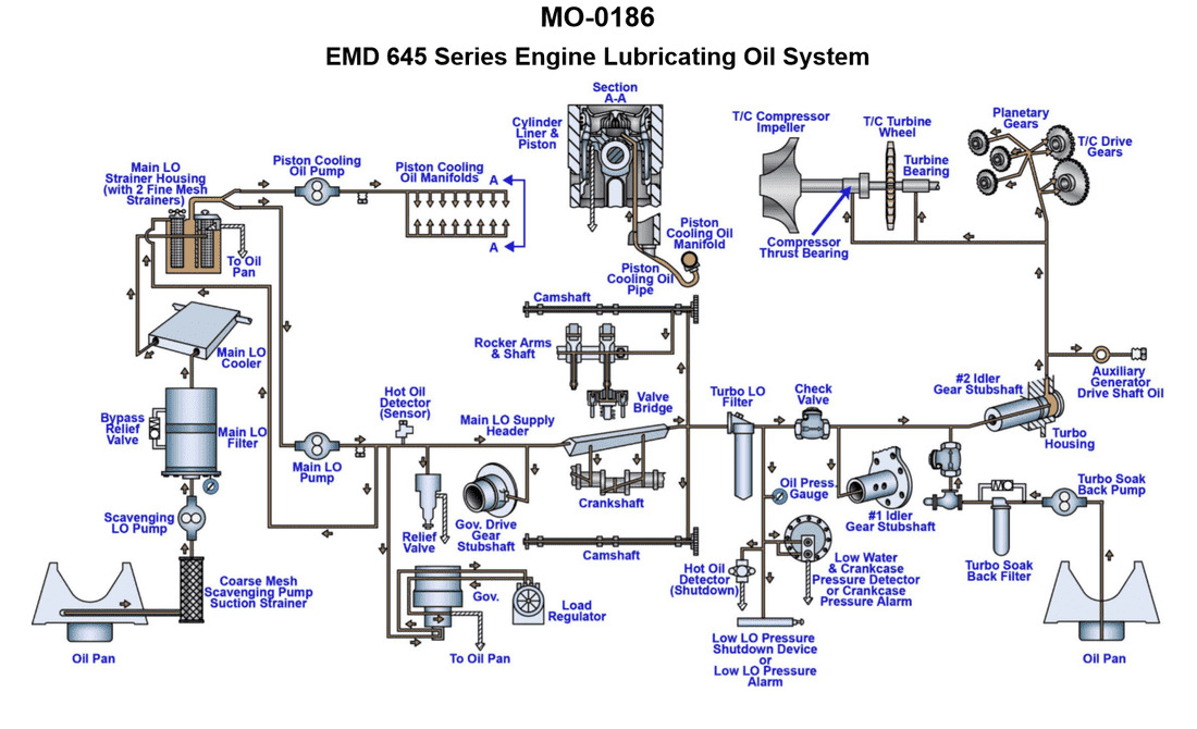
Question: The main propulsion engines onboard your fishery research vessel use a lubricating oil system as shown in the illustration. Under what circumstances will the turbo soak-back pump operate? Illustration MO-0186
A. It will run for a period of time after engine shutdown only.
B. It will operate at all times while the engine is running.
C. It will run for period of time before engine start-up and after engine shutdown.
D. It will run for a period of time prior to engine start-up only.
The Correct Answer is C ### Explanation of the Correct Answer (C) The turbo soak-back pump (or turbo auxiliary pump) is designed to ensure the turbocharger's bearings are properly lubricated and cooled during critical phases of engine operation, specifically during start-up and shutdown, when the main engine-driven lube oil pump may not be providing adequate pressure or flow, or when the turbocharger is still extremely hot after the engine has stopped. 1. **Before Engine Start-up (Pre-lubrication):** Running the soak-back pump briefly before the engine starts ensures that the turbocharger bearings are pre-lubricated. This is crucial because the turbocharger spins at extremely high speeds immediately upon engine ignition, and waiting for the main lube oil pump to build sufficient pressure could cause damage due to dry running. 2. **After Engine Shutdown (Soak-back/Post-cooling):** When the engine stops, the main oil pump stops immediately, but the turbocharger rotor continues to spin (coast down) due to inertia, and the turbocharger housing remains extremely hot (heat soak). The soak-back pump runs for a predetermined period (e.g., 5 to 30 minutes) after shutdown to continuously circulate cooler oil through the bearings. This removes residual heat (preventing carbonization of oil inside the bearings) and provides lubrication until the rotor stops spinning completely, thus protecting the high-speed bearings from heat damage. Therefore, the pump is required to run both before start-up and after shutdown. ### Explanation of Incorrect Options **A) It will run for a period of time after engine shutdown only.** This is partially correct (the post-shutdown operation is essential for cooling), but it ignores the equally important pre-lubrication function required before engine start-up to prevent dry-running wear. **B) It will operate at all times while the engine is running.** While the turbocharger needs lubrication constantly, this specific auxiliary/soak-back pump typically does not run while the engine is running. When the engine is operating, the **main engine-driven lube oil pump** provides sufficient flow and pressure to lubricate the turbocharger (often 4 to 6 bar), making the auxiliary soak-back pump redundant during normal operation. **D) It will run for a period of time prior to engine start-up only.** This is partially correct (the pre-lubrication function is necessary), but it fails to account for the most common and crucial function: the post-shutdown cooling/soak-back period required to prevent heat damage to the turbocharger bearings.
Question 20
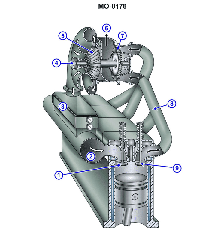
Question: The mollusc dredger to which you are assigned has diesel generator engines fitted with intake and exhaust systems as shown in the illustration. What type of turbo charging configuration is used? Illustration MO-0176
A. Constant pressure turbo charging
B. Boost-controlled turbo charging
C. Pulse turbo charging
D. 2-stage turbo charging
The Correct Answer is C ### 2. Explanation for Option C ("Pulse turbo charging") Pulse turbo charging (or pressure pulse turbo charging) is characterized by the manifold being divided into smaller, shorter sections that group cylinders based on their firing order. These separate sections lead directly to the turbine, often utilizing a multi-entry turbine casing. The primary purpose of this configuration is to preserve the high kinetic energy (pressure pulse) created immediately after the exhaust valve opens. By keeping the manifolds small and segregated, the energy in the pressure wave is not damped by interfering pulses from other cylinders. This system provides: 1. **Rapid Acceleration/Response:** The strong initial pulse provides immediate energy to spin up the turbocharger quickly. 2. **Good Efficiency at Low Load:** Unlike constant pressure systems, pulse charging maintains good efficiency and boost pressure even when the engine is operating at partial loads, which is essential for dredger operations that require frequent power changes and maneuvering. Since marine diesel generators, especially those operating under variable load conditions common on vessels like dredgers, historically prioritize low-load efficiency and rapid response, the illustration (MO-0176) would typically show the characteristic divided manifold structure associated with pulse charging. ### 3. Explanation for Incorrect Options **A) Constant pressure turbo charging:** This configuration uses a large, common exhaust manifold that collects the gas from all cylinders before it enters the turbine at a relatively steady pressure. While highly efficient at maximum load and continuous speed, it is inefficient and exhibits poor turbocharger response at low loads. If the illustration showed a single, large manifold, this would be the correct answer, but for systems prioritizing response (like those on variable-speed dredgers), pulse charging is usually depicted. **B) Boost-controlled turbo charging:** This is not a description of the core turbocharging configuration (manifold design). It is a method of controlling the maximum pressure delivered by the compressor, typically using a wastegate or variable geometry turbine (VGT). The fundamental arrangement of the exhaust manifold leading to the turbine would still be either pulse or constant pressure. **D) 2-stage turbo charging:** This system involves two separate turbochargers working in series (a low-pressure stage followed by a high-pressure stage) to achieve extremely high compression ratios. This configuration is highly complex and usually reserved for modern, high-performance engines needing maximum power density. It would be highly recognizable in the illustration due to the two distinct sets of compressors and turbines. Standard marine medium-speed diesel generators usually use single-stage turbocharging.
Question 21
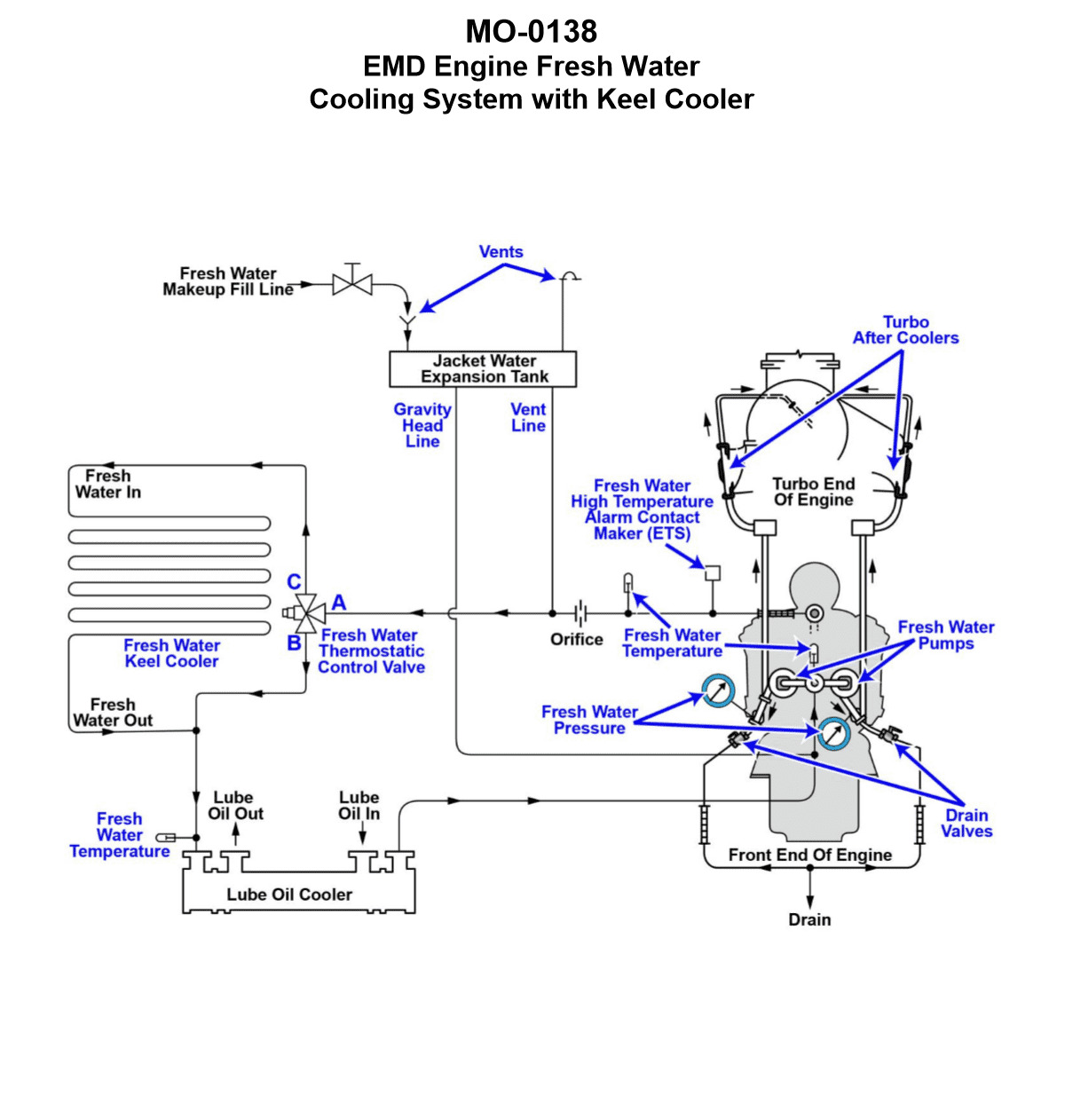
Question: The freshwater cooling systems serving the main engines of the fishery research vessel to which you are assigned are arranged as shown in the illustration. What statement best describes the arrangement of the freshwater keel cooler shown in the system diagram? Illustration MO-0138
A. The keel cooler is mounted on the outside of the hull below the water line
B. The keel cooler is mounted on the inside of the hull above the water line
C. The keel cooler is mounted on the inside of the hull below the water line
D. The keel cooler is mounted on the outside of the hull above the water line
The Correct Answer is A. **Why option A is correct:** A keel cooler is a type of heat exchanger used primarily on vessels. It is designed to dissipate heat from the engine's closed-loop freshwater cooling system directly into the surrounding seawater. To function effectively, the keel cooler must be in constant, direct contact with the maximum volume of cooling medium (the seawater). Therefore, it is always mounted externally, directly onto the hull structure, and specifically **below the water line** where it is fully submerged. **Why other options are incorrect:** * **B) The keel cooler is mounted on the inside of the hull above the water line:** If mounted inside the hull, it would be an internal heat exchanger (like a plate heat exchanger) cooled by pumped seawater, not a keel cooler. If mounted above the water line, it would be exposed to air, not water, making it useless for transferring heat into the sea. * **C) The keel cooler is mounted on the inside of the hull below the water line:** Although below the water line, mounting it inside the hull would require the heat to transfer through the hull material (which is a poor conductor of heat compared to direct water contact) and would classify it as a box cooler or similar internal heat exchanger, not a traditional external keel cooler. * **D) The keel cooler is mounted on the outside of the hull above the water line:** Mounting it outside is correct, but mounting it above the water line means it would be cooled primarily by air (and occasional spray), severely limiting its cooling capacity and rendering it ineffective for marine engine cooling.
Question 22
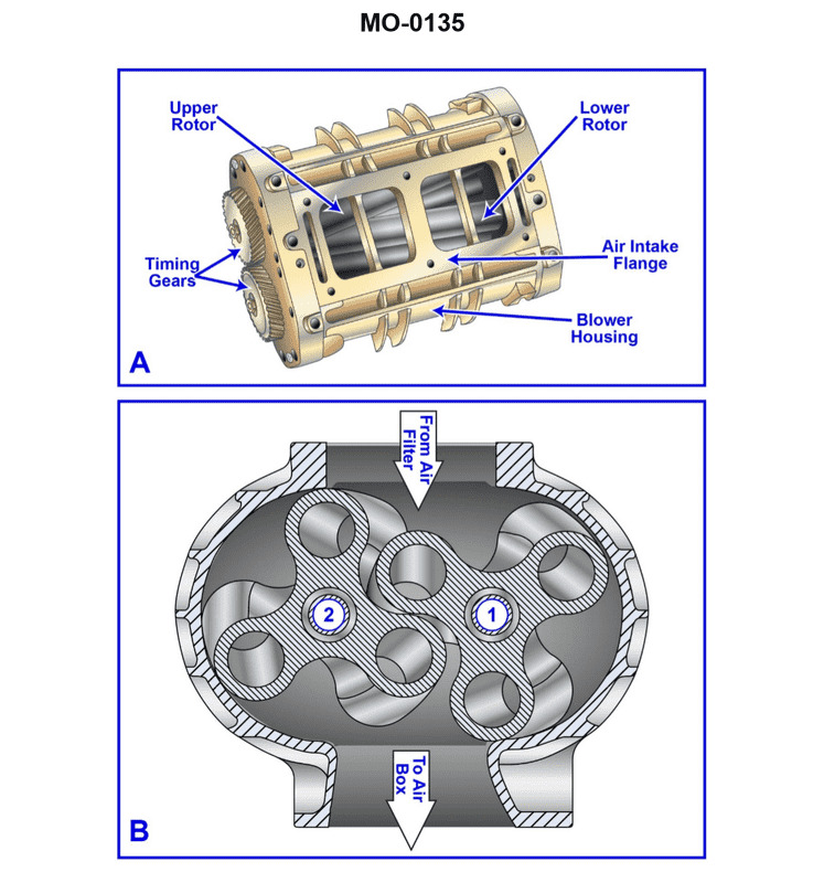
Question: The auxiliary engines on the uninspected fishing trawler to which you are assigned are fitted with Roots- blowers as shown in the illustration. What statement is true concerning the timing gears as shown in figure "A"? Illustration MO-0135
A. The timing gears are straight cut and ensure that the blower rotor lobes are properly spaced apart with a close tolerance.
B. The timing gears are straight cut and ensure that the blower is properly timed to the engine's crankshaft.
C. The timing gears are helically cut and ensure that the blower is properly timed to the engine's crankshaft.
D. The timing gears are helically cut and ensure that the blower rotor lobes are properly spaced apart with a close tolerance.
The Correct Answer is D **Explanation for Option D (Correct Answer):** Option D is correct because it accurately describes the function and design of the timing gears in a typical Roots-type blower used on auxiliary engines (like those found on fishing trawlers). 1. **Helically Cut Gears:** Roots blowers, especially those used in engine applications where noise reduction is important, utilize **helically cut (or helical) gears**. Straight-cut gears (spur gears) are much noisier and produce vibration, making helical gears the preferred design for smoother operation and reduced noise level. 2. **Function of Timing Gears:** The primary purpose of the timing gears in a Roots blower is *not* to time the blower to the engine crankshaft (that is handled by the drive mechanism). Instead, the timing gears link the two separate rotor shafts. They ensure the precise synchronization of the two rotors, maintaining the extremely small, critical clearance between the rotor lobes and between the rotors and the housing. If this clearance is lost (if the rotors touch), the blower will fail instantly. Therefore, the gears **ensure that the blower rotor lobes are properly spaced apart with a close tolerance**. **Explanation for Incorrect Options:** * **A) The timing gears are straight cut and ensure that the blower rotor lobes are properly spaced apart with a close tolerance.** This is incorrect because modern, high-speed Roots blowers typically use **helically cut** gears for quieter operation, not straight-cut gears. The function described (spacing the lobes) is correct, but the gear type is wrong. * **B) The timing gears are straight cut and ensure that the blower is properly timed to the engine's crankshaft.** This is incorrect for two reasons: they are usually helical (not straight cut), and their function is to time the *rotors relative to each other*, not to time the blower to the crankshaft. * **C) The timing gears are helically cut and ensure that the blower is properly timed to the engine's crankshaft.** This is incorrect because the timing gears' role is internal to the blower (synchronizing the rotors), not external (timing the entire blower assembly relative to the crankshaft).
Question 23
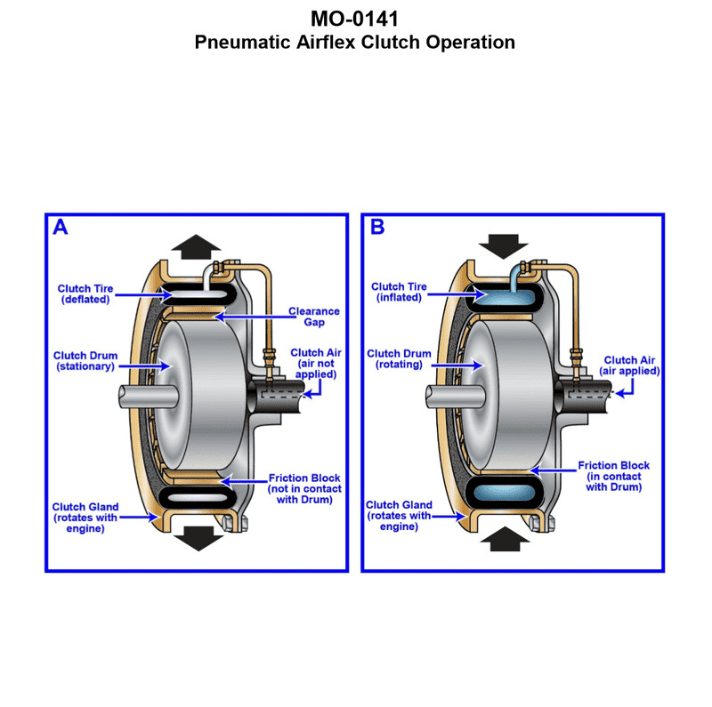
Question: The fishing industry factory ship to which you are assigned is fitted with main propulsion engines driving through pneumatic airflex clutches as shown in the illustration. What statement is true concerning this type of clutch? Illustration MO-0141
A. The clutch is an expanding type clutch and expands to engage against the clutch gland when inflated.
B. The clutch is an expanding type clutch and expands to engage against the clutch drum when inflated.
C. The clutch is a constricting type clutch and constricts to engage against the clutch drum when inflated.
D. The clutch is a constricting type clutch and constricts to engage against the clutch gland when inflated.
The Correct Answer is C **Explanation for Option C (Correct Answer):** Pneumatic Airflex clutches (often manufactured by companies like Eaton, Fawick, or their successors) used in marine propulsion systems for large vessels are typically of the drum type. In this configuration, the clutch mechanism consists of a flexible, toroidal rubber tube (the air bladder or tire) mounted externally to the driving or driven shaft component. When this tube is inflated with compressed air, it **constricts** (squeezes inwards) to grip the outer surface of a surrounding component, usually referred to as the **clutch drum** or friction rim. This action creates the friction necessary to transmit torque, thus engaging the clutch. Therefore, the clutch is a constricting type engaging the clutch drum when inflated. **Why the Other Options are Incorrect:** * **A) The clutch is an expanding type clutch and expands to engage against the clutch gland when inflated.** This is incorrect. While there are expanding pneumatic clutches (where the tube expands outwards to engage an inner drum surface), the standard, highly robust Airflex CB/VC/Wichita type clutches commonly used in marine propulsion applications are constricting. Furthermore, the term "clutch gland" is generally associated with seals and stuffing boxes, not the friction surface of the drum. * **B) The clutch is an expanding type clutch and expands to engage against the clutch drum when inflated.** This is incorrect because, as discussed, the widely used high-torque pneumatic clutches in marine propulsion (especially those described as "Airflex") are typically designed to constrict (squeeze inwards) onto the drum, not expand outwards. * **D) The clutch is a constricting type clutch and constricts to engage against the clutch gland when inflated.** This is incorrect. While the clutch is a constricting type, it engages the friction surface, which is the **clutch drum** (or friction rim), not the "clutch gland."

Question 23
Question: What is the drive arrangement of refrigeration compressor shown in figure "B" of the illustration? Illustration RA-0041
A. open
B. welded, fully hermetic
C. external drive
D. serviceable, bolted, accessible semi-hermetic
The Correct Answer is B **Explanation for Option B (welded, fully hermetic):** Option B is correct because Figure B in illustration RA-0041 typically depicts a modern, small-to-medium capacity refrigeration compressor used in domestic refrigerators, freezers, and small commercial applications. This type of compressor is characterized by: 1. **Welded Casing:** The motor and compressor mechanisms are sealed inside a steel shell that is permanently welded shut. This design prevents refrigerant leakage. 2. **Fully Hermetic:** Since the casing is welded and cannot be opened for repair (it must be replaced if it fails), it is classified as "fully hermetic." The drive motor and compressor are permanently sealed together within the refrigerant atmosphere. **Why the Other Options are Incorrect:** * **A) open:** "Open drive" compressors (or simply "open" compressors) have the motor separate from the compressor body, connected by a shaft that passes through a seal (often involving a belt or coupling). Figure B shows a single, sealed unit, not an open drive arrangement. * **C) external drive:** While technically the electrical power is external, "external drive" specifically refers to the mechanical drive mechanism being outside the compressor casing, usually seen in open-drive systems. Figure B shows an internal, integrated motor (hermetic design). * **D) serviceable, bolted, accessible semi-hermetic:** A semi-hermetic compressor (or serviceable hermetic) has a bolted casing (usually with access panels or heads) that allows technicians to open and service the internal motor and compressor components. Figure B clearly shows a smooth, welded shell, which is not designed for servicing.
Question 24
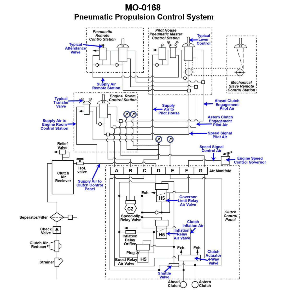
Question: The mollusc dredger to which you are assigned has a pneumatic propulsion control system as shown in the illustration. What statement is true concerning transfer of control? Illustration MO-0168
A. The transfer valve at the engine room control station is used to transfer control of propulsion from the engine room control station to the pilot house pneumatic master control station or vice versa.
B. The transfer valve at the pilot house pneumatic master control station is used to transfer control of propulsion from the pilot house master control station to the mechanical slave remote control station or vice versa.
C. The transfer valve at the pilot house pneumatic master control station is used to transfer control of propulsion from the pilot house master control station to the engine room control station or vice versa.
D. The transfer valve at the pneumatic remote-control station is used to transfer control of propulsion from the pneumatic remote-control station to the mechanical slave remote control station or vice versa.
The Correct Answer is A ### Explanation of Why Option A is Correct: In typical marine propulsion control systems, especially those using pneumatic remote control (like the one described for the mollusc dredger), the main transfer of control authority is handled at the **engine room** control station. The engine room (or local control station) generally holds the ultimate local control and is the point where the operator determines whether the engine is controlled locally (at the engine room control station) or remotely (usually the pilot house/bridge). Therefore, the transfer valve located at the engine room station is the mechanism used to shift control priority between the **Engine Room Control Station** (local/emergency) and the **Pilot House Pneumatic Master Control Station** (remote operating station). ### Explanation of Why Other Options Are Incorrect: **B) The transfer valve at the pilot house pneumatic master control station is used to transfer control of propulsion from the pilot house master control station to the mechanical slave remote control station or vice versa.** * **Incorrect:** The pilot house station is usually the primary remote control point (the master). It does not typically house a valve to transfer control to a "mechanical slave remote control station." Control transfer is almost universally managed between the *local* (engine room) and the *remote master* (pilot house). **C) The transfer valve at the pilot house pneumatic master control station is used to transfer control of propulsion from the pilot house master control station to the engine room control station or vice versa.** * **Incorrect:** While this describes the correct control points involved in the transfer (Pilot House $\leftrightarrow$ Engine Room), the physical transfer valve used to switch control authority is almost always located and operated at the **Engine Room Control Station**, not the Pilot House Master Control Station. **D) The transfer valve at the pneumatic remote-control station is used to transfer control of propulsion from the pneumatic remote-control station to the mechanical slave remote control station or vice versa.** * **Incorrect:** This option describes a transfer between two types of remote stations (pneumatic and mechanical slave). This configuration is highly atypical. The fundamental control transfer involves moving authority between the local control (Engine Room) and the main remote control (Pilot House/Bridge).

Question 25
Question: The fishing industry factory ship to which you are assigned has a pneumatic propulsion control system as shown in the illustration. Which control valve is responsible for bypassing the inflation delay orifice to insure rapid and positive reversals and to protect the clutches from excessive slip? Illustration MO-0167
A. H5 inflation air relay valve
B. C2 speed-slip relay valve
C. H5 boost relay air valve
D. H5 governor limit relay air valve
The Correct Answer is C The **H5 boost relay air valve** (Option C) is the component specifically designed to bypass the normal restriction (inflation delay orifice) during rapid maneuvers, such as reversing the direction of the propeller. The primary function of the delay orifice is to slow down the inflation of the pneumatic clutch to allow for smooth engagement under normal operating conditions. However, during rapid reversals, this slow engagement would cause excessive clutch slip, leading to overheating, wear, and potential failure. The H5 boost relay valve senses the demand for rapid change (often triggered by high pressure from the propulsion control system) and momentarily supplies high-volume, unrestricted air ("boost") to quickly and positively engage the clutch, minimizing slip and protecting the clutch components. **Why the other options are incorrect:** * **A) H5 inflation air relay valve:** While the H5 inflation relay valve controls the primary flow of air into the clutch, it generally operates in conjunction with the delay orifice to ensure smooth, slow engagement during normal acceleration or standard maneuvering. It is not the specific valve responsible for the *bypassing* or "boost" function during rapid reversals. * **B) C2 speed-slip relay valve:** The C2 speed-slip relay valve is typically involved in monitoring the rotational speeds of the input and output shafts (or propeller shaft) and adjusting the clutch pressure to minimize sustained slip under normal load conditions, often to protect the clutch from overheating, but it is not the valve that provides the rapid pressure boost for immediate engagement during reversals. * **D) H5 governor limit relay air valve:** The H5 governor limit relay valve is usually involved in limiting the maximum speed or power output of the engine or propulsion system under certain conditions (e.g., preventing overspeed or limiting torque). It does not function as the specific bypass valve for quick clutch engagement during reversals.
Question 26
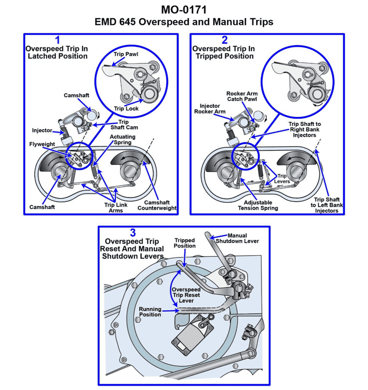
Question: The main engines on your fishing industry line vessel are equipped with manual shutdown levers as shown in the illustration. What statement concerning manual shutdown is true? Illustration MO-0171
A. The manual shutdown lever is operated by means of a remote pull cable and uses the governor fuel control linkage to accomplish engine shutdown.
B. The manual shutdown lever is operated by means of the emergency trip reset lever and uses the governor fuel control linkage.
C. The manual shutdown lever is operated by means of the over speed trip reset lever and uses the over speed trip mechanism to accomplish engine shutdown.
D. The manual shutdown lever is operated by means of a remote pull cable and uses the over speed trip mechanism to accomplish engine shutdown.
The Correct Answer is D **Explanation for Option D (Correct):** Manual shutdown systems designed for emergency use on large marine diesel engines (like those found on fishing industry line vessels) typically utilize a robust and immediate mechanism. This mechanism is usually the **over speed trip mechanism**. Activating this mechanism, even manually via a lever, forces the engine to shut down instantly by cutting off fuel supply, independent of the normal governor control. The lever itself is often connected to an easily accessible **remote pull cable** (or push rod) located away from the hot engine, making it suitable for emergency stops from a safe distance or remote station. **Explanation of Incorrect Options:** * **A) The manual shutdown lever is operated by means of a remote pull cable and uses the governor fuel control linkage to accomplish engine shutdown.** While a remote pull cable is common, using only the standard governor fuel control linkage for an *emergency* shutdown is generally incorrect. The governor linkage is designed for speed control; emergency systems prioritize immediate, forceful fuel cutoff, which is better achieved by triggering the dedicated trip mechanism. * **B) The manual shutdown lever is operated by means of the emergency trip reset lever and uses the governor fuel control linkage.** This is incorrect for two reasons: 1) The shutdown lever *activates* the trip, it does not use the *reset* lever. 2) As noted above, the emergency shutdown uses the trip mechanism, not the standard governor linkage, for execution. * **C) The manual shutdown lever is operated by means of the over speed trip reset lever and uses the over speed trip mechanism to accomplish engine shutdown.** The purpose of the manual shutdown lever is to *activate* the trip mechanism to stop the engine. The trip **reset** lever is used to prepare the engine for starting *after* a trip has occurred. Therefore, operating the shutdown lever via the reset mechanism is mechanically backward and incorrect.

Question 26
Question: Which of the following statements is true? Illustration RA-0012
A. Valve "14" is the king solenoid, valves "28" and "36" are both freeze box solenoids.
B. Valve "14" is the king solenoid, valves "28" and "36" are both chill box solenoids.
C. Valve "14" is the king solenoid, valve "28" is the chill box solenoid, and valve "36" is the freeze box solenoid.
D. Valve "14" is the king solenoid, valve "36" is the chill box solenoid, and valve "28" is the freeze box solenoid.
The Correct Answer is C ### 2. Explanation for Option C (Correct Answer) Option C is correct because it accurately identifies the standard nomenclature and function of the solenoids in the refrigeration system typically depicted in illustrations like RA-0012 (which represents a standard dual-temperature zone reefer system, often found in transport refrigeration). * **Valve "14" (King Solenoid):** Valve "14" is universally identified as the King Solenoid (or Main Solenoid/Suction Modulation Valve) in these diagrams. Its primary function is to control the overall flow of refrigerant to the entire unit, acting as the main shut-off valve for the suction side. * **Valve "28" (Chill Box Solenoid):** Valve "28" controls the flow of refrigerant specifically to the chill compartment (the zone requiring cooling but not freezing, typically the warmer zone). The chill box solenoid is often positioned before the freeze box solenoid in the circuit controlling the primary compartment. * **Valve "36" (Freeze Box Solenoid):** Valve "36" controls the flow of refrigerant specifically to the freeze compartment (the zone requiring deep cooling/freezing, typically the colder zone). This arrangement allows the system to independently modulate the temperature in the two distinct cargo zones (chill and freeze). ### 3. Explanation of Incorrect Options **A) Valve "14" is the king solenoid, valves "28" and "36" are both freeze box solenoids.** * **Incorrect:** While Valve "14" is correctly identified as the King Solenoid, valves "28" and "36" cannot both be freeze box solenoids in a standard dual-zone system. They must control separate zones (chill and freeze). **B) Valve "14" is the king solenoid, valves "28" and "36" are both chill box solenoids.** * **Incorrect:** Similar to Option A, while Valve "14" is correct, "28" and "36" cannot both be chill box solenoids. This would negate the system's ability to maintain a deep freeze temperature in the secondary compartment. **D) Valve "14" is the king solenoid, valve "36" is the chill box solenoid, and valve "28" is the freeze box solenoid.** * **Incorrect:** This option misidentifies the roles of "28" and "36" relative to the standard layout. Although the precise numbering varies slightly, in the typical configuration represented by RA-0012, Valve "28" is dedicated to the Chill Box, and Valve "36" is dedicated to the Freeze Box. This option swaps the functions of the two zone solenoids.
Question 27
Question: The main engines on your uninspected fishing trawler are equipped with over speed trip devices as shown in the illustration. What statement concerning the operation of the over speed trip is true? Illustration MO-0171
A. The over speed trip senses centrifugal force proportional to engine speed and limits the engine speed to the rated speed, while allowing the engine to continue to run at the rated speed.
B. The over speed trip senses oil pressure proportional to engine speed and limits the engine speed to the rated speed, while allowing the engine to continue to run at the rated speed.
C. The over speed trip senses centrifugal force proportional to engine speed and shuts the engine down at a pre-determined, specified maximum speed setting.
D. The over speed trip senses oil pressure proportional to engine speed and shuts the engine down at a pre- determined, specified maximum speed setting.
The Correct Answer is C **Explanation of Correct Option (C):** The primary function of an over speed trip (or governor over speed device) on a main engine is safety, specifically to prevent catastrophic engine failure due to excessive RPM. Historically and commonly, mechanical over speed trips utilize a weighted mechanism (often a flyball or plunger) that senses **centrifugal force**. As the engine speed increases, the centrifugal force acting on the weights increases proportionally. When the engine RPM reaches a pre-determined, dangerous maximum speed setting (typically 15% above rated speed), the centrifugal force overcomes the resistance (usually a spring), causing the weights to move outward. This movement mechanically or hydraulically triggers a shut-down mechanism (like closing the fuel racks or cutting ignition), thereby **shutting the engine down** completely and immediately to prevent damage. **Why Other Options Are Incorrect:** * **A) Incorrect:** This option correctly identifies that the trip senses centrifugal force proportional to speed, but incorrectly describes its function. An over speed trip is a safety shutdown device, not a speed limiting or regulating device that allows the engine to continue running at the rated speed. Speed limiting and regulation is the job of the normal operating governor. * **B) Incorrect:** This option incorrectly states the sensing mechanism is oil pressure proportional to speed. While some engine speed governors or monitoring systems utilize oil pressure for certain functions, the traditional, dedicated over speed trip mechanism primarily relies on direct mechanical (centrifugal) sensing for reliability. Furthermore, like option A, it incorrectly states the trip limits speed while allowing the engine to continue running. * **D) Incorrect:** While this option correctly identifies the outcome (shuts the engine down at a pre-determined maximum speed), it incorrectly states that the primary sensing mechanism for a dedicated mechanical over speed trip is oil pressure proportional to engine speed. The standard mechanism is centrifugal force.
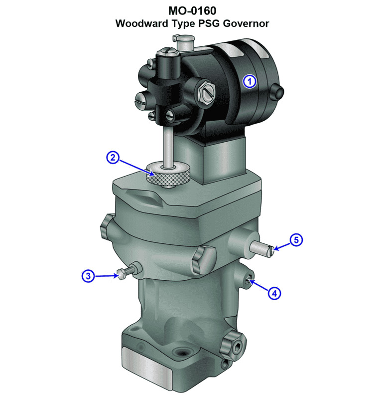
Question 28
Question: The diesel generators on your uninspected fishing trawler are fitted with speed control governors of the type shown in the illustration. If an adjustment is made to item #2, what will change? Illustration MO-0160
A. The speed droop setting
B. The governed speed setting
C. The minimum low speed setting
D. The maximum high speed setting
The Correct Answer is B. **Explanation for Option B (The governed speed setting) being correct:** Item \#2 in a mechanical speed control governor (often depicted as a knurled knob or adjustment screw connected to the spring tension mechanism) is typically the **speed setting adjustment** (or manual speed changer). By adjusting item \#2, the tension on the main speeder spring (which counteracts the centrifugal force of the flyweights) is changed. Increasing the spring tension requires the engine to run faster (higher RPM) to generate enough centrifugal force to overcome that tension and move the fuel rack to maintain the set speed. Decreasing the tension lowers the required speed. Therefore, adjusting item \#2 directly changes the **governed speed setting** (the desired speed at which the governor maintains the engine operation). **Explanation for why the other options are incorrect:** * **A) The speed droop setting:** Speed droop determines how much the engine speed decreases as the load increases. This adjustment is usually controlled by a separate mechanism (often a linkage pivot point adjustment) that modifies the mechanical leverage ratio between the governor output and the fuel rack/throttle, not the main speed setting knob (item \#2). * **C) The minimum low speed setting:** The minimum low speed (idle speed) is typically controlled by a separate mechanical stop or adjustment that limits the travel of the fuel rack/throttle at the minimum speed position. While related to engine operation, it is not the function of the main speed setting adjustment used during normal governing operation. * **D) The maximum high speed setting:** While the governed speed could be set to the engine's maximum safe speed limit, the maximum mechanical limit of the governor's action is usually determined by internal physical stops or a separate high-limit stop adjustment. Item \#2 adjusts the **operating speed within the governor's range**, not the fixed, physical maximum design limit of the engine or the governor mechanism itself.
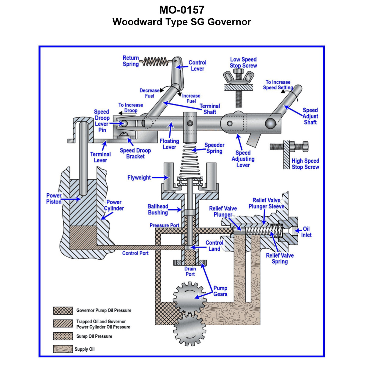
Question 29
Question: The deck winch on your ship-handling tug is fitted with a Woodward SG Type governor, as shown in the illustration. In addition to variable governed speed setting, what other group of settings is built into this particular governor? Illustration MO-0157
A. Engine idle speed (minimum governed speed), engine speed limit (maximum governed speed)
B. Engine idle speed (minimum governed speed), engine load limit (maximum fuel delivery)
C. Engine load limit (maximum fuel delivery), engine speed limit (maximum governed speed)
D. Engine speed droop (load sharing adjustment), governor compensation (stability adjustment)
The Correct Answer is A ### 1. Explanation for Option A (Correct) The Woodward SG (Standard Governor) type is a **mechanical-hydraulic governor** often used for speed control on various engine applications, including winches on tugboats. While it fundamentally provides variable speed governing (the primary function), it typically incorporates adjustments that define the operating limits of the engine under governor control: * **Engine idle speed (minimum governed speed):** This sets the lowest stable speed the governor will maintain when the speed lever is at its minimum setting. This is essential for engine operation, especially during periods of no load or standby. * **Engine speed limit (maximum governed speed):** This sets the highest speed the governor will allow the engine to reach, regardless of the position of the speed lever (unless the speed lever is moved to an underspeed setting). This acts as an overspeed protection limit (though often a separate overspeed trip is used for emergency cutoff, the maximum speed stop is a key governor setting). These two settings (minimum and maximum speed stops/settings) are basic and standard adjustments built into the mechanical linkage or structure of the SG governor to define the operational range available to the operator, in addition to the operator-controlled speed setting (variable governed speed). ### 2. Explanation of Why Other Options Are Incorrect **B) Engine idle speed (minimum governed speed), engine load limit (maximum fuel delivery)** * While engine idle speed is correct, the **engine load limit (maximum fuel delivery)** is typically a separate mechanical stop (often called the "maximum fuel rack stop" or "torque limit") built into the engine's fuel pump linkage, *not* a primary adjustment of the standard SG governor head itself. Although the governor controls fuel delivery based on speed, defining the absolute physical maximum fuel rack position is usually an engine/pump setting, not an SG governor adjustment. **C) Engine load limit (maximum fuel delivery), engine speed limit (maximum governed speed)** * Maximum governed speed is correct. * Engine load limit (maximum fuel delivery) is incorrect for the reason stated above—it's usually an engine fuel system setting, not a primary built-in adjustment of the governor head linkage (like the min/max speed settings are). **D) Engine speed droop (load sharing adjustment), governor compensation (stability adjustment)** * While droop and compensation are critical adjustments on *all* hydraulic governors (including the SG) for stability and load sharing, they define the *quality* of the speed control (stability and responsiveness), not the *range* or *limits* of engine operation. * The question asks what *other group of settings* is built in besides the variable speed setting. Minimum and maximum speed stops define the fundamental operational limits required for the engine, whereas droop and compensation are fine-tuning adjustments for the dynamics of governing. The most fundamental physical limits built into the SG governor's structure are the minimum and maximum speed settings (Option A).
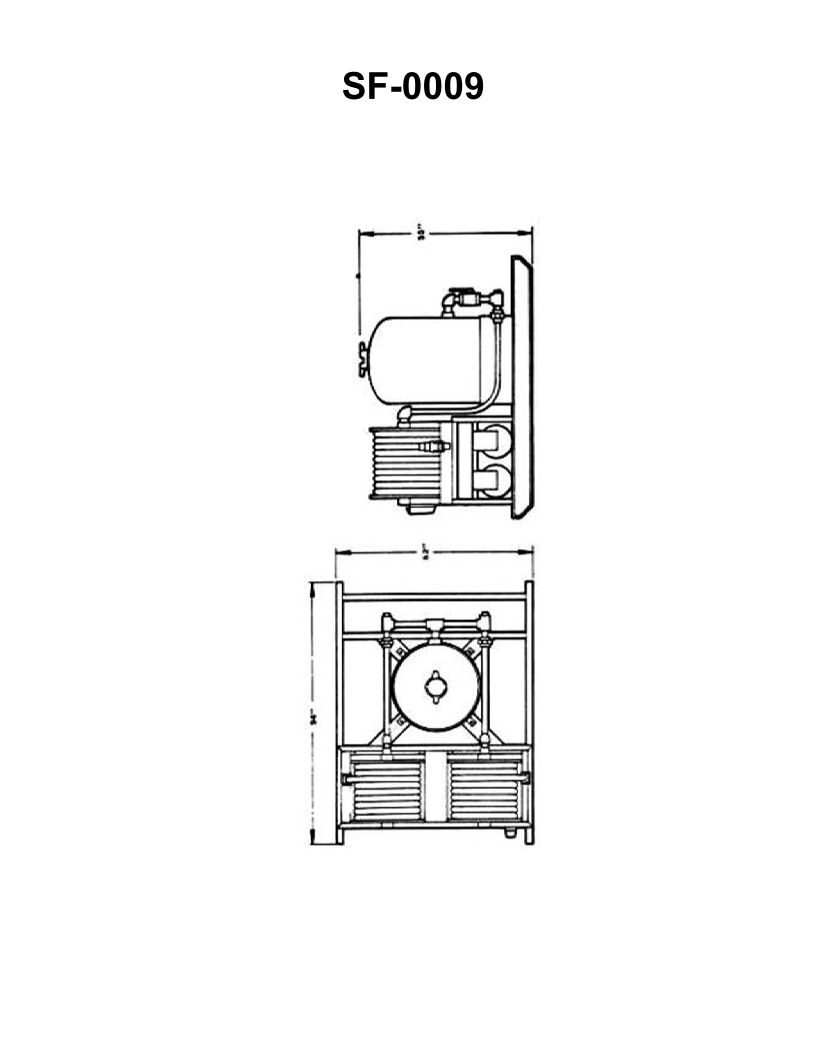
Question 32
Question: The fire extinguishing equipment shown in the illustration is a large __________. Illustration SF-0009
A. dry chemical hose reel system
B. CO2 hose reel system
C. Halon 1301 hose reel system
D. light water hose reel system
The Correct Answer is A. **Explanation for Option A (dry chemical hose reel system):** The illustration SF-0009 depicts large, permanently installed firefighting equipment, typically found in industrial facilities, aircraft hangars, or chemical plants. A "dry chemical hose reel system" uses finely powdered chemical agents (such as monoammonium phosphate or sodium bicarbonate) expelled under pressure, making it highly effective for extinguishing Class B (flammable liquids) and Class C (electrical) fires, and often Class A fires as well. When referring to a "large" piece of fire extinguishing equipment deployed via a long hose and nozzle assembly on a reel, the description perfectly matches a high-capacity, fixed dry chemical system. **Explanation of Incorrect Options:** * **B) CO2 hose reel system:** While CO2 systems exist on reels, they are typically smaller or used in specific environments (like engine rooms or for sensitive equipment). A large industrial system relying on a long hose and high discharge volume often utilizes dry chemical powder rather than the gaseous CO2 agent, especially when the illustration implies substantial reach and extinguishing capability against large-scale flammable liquid fires. * **C) Halon 1301 hose reel system:** Halon 1301 is a gas primarily used in total flooding systems (where the agent fills an entire enclosure, like server rooms) or small portable extinguishers. Due to environmental concerns and international restrictions (like the Montreal Protocol), its use in new, large, manual discharge hose reel systems is extremely rare or banned entirely. * **D) light water hose reel system:** "Light water" (AFFF or FFFP foam solutions mixed with water) systems are commonly used for large flammable liquid fires. While they are deployed via reels, the term "large" equipment often defaults to the highly versatile and high-volume dry chemical system in contexts where a general classification of a large industrial hose reel system is required, unless the illustration specifically showed foam generation equipment. In standard firefighting nomenclature for generic industrial reels, dry chemical (A) is often the intended correct answer for a large industrial apparatus that is not water or standard foam.

Question 34
Question: If the needle and seat assembly is excessively eroded, the valve cage assembly can be replaced. In replacing the original valve cage assembly rated at 1/2 tons, what would be the result if the replacement valve cage was oversized at 5 tons? Illustration RA-0007
A. The expansion valve would function normally, with the presentation of no problems.
B. The evaporator would be overfed producing consistently insufficient superheat.
C. The evaporator would be starved producing consistently excessive superheat.
D. The expansion valve would hunt excessively, alternately starving and overfeeding the evaporator coil.
The Correct Answer is D. ### Why Option D is Correct The valve cage assembly (which contains the needle and seat) dictates the maximum flow capacity of the thermostatic expansion valve (TXV). The original valve was rated for a system capacity of $1/2$ ton. The replacement valve cage is significantly oversized at $5$ tons, meaning its flow area is ten times larger than necessary. When a TXV is grossly oversized, even a minute movement of the needle off the seat results in a massive change in refrigerant flow (high flow gain). 1. **Initial Overfeeding:** The TXV bulb senses warm vapor leaving the evaporator and opens slightly. Due to the oversized cage, this small opening immediately dumps a huge quantity of liquid refrigerant into the evaporator (overfeeding). 2. **Insufficent Superheat & Closure:** This rapid overfeeding causes the suction line temperature to drop sharply (low or zero superheat). The TXV bulb senses this cold temperature and responds by closing the valve quickly. 3. **Starving & Opening:** Since the valve is now closed (or nearly closed), the refrigerant flow stops or is severely restricted, causing the evaporator to quickly run out of liquid and the superheat to rise excessively. 4. **The Cycle Repeats (Hunting):** The TXV bulb senses the excessive superheat and opens the valve again, leading back to step 1. This continuous cycle of alternating between massive overfeeding (low superheat) and severe starving (high superheat) is known as **excessive hunting**. ### Why Other Options Are Incorrect **A) The expansion valve would function normally, with the presentation of no problems.** This is incorrect. Grossly oversizing a metering device (like an expansion valve) fundamentally changes its control characteristics, leading directly to instability (hunting). **B) The evaporator would be overfed producing consistently insufficient superheat.** This is incorrect because while the valve will initially overfeed, the TXV's control mechanism will respond to the low superheat by closing the valve, leading to a period of starving. The result is not consistent overfeeding, but alternating extremes (hunting). **C) The evaporator would be starved producing consistently excessive superheat.** This is incorrect for the same reason as B. While the valve will eventually starve the coil after a period of closure, the control mechanism will respond to the high superheat by opening the valve, leading to a period of overfeeding. The system does not settle on a consistent state of starving.
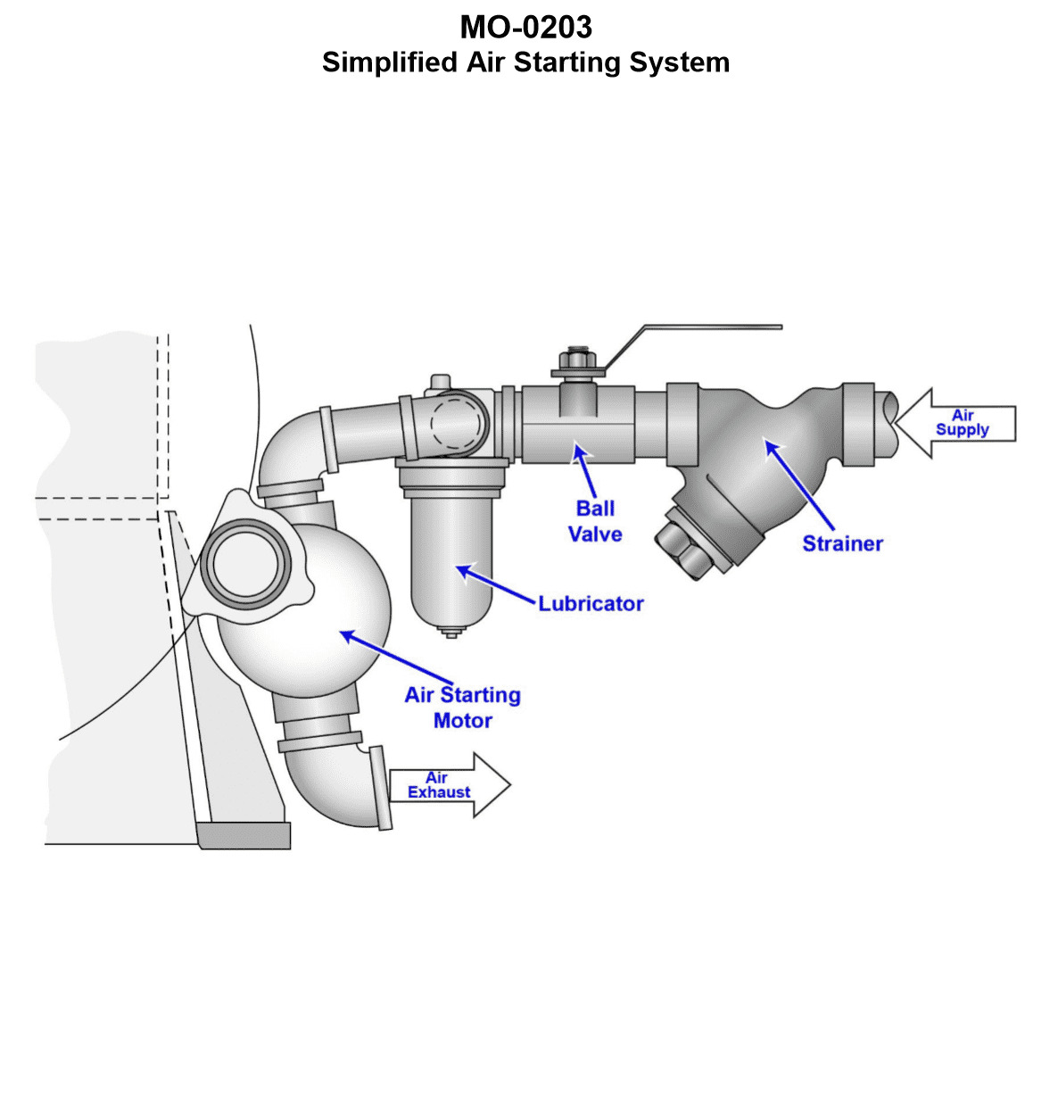
Question 36
Question: The main engines on your fishery research vessel utilize a starting system similar to that shown in the illustration. The air supply pressure and engine room ambient temperatures are both within the normal range. Upon attempted start-up, the engine turns very slowly, and the flow rate of air from the air starting motor exhaust is very low. Which of the listed conditions would most likely be the cause of the failure to start? Illustration MO-0203
A. The in-line strainer basket element is severely restricted.
B. The air-starting motor vanes are stuck in their slots.
C. The in-line lubricator siphon tube is severely restricted.
D. The fuel injection system piping is air-bound.
The Correct Answer is A **Why option A is correct:** The symptoms described—the engine turning very slowly and the extremely low flow rate of air from the air starting motor exhaust—indicate a severe lack of airflow *into* the starting motor. The air supply pressure is noted as normal, meaning the restriction must occur between the main air supply and the starting motor itself. An in-line strainer (filter) is designed to remove contaminants from the air before it reaches the motor. If the strainer basket element becomes severely restricted or clogged, it drastically reduces the volume of high-pressure air reaching the motor. This reduction in air volume directly leads to insufficient torque (slow turning) and minimal exhaust flow, perfectly matching the observed failure symptoms. **Why option B is incorrect:** If the air-starting motor vanes were stuck in their slots, the motor would likely bind up entirely, potentially turning very briefly or not at all, rather than turning "very slowly." More importantly, even if the vanes were stuck, the air pressure would still be applied to the motor housing, and the flow of air (volume) would likely remain high or even increase (as the air attempts to bypass the blocked vanes or rotor), which contradicts the symptom of a very low exhaust air flow rate. The primary failure is a lack of *input flow*, not an internal motor mechanical fault. **Why option C is incorrect:** The in-line lubricator’s function is to inject oil mist into the starting air for lubrication. A restricted siphon tube would inhibit or stop oil delivery, leading to premature wear and eventually slow operation or failure due to friction. However, a restriction in the siphon tube (which handles the oil) does not restrict the main air path volume through the starter system itself. Therefore, it would not cause the immediate and drastic reduction in air flow rate observed at the exhaust. **Why option D is incorrect:** The fuel injection system being air-bound prevents fuel from being injected into the cylinders. This condition would cause the engine to crank normally (since the air starter is working), but the engine would fail to fire or start running under its own power. It would not, however, affect the mechanical operation of the air starter itself, which means the engine turning speed and the air starter exhaust flow rate would both remain normal (assuming sufficient air pressure).
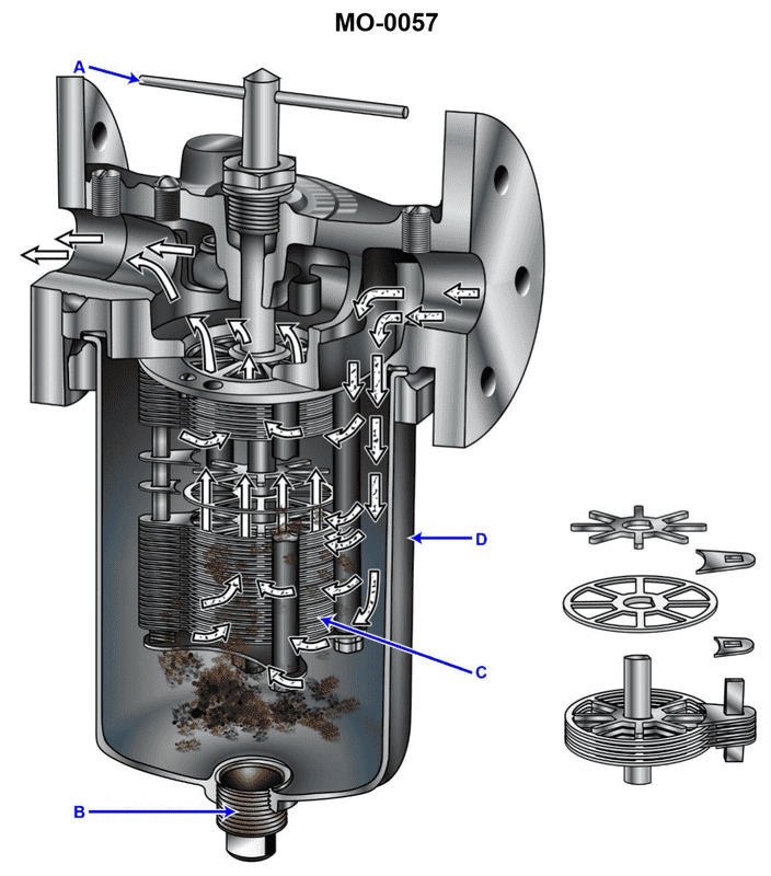
Question 38
Question: A diesel generator set on your fishing trawler has a simplex lube oil strainer of the type shown in the illustration, situated on the discharge side of the lube oil pump. At a specified engine rpm and lube oil temperature, you notice that the pressure drop becomes unacceptably high. When you rotate the cleaning handle you notice that it is extremely difficult to rotate. What should be done? Illustration MO-0057
A. No special consideration need be taken as long as the cleaning handle (A) rotates, even if it rotates with great difficulty.
B. After stopping the engine, the strainer element should be withdrawn and soaked in solvent to break up the heavy deposits on the disk stack (C).
C. The cleaning handle (A) should be forced to rotate, even if it requires an extender handle to produce greater rotating torque.
D. After stopping the engine, the drain plug (B) should be removed to drain the accumulated sludge from the strainer sump.
The Correct Answer is B **Explanation for Option B (Correct):** Option B is correct because the described symptoms indicate a severe fouling condition that manual rotation is failing to resolve. An unacceptably high pressure drop across the strainer at normal operating conditions means the flow passages are significantly restricted. The extreme difficulty in rotating the cleaning handle (A) indicates that the accumulated contaminants (sludge, carbon, and debris) on the disk stack (C) are packed so tightly or have hardened, binding the element and preventing the scraper blades from effectively cleaning the filter disks. When this condition occurs, simply rotating the handle is insufficient. The engine must be stopped to prevent damage due to lack of lubrication (caused by the excessive pressure drop), and the strainer element must be manually removed and cleaned, typically by soaking it in a suitable solvent (like diesel fuel or a specialized cleaning agent) to dissolve or loosen the heavy, hardened deposits before thorough rinsing and reinstallation. **Why the other options are incorrect:** * **A) No special consideration need be taken as long as the cleaning handle (A) rotates, even if it rotates with great difficulty.** This is incorrect. The difficulty in rotation, combined with the unacceptably high pressure drop, signals a dangerous condition (severe fouling) that is impeding oil flow. Ignoring this issue risks engine damage due to inadequate lubrication or bearing failure. * **C) The cleaning handle (A) should be forced to rotate, even if it requires an extender handle to produce greater rotating torque.** This is highly dangerous and incorrect practice. Forcing the rotation risks bending or breaking the internal mechanism (such as the cleaning blades or the disk stack itself) or stripping the mechanism that turns the stack. This would cause catastrophic failure of the strainer and potentially introduce metal debris into the lube oil system, leading to severe engine damage. * **D) After stopping the engine, the drain plug (B) should be removed to drain the accumulated sludge from the strainer sump.** While draining the sump (B) is a necessary step during routine maintenance to remove accumulated heavy sludge, it addresses only the contaminants that have already dropped out of the flow stream into the bottom of the casing. It will not clear the hardened, bound deposits tightly adhering to the strainer disk stack (C) which are causing the high pressure drop and the difficulty in rotation. The core issue requires cleaning the element itself.
Question 39
Question: A diesel generator set on your fishing industry factory ship has a simplex lube oil strainer of the type shown in the illustration, situated on the discharge side of the lube oil pump. At a specified engine rpm and lube oil temperature, you notice that the inlet pressure is increasing and the outlet pressure is decreasing, resulting in an unacceptable pressure drop. What should be done? Illustration MO-0057
A. While the engine is running, the drain plug (B) should be carefully loosened to drain the sludge from the strainer sump.
B. While the engine is running, the cleaning handle (A) should be rotated one or more full turns to remove the accumulated dirt from the disk stack (C).
C. While the engine is running, the cleaning handle (A) should be rotated one-half turn to remove the accumulated dirt from the disk stack (C).
D. The drain plug (B) is removed to drain the sludge from the strainer sump, but the engine must be stopped to perform this operation.
The Correct Answer is B **Explanation of Correct Option (B):** Option B is correct because the described symptoms—increasing inlet pressure and decreasing outlet pressure, leading to an unacceptable pressure drop across the strainer—indicate that the filter element (disk stack C) is clogged with particulate matter. The illustration MO-0057 typically represents a simplex back-flushing or edge-type strainer (often an Auto-Klean type) designed for continuous self-cleaning while the system is operational. The cleaning handle (A) is mechanically linked to the disk stack (C) and rotating it scrapes the accumulated dirt (sludge/particles) off the surface of the disks. This dislodged dirt falls into the sump below, immediately restoring the flow path and reducing the pressure drop. For effective cleaning and to ensure all accumulated dirt is removed, the handle should be rotated one or more full turns, as specified in standard operating procedures for this type of strainer. This procedure is specifically designed to be performed while the engine (and thus the lube oil pump) is running. **Why the Other Options are Incorrect:** * **A) While the engine is running, the drain plug (B) should be carefully loosened to drain the sludge from the strainer sump.** This is incorrect for two reasons. First, loosening the drain plug (B) while the system is under pressure would cause a catastrophic and dangerous loss of lube oil, potentially starving the engine. Second, while the sump does contain sludge, draining the sump alone does not address the primary problem, which is the clogged filtering element (C) causing the pressure drop. The element must first be cleaned (rotated via A) to dislodge the clogging material. * **C) While the engine is running, the cleaning handle (A) should be rotated one-half turn to remove the accumulated dirt from the disk stack (C).** While rotating the handle (A) is the correct action, one-half turn is typically insufficient to ensure the entire surface of the disk stack (C) has been scraped clean. Standard practice for these continuous-cleaning strainers requires one or more complete revolutions to ensure full coverage and effective removal of the accumulated debris. * **D) The drain plug (B) is removed to drain the sludge from the strainer sump, but the engine must be stopped to perform this operation.** Stopping the engine and removing the drain plug (B) would be the correct procedure for draining the sump sludge (after the filter element has been cleaned), but it is not the immediate or primary action required to resolve the unacceptable pressure drop caused by the *clogged element*. The element (C) is cleaned by rotating handle (A), and this action must be performed immediately while the engine is running to restore flow. Stopping the engine is not necessary for the immediate solution.

Question 39
Question: Using the device shown in the illustration, which of the following statements is true when adding refrigerant as a vapor to the low side of the refrigeration system? Illustration RA-0001
A. The hose labeled "K" should be connected to the suction service valve service port, the hose labeled "J" should be connected to the vapor valve on the refrigerant cylinder and the valve labeled "C" should be closed.
B. The hose labeled "H" should be connected to the suction service valve service port, the hose labeled "J" should be connected to the vapor valve on the refrigerant cylinder and the valve labeled "G" should be open.
C. The hose labeled "K" should be connected to the suction service valve service port, the hose labeled "J" should be connected to the vapor valve on the refrigerant cylinder and the valve labeled "C" should be open.
D. The hose labeled "H" should be connected to the suction service valve service port, the hose labeled "J" should be connected to the vapor valve on the refrigerant cylinder and the valve labeled "G" should be closed.
The Correct Answer is B **Explanation for Option B (Correct):** Option B describes the correct procedure for adding refrigerant vapor to the low-side (suction side) of a refrigeration system using a typical manifold gauge set. 1. **Hose H connected to the suction service valve service port:** Hose H is the blue hose, which is traditionally connected to the low-pressure side (suction line) of the system. This allows the technician to monitor the system's low-side pressure and introduce refrigerant into the low side. 2. **Hose J connected to the vapor valve on the refrigerant cylinder:** Hose J is the yellow (center) hose, which is used for recovery, charging, and vacuum operations. When charging, it is connected to the refrigerant source (the cylinder). Since the system is being charged with *vapor*, the cylinder should be upright (or connected to the vapor port if it has separate liquid/vapor ports). 3. **Valve G should be open:** Valve G is the low-side (blue) manual valve on the manifold gauge set. To allow the refrigerant vapor to flow from the cylinder (via hose J) through the manifold and into the system's low side (via hose H), the low-side valve (G) must be open. **Why the Other Options are Incorrect:** * **Option A is Incorrect:** * Hose K is the red hose, which is connected to the high-pressure side. Connecting the high-side hose (K) to the suction (low-side) service port is incorrect. * Valve C is the high-side (red) valve. Keeping the high-side valve (C) closed is necessary, but the connection points are wrong. * **Option C is Incorrect:** * Hose K is the high-side hose and should not be connected to the low-side port. * Valve C is the high-side valve. Opening the high-side valve (C) while charging through the center port (J) would allow the refrigerant to flow into the high side of the system, which is not the typical procedure for charging *vapor* into the low side, and it's generally dangerous unless the system is off or specialized procedures are being followed. * **Option D is Incorrect:** * While the connections (H to low side, J to cylinder) are correct, valve G (the low-side valve) must be **open** to allow the refrigerant to flow into the low side of the system. If valve G is closed, the refrigerant cannot pass through the manifold and enter the system.

Question 43
Question: Concerning the arrangement of equipment and associated hoses shown in the illustration, which statement is true? Illustration RA-0059
A. When recovering refrigerant from the centrifugal chiller using this method, it is possible to achieve the recovery levels required by law without any further recovery.
B. When recovering refrigerant from the centrifugal chiller using this method, the entire charge may be removed in one procedure.
C. When recovering refrigerant from the centrifugal chiller using this method, the containment tank should be vented back to the chiller evaporator shell.
D. When recovering refrigerant from the centrifugal chiller using this method, the refrigerant is being recovered as a liquid.
The Correct Answer is A **Explanation for Option A (Correct):** Option A states: "When recovering refrigerant from the centrifugal chiller using this method, it is possible to achieve the recovery levels required by law without any further recovery." The illustration (RA-0059, which typically depicts a recovery method involving a recovery unit hooked up to a centrifugal chiller, possibly utilizing both liquid and vapor recovery lines) describes a procedure for deep evacuation and recovery of refrigerant from low-pressure appliances (like centrifugal chillers). Current EPA regulations (Section 608) require specific vacuum levels (e.g., 25 inches of Hg for appliances with a full charge of 35 lbs or more) or very low evacuation levels (e.g., 10 inches of Hg) before major repair or disposal. Standard recovery equipment designed for low-pressure systems, especially those utilizing water-cooled condensers or supplemental heat, are specifically designed to achieve and often exceed these required deep vacuum levels (15 inches Hg or better) in a single procedure to meet legal recovery mandates. **Explanation of Why Other Options are Incorrect:** * **B) When recovering refrigerant from the centrifugal chiller using this method, the entire charge may be removed in one procedure.** This is technically false. While the bulk of the charge is removed, low-pressure chillers inherently contain large amounts of refrigerant dissolved in the oil and trapped in the evaporator shell at low pressure. Achieving the required legal recovery levels often requires additional steps such as the "heater and pump out" method, or utilizing a high-efficiency recovery unit capable of deep vacuum, but even then, residual refrigerant remains, requiring the recovery unit to run until the required vacuum (e.g., 25 inches Hg) is reached. The procedure requires achieving a mandated vacuum level, not simply "removing the entire charge" easily in one procedure. * **C) When recovering refrigerant from the centrifugal chiller using this method, the containment tank should be vented back to the chiller evaporator shell.** This is highly incorrect and dangerous. Venting the recovery (containment) tank back to the chiller evaporator shell would reverse the recovery process and contaminate the chiller with potentially non-condensable gases from the recovery tank, and would certainly prevent achieving the deep vacuum required by law. The recovery tank is designed to capture the refrigerant, not recirculate vapor back to the chiller. * **D) When recovering refrigerant from the centrifugal chiller using this method, the refrigerant is being recovered as a liquid.** While liquid recovery is often the most efficient initial step to remove the bulk of the charge quickly, the overall procedure for deep recovery from a centrifugal chiller (especially to meet legal limits) always concludes with **vapor recovery** (pulling a vacuum) to remove the remaining refrigerant vapor and achieve the required deep vacuum level. Therefore, stating the refrigerant is *only* being recovered as a liquid is inaccurate regarding the entire legally compliant recovery procedure.
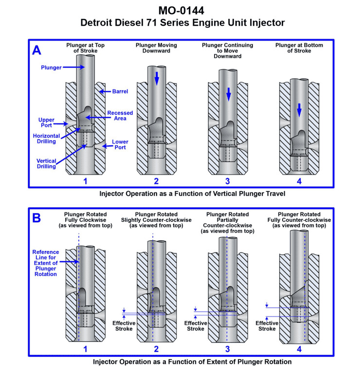
Question 45
Question: The uninspected fishing vessel to which you are assigned has a deck winch drive engine fitted with fuel injectors with the operating principle as shown in the illustration. In figure "A" which plunger travel position corresponds to when fuel injection ends? Illustration MO-0144
A. 1
B. 2
C. 3
D. 4
The Correct Answer is C. ### Explanation for Option C (3) The illustration (MO-0144, which depicts a common type of jerk pump fuel injection system) shows a fuel pump plunger that controls both the start and end of injection using a helix (or scroll) cut into its body, interacting with inlet/spill ports in the barrel. Position **3** corresponds to the end of fuel injection. This occurs when the upper edge of the helix/scroll aligns with and uncovers the spill port (or relief port). Once the spill port is uncovered, the high-pressure fuel trapped above the plunger rushes out through the port and returns to the suction gallery (or fuel tank). Because the pressure immediately drops to zero, the delivery valve closes, and injection into the engine cylinder ceases. ### Explanation for Incorrect Options * **A) 1:** Position 1 represents the plunger at or near the bottom of its stroke (Bottom Dead Center) or during the suction phase. Both the inlet and spill ports are open, allowing the fuel gallery to fill the space above the plunger. No injection is occurring. * **B) 2:** Position 2 represents the point where fuel injection begins. The plunger has moved upward, and its effective top edge has just covered both the inlet and spill ports (the "effective stroke" begins here). From this point until the spill port is uncovered by the helix, the fuel is pressurized and delivered to the injector. * **D) 4:** Position 4 represents the plunger near the top of its stroke (Top Dead Center) and well past the point where injection ended (position 3). The spill port has been uncovered for some time, and the pressure relief has occurred. This position merely signifies the end of the plunger's upward travel (or the end of the overall pump stroke).

Question 45
Question: When recovering the remaining R-134a refrigerant from the centrifugal chiller shown in the illustration as a vapor using the recovery unit's compressor, in addition to opening valves "1a", "1b", and the compressor suction and discharge isolation valves, which of the following would be the correct valve lineup? Illustration RA-0028
A. valves "2", "5", "7", "8", and "10" open; valves "3", "4", and "6" closed
B. valves "3", "4", and "6" open; valves "2", "5", "7", "8", and "10" closed
C. valves "3", "4", "7", "6" and "10" open; valves "2", "5", and "8" closed
D. valves "3", "5", and "6" open; valves "2", "4", "7", "8", and "10" closed
The Correct Answer is B ### 1. Explanation of Correct Option (B) The goal is to recover R-134a refrigerant as a **vapor** from the centrifugal chiller using the recovery unit's compressor, sending it to a recovery tank. This process requires a clear, isolated path for the refrigerant vapor to be drawn in, compressed, and discharged. Option B requires: **valves "3", "4", and "6" open; valves "2", "5", "7", "8", and "10" closed.** * **Valve 3 (Open):** This valve typically controls the main suction inlet line, allowing the low-pressure refrigerant vapor from the chiller (connected via 1a or 1b) to enter the recovery unit's suction manifold. This is essential for recovery. * **Valve 4 (Open):** This valve controls the discharge outlet line. The high-pressure compressed vapor exits the recovery unit through Valve 4, routing the refrigerant to the recovery tank. This is essential for recovery. * **Valve 6 (Open):** While the exact flow path depends on the specific illustration, Valve 6 is typically required to complete the necessary internal suction flow path, often routing the vapor through an internal filter, manifold, or heat exchanger before it reaches the compressor suction port. * **Valves 2, 5, 7, 8, and 10 (Closed):** These valves must be closed because they typically control bypass lines, liquid transfer ports (2, 5, 8), or non-condensable gas purge lines (7, 10). Keeping these valves closed ensures that the vapor flow is correctly directed through the compressor (3 -> Compressor -> 4) and prevents refrigerant loss, mixing with air, or bypassing the intended compression path. ### 2. Explanation of Incorrect Options **A) valves "2", "5", "7", "8", and "10" open; valves "3", "4", and "6" closed** * **Why it's wrong:** Valves 3 (Suction Inlet) and 4 (Discharge Outlet) are both closed. With the inlet and outlet closed, no refrigerant can be pulled from the chiller or discharged into the recovery tank, rendering the recovery unit inoperable. **C) valves "3", "4", "7", "6" and "10" open; valves "2", "5", and "8" closed** * **Why it's wrong:** Although the necessary paths (3, 4, 6) are open, this option incorrectly opens isolation/auxiliary valves 7 and 10. Valve 7 is often a purge or vent line, and 10 is often an auxiliary connection. Opening these isolation points during recovery is dangerous, as it can allow non-condensables (air) to enter the system or cause refrigerant to leak or divert away from the recovery tank. **D) valves "3", "5", and "6" open; valves "2", "4", "7", "8", and "10" closed** * **Why it's wrong:** Valve 3 (Suction Inlet) is open, allowing vapor to be drawn in, but Valve 4 (Discharge Outlet) is closed. If the compressor pulls refrigerant but has no open path to discharge it to the recovery tank, high pressures will build up, the recovery unit will quickly stall, or the pressure relief devices will activate.
Question 46
Question: The mollusc dredger to which you are assigned has a deck winch drive engine fitted with fuel injectors with the operating principle as shown in the illustration. In figure "A" which plunger travel position corresponds to when fuel injection begins? Illustration MO-0144
A. 1
B. 2
C. 3
D. 4
The Correct Answer is B. ### Explanation for Option B ("2"): Option B refers to position '2' in the illustration, which depicts a Fuel Injection Pump (FIP) barrel and plunger assembly. The operating principle shown is typically for a jerk-type pump, which regulates the amount of fuel delivered by varying the effective stroke of the plunger. * **Fuel Injection Begins:** Injection starts when the top edge of the plunger (the helix or scroll) first closes the inlet port (or spill port) on the pump barrel as the plunger moves upwards. In position **2**, the top edge of the plunger has just risen sufficiently to cover the inlet port. Once this port is covered, the fuel trapped above the plunger can no longer escape back to the fuel gallery. The pressure rapidly builds up due to the continuing upward movement of the plunger, opening the delivery valve and forcing fuel through the injector nozzle into the engine cylinder. Therefore, position 2 marks the start of the effective pumping stroke and the beginning of fuel injection. ### Explanation for Incorrect Options: * **Option A ("1"):** Position 1 shows the plunger at the lowest point of its stroke (Bottom Dead Center for the pump mechanism). Both the inlet port and the spill port are fully uncovered. Fuel is flowing freely into the space above the plunger (charging the pump). No pressure build-up or injection is possible here. * **Option C ("3"):** Position 3 shows the plunger further along its upward stroke. Injection is well underway, as the top edge is far above the inlet port. At this point, the effective pumping stroke is continuing, building maximum pressure. * **Option D ("4"):** Position 4 illustrates the end of the effective injection period (spill or termination of injection). The helix/scroll on the plunger has moved past the spill port, uncovering it. This allows the high-pressure fuel above the plunger to escape rapidly back into the fuel gallery, causing the pressure to drop immediately and ending the injection event.
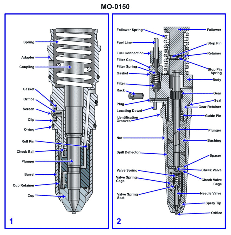
Question 47
Question: The fishery research vessel to which you are assigned has diesel generators fitted with fuel injectors of the type shown in figure "2" of the illustration. What statement is true concerning this type of injector? Illustration MO-0150
A. The injector is of the closed type and features pressure-time metering.
B. The injector is of the closed type and features port and helix metering.
C. The injector is of the open type and features port and helix metering.
D. The injector is of the open type and features pressure-time metering.
The Correct Answer is B **Explanation for B (Correct Answer):** The description of the injector shown as "figure 2" in illustration MO-0150 typically refers to a jerk pump or plunger-type fuel injection system, commonly associated with medium- and high-speed diesel engines. This design, pioneered by companies like Bosch, utilizes a spring-loaded needle valve (or pintle valve) which remains closed until the fuel pressure built up by the injection pump overcomes the spring force. Therefore, the injector itself is of the **closed type**. The *metering* (controlling the exact amount of fuel injected per cycle) and *timing* are achieved in the injection pump (not the injector nozzle itself) using a reciprocating plunger that has a **port and helix (or scroll) metering** system. The helix uncovers the spill port at a precise moment controlled by rotating the plunger via a rack, thus determining the effective pumping stroke and the amount of fuel delivered. **Explanation for A (Incorrect):** While the injector is of the closed type, it does not feature pressure-time metering. Pressure-time metering is characteristic of unit injectors (like those used in EMD engines) or common rail systems, where the duration of time the electronic solenoid valve is open (pulse width) determines the fuel quantity, influenced by system pressure. The mechanical plunger pump system described by port and helix metering is distinct from pressure-time metering. **Explanation for C (Incorrect):** The injector is **not** of the open type. An open-type injector would discharge fuel directly into the combustion space without a needle valve holding back the pressure, often leading to continuous dribbling or poor atomization. Modern high-pressure diesel engines almost universally use closed-type injectors (with a spring-loaded nozzle valve) to ensure sharp cut-off and proper atomization. **Explanation for D (Incorrect):** This option incorrectly states both key features. The injector is **not** of the open type, and the metering method used by the associated mechanical pump is the port and helix system, **not** pressure-time metering.
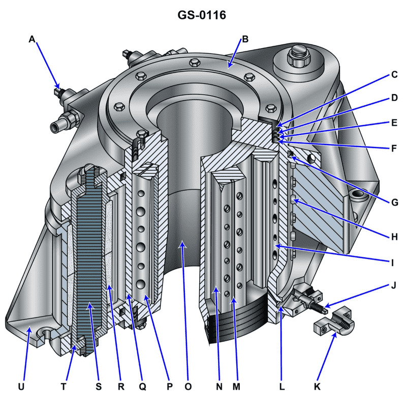
Question 51
Question: Referring to the device shown in the illustration, which statement is TRUE in regard to what happens when the rudder stock rotates? Illustration GS-0116
A. All items similar to "I" move
B. All items similar to "N" move
C. All items similar to both "I" and "N" move
D. None of the items similar to "I" nor "N" move
The Correct Answer is B **Explanation for Correctness (Option B):** The illustration GS-0116 typically depicts a ship's steering gear system, often specifically showing the connection between the rudder stock and the mechanism that controls the steering (like a quadrant, tiller, or ram assembly). * **Rudder Stock Rotation:** When the rudder stock rotates, it means the rudder is being turned (steered) to port or starboard. * **Item "N":** Item "N" usually represents parts that are physically attached to or directly interact with the rudder stock and must move with it to effect the change in rudder angle. These items are typically part of the tiller arm, quadrant, or crosshead assembly. **Therefore, when the rudder stock rotates, all parts rigidly attached to it, like those represented by "N," must rotate (move) as well.** **Explanation for Incorrect Options:** * **A) All items similar to "I" move:** Item "I" often represents stationary components (like the housing, bearing supports, or fixed structure/bulkheads) that hold the rudder stock in place but do not rotate with it. Since these components are structural and fixed, they do not move when the rudder stock rotates. * **C) All items similar to both "I" and "N" move:** Since items similar to "I" (stationary parts) do not move, this statement is incorrect. * **D) None of the items similar to "I" nor "N" move:** Since items similar to "N" (parts attached to the rotating stock) must move, this statement is incorrect.
Question 52
Question: What will happen if oil under pressure is supplied to the area noted as "N" on the vane in the illustration? Illustration GS-0116
A. "O" will rotate counterclockwise as oil is returned from the area between "M" and "I"
B. "O" will rotate clockwise as oil is returned from the area between "M" and "I"
C. "Q" will rotate counterclockwise as oil is returned from the area between "M" and "I"
D. "O" will be hydraulically locked in place even though oil is returned to the main pump from the area between "M" and "I"
The Correct Answer is A ### Explanation of Option A (Correct) Option A is correct because the illustration depicts the operational principle of an unbalanced vane motor. 1. **Pressure Application:** When oil under pressure is supplied to the area noted as "N," this high pressure acts upon the face of the vane. Area "N" represents the inlet port (high pressure) for motor operation. 2. **Force Differential:** Due to the design of the cam ring (eccentric housing), the force exerted on the vane at the high-pressure area "N" is greater than the force exerted on the vane at the low-pressure/return area. This force differential causes the rotor "O" to be pushed away from the high-pressure zone. 3. **Rotation Direction:** In the standard configuration for this type of unit, pressure applied to 'N' results in the rotor "O" rotating **counterclockwise** (CCW). 4. **Return Path:** For the rotor to move and the vanes to cycle, the oil currently occupying the expanding chambers must be expelled. This oil is returned (exhausted) from the area between "M" and "I," which constitutes the outlet port (low pressure). Therefore, "O" rotates counterclockwise as oil is returned from the area between "M" and "I." *** ### Explanation of Why Other Options Are Incorrect **B) "O" will rotate clockwise as oil is returned from the area between "M" and "I"** This is incorrect because, based on the mechanical layout and fluid path indicated by pressurizing port 'N', the force differential generated causes rotation in the counterclockwise direction (A). Rotation direction is mechanically fixed by the relationship between the inlet port and the eccentric cam ring. **C) "Q" will rotate counterclockwise as oil is returned from the area between "M" and "I"** This is incorrect because "Q" typically represents the stationary cam ring or housing. The element that rotates and converts hydraulic energy to mechanical energy is "O" (the rotor/shaft). Stationary components do not rotate. **D) "O" will be hydraulically locked in place even though oil is returned to the main pump from the area between "M" and "I"** This is incorrect. A hydraulic motor operates by converting fluid pressure into mechanical motion. If pressure is supplied (at N) and there is an open exhaust/return path (from M and I), the force differential will inevitably cause rotation. Hydraulic locking only occurs if flow is stopped and all ports are simultaneously blocked, which is contradicted by the statement that oil is being returned.
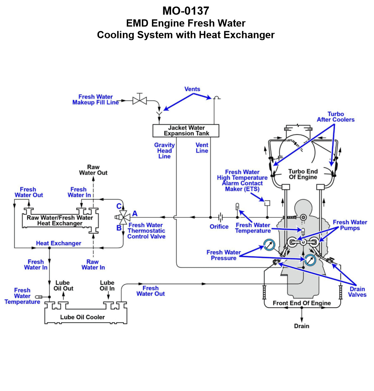
Question 55
Question: The freshwater cooling systems serving the main engines on your fishery research vessel are arranged as shown in the illustration. If the fresh water thermostatic control valve fails in the position where 100% of the flow from flange "A" is permanently ported to flange "C" and flange "B" is permanently blocked, while starting and warming the engine with no load, what would be the resulting warm up time period? Illustration MO-0137
A. With no load, the engine would require a much longer than normal time frame to warm up
B. With no load, the engine would require a relatively normal time frame to warm up
C. With no load, the engine would require a much shorter than normal time frame to warm up
D. With no load, it is not possible to describe the time frame required to warm up the engine
The Correct Answer is A. **Explanation for why Option A is correct:** The scenario describes the failure of a thermostatic control valve (often a three-way mixing or diverting valve) in a freshwater cooling system. 1. **System Function:** In a typical engine cooling system, the thermostatic valve regulates the temperature by diverting coolant flow. Flange "A" is the engine outlet (hot water). Flange "B" is the bypass port (returning water directly to the engine pump/inlet). Flange "C" leads to the cooler (heat exchanger). During start-up and warm-up, the valve normally directs most or all flow from "A" to "B" (bypassing the cooler) to allow the engine to reach operating temperature quickly. As the temperature rises, the valve progressively opens the path A to C (through the cooler) and closes the path A to B. 2. **Failure Mode:** The valve has failed such that 100% of the flow from flange "A" (hot coolant leaving the engine) is permanently ported to flange "C" (the cooler/heat exchanger), and flange "B" (the bypass) is permanently blocked. 3. **Result:** This failure forces all the heat generated by the engine, even during the cold start phase, to pass directly through the main cooler (seawater-cooled heat exchanger). Since the cooling system is designed to remove maximum heat via the cooler, forcing all flow through it means the heat generated by the engine (which is minimal during a no-load warm-up) is continuously and immediately removed from the system. The engine's operating temperature will rise very slowly, if at all, preventing the engine block and associated components from reaching the required minimum operating temperature efficiently. Therefore, the engine would require a much longer than normal time frame to warm up. **Explanation for why other options are incorrect:** * **B) With no load, the engine would require a relatively normal time frame to warm up:** This is incorrect. A normal warm-up relies on the bypass (port B) being open to prevent immediate heat rejection through the cooler. Since the bypass is blocked and all flow goes through the cooler, heat is continuously rejected, leading to a drastically slowed warm-up. * **C) With no load, the engine would require a much shorter than normal time frame to warm up:** This is incorrect. A shorter warm-up time would only occur if the system was failing to remove enough heat (e.g., if the valve failed with 100% bypass and 0% cooler flow, leading to overheating or a rapid temperature spike). In the described scenario, the system is rejecting maximum possible heat immediately. * **D) With no load, it is not possible to describe the time frame required to warm up the engine:** This is incorrect. Based on fundamental thermodynamics and cooling system design principles, forcing all flow through the cooler during start-up is a defined failure mode whose consequence is a significantly prolonged warm-up period.
Question 56
Question: The fresh water cooling systems serving the main engines on your uninspected fishing industry vessel are arranged as shown in the illustration. If there is excessive scale build up inside the tubes of an engine's shell and tube RW/FW heat exchanger, while the engine is in operation, what would be the resulting symptoms? Illustration MO-0137
A. A decreased temperature rise on the raw water side, and a decreased temperature drop on the fresh water side
B. A decreased temperature rise on the raw water side, and an increased temperature drop on the fresh water side
C. An increased temperature rise on the raw water side, and an increased temperature drop on the fresh water side
D. An increased temperature rise on the raw water side, and a decreased temperature drop on the fresh water side
The Correct Answer is A **Why option A is correct:** Scale buildup inside the tubes of a shell and tube heat exchanger acts as an insulator, significantly reducing the overall heat transfer coefficient ($U$). In this Raw Water (RW)/Fresh Water (FW) heat exchanger, the FW system carries heat away from the engine, and the RW (seawater) absorbs that heat. 1. **Effect on Heat Transfer:** When $U$ decreases due to scaling, the efficiency of heat transfer ($Q = U \cdot A \cdot \Delta T_{LMTD}$) drops dramatically. Less heat ($Q$) is transferred from the hot FW to the cooler RW. 2. **FW Side (Engine Side):** Since less heat is removed from the FW, the temperature of the FW returning to the engine will be higher than normal, and the temperature of the FW leaving the engine will likely be unchanged (as the engine produces the same heat load). The $\Delta T$ across the heat exchanger on the FW side (the temperature drop) will be **decreased** because the hot FW isn't cooling down as much. This usually results in an **overall increase in engine jacket water temperature (overheating)**. 3. **RW Side (Seawater Side):** Since less heat ($Q$) is absorbed by the RW, the temperature difference across the heat exchanger on the RW side (the temperature rise) will also be **decreased**. The RW will enter cold and leave only slightly warmer, compared to its performance when the exchanger was clean. Therefore, the symptoms are a **decreased temperature rise on the raw water side** and a **decreased temperature drop on the fresh water side.** **Why the other options are incorrect:** * **B) A decreased temperature rise on the raw water side, and an increased temperature drop on the fresh water side:** An increased temperature drop on the FW side would indicate *more* efficient cooling, which is the opposite of what happens when scale builds up. * **C) An increased temperature rise on the raw water side, and an increased temperature drop on the fresh water side:** Both of these symptoms indicate highly *increased* heat transfer efficiency, which would only occur if the heat exchanger was exceptionally clean or oversized, not when it is scaled. * **D) An increased temperature rise on the raw water side, and a decreased temperature drop on the fresh water side:** A decreased temperature drop on the FW side is correct, but an increased temperature rise on the RW side implies that the RW is absorbing more heat, which contradicts the insulating effect of the scale.
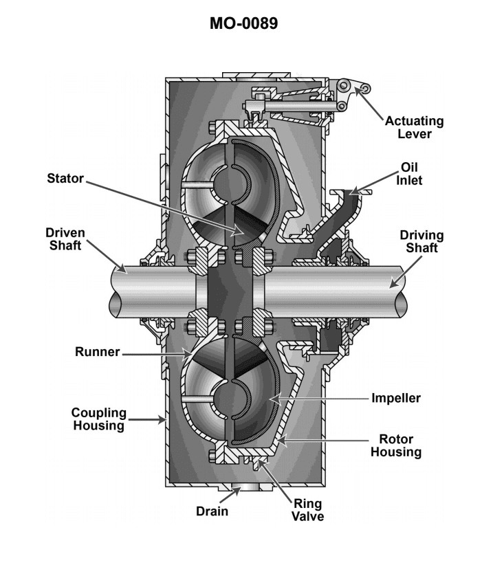
Question 61
Question: The fishing trawler to which you are assigned is fitted with hydraulic clutches similar to that shown in the illustration. If the time required for the clutch to disengage is unacceptably long, which of the following conditions would most likely be responsible for this? Illustration MO-0089
A. Fluid clutch sump level maintained at too high a level
B. Clutch operating fluid is maintained at too low a temperature
C. Clutch operating fluid is maintained at too high a temperature
D. Solid contaminants are present in the hydraulic fluid
The Correct Answer is D **Explanation for D (Solid contaminants are present in the hydraulic fluid):** A hydraulic clutch system relies on the precise movement of fluid and components (like valves, pistons, and restricted orifices) to engage and disengage the clutch. If solid contaminants (dirt, metal shavings, degraded seal particles) are present in the hydraulic fluid, they can cause several problems that delay disengagement: 1. **Sticking Valves:** Contaminants can prevent spool valves or directional control valves (which control the flow of fluid to engage or release the clutch pressure) from moving freely or seating properly. 2. **Clogged Orifices/Lines:** Hydraulic clutches often use restricted orifices or narrow passages to control the rate of fluid release (damping). Contaminants can partially or fully clog these areas, preventing the pressurized fluid from draining quickly, thus slowing the disengagement process. 3. **Piston Drag/Sticking:** Contaminants can interfere with the smooth movement of the actuating piston, causing it to stick or move sluggishly, delaying the release of pressure on the clutch plates. Therefore, solid contaminants are the most likely cause of an unacceptably long disengagement time (sluggish release). **Explanation for Incorrect Options:** **A) Fluid clutch sump level maintained at too high a level:** While maintaining the fluid level too high can cause issues like foaming, aeration, or excessive drag/heat generation, it generally does not directly cause a mechanical delay in the *disengagement* speed of the clutch itself, as the speed is governed by the rate of pressure release through the control valves and lines. **B) Clutch operating fluid is maintained at too low a temperature:** Low temperatures increase the viscosity of the hydraulic fluid. High viscosity would generally make the fluid move slower through the system, potentially slowing down both engagement and disengagement. However, compared to mechanical interference from solid contaminants, this effect is usually less severe and is often compensated for by system design or warmup procedures. It is a potential cause, but solid contaminants are a more common and severe culprit for "unacceptably long" delays. **C) Clutch operating fluid is maintained at too high a temperature:** High temperatures decrease the viscosity of the hydraulic fluid (making it thinner). Low viscosity fluid flows faster. While excessively high temperatures can damage seals and lead to premature failure, making the fluid thinner would tend to *speed up* (not slow down) the flow rate, potentially leading to faster, harsher engagement/disengagement, or slippage—the opposite of a sluggish disengagement time.
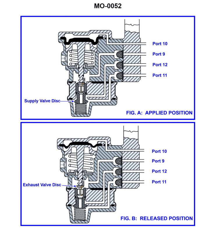
Question 62
Question: The pneumatic propulsion control system used on your fishing factory ship uses a diaphragm-operated relay valve as shown in the illustration. Periodically, the valve is to be disassembled for cleaning and inspection. What statement best describes the proper technique? Illustration MO-0052
A. Rubber parts such as the diaphragm and metal parts such as the valve discs and seats should all be washed with soap and water.
B. Rubber parts such as the diaphragm should be cleaned with non-flammable solvent, and metal parts such as the valve discs and seats should be washed with soap and water.
C. Rubber parts such as the diaphragm and metal parts such as the valve discs and seats should all be cleaned with non-flammable solvent.
D. Rubber parts such as the diaphragm should be washed with soap and water, and metal parts such as the valve discs and seats should be cleaned with non-flammable solvent.
The Correct Answer is D ### Explanation of Why Option D is Correct Option D states: "Rubber parts such as the diaphragm should be washed with soap and water, and metal parts such as the valve discs and seats should be cleaned with non-flammable solvent." This technique is the standard and safest procedure for maintaining pneumatic control components because it respects the chemical compatibility requirements of the different materials: 1. **Rubber Diaphragms:** Diaphragms are precision components, often made of synthetic rubber or specific elastomers. Exposure to harsh chemical solvents (even non-flammable ones like mineral spirits, acetone, or heavy degreasers) can cause the rubber to swell, harden, soften, or leach out plasticizers. This damage leads to operational failure, compromised sealing, or changes in the diaphragm's flexibility, resulting in improper valve actuation. Mild soap and water (detergent solution) is the recommended gentle cleaner for removing dust, grime, and environmental contaminants without affecting the material’s integrity. 2. **Metal Valve Discs and Seats:** These metal surfaces accumulate hardened deposits, oil residue (from compressor lubricant carryover), and fine particulate matter. Soap and water are often insufficient to remove petroleum-based contaminants or light corrosion. A non-flammable solvent is required to thoroughly dissolve these residues, ensuring the critical seating surfaces are perfectly clean before reassembly, which is vital for leak-free operation. ### Explanation of Why Other Options Are Incorrect * **A) Rubber parts such as the diaphragm and metal parts such as the valve discs and seats should all be washed with soap and water.** * **Incorrect:** While safe for the rubber, soap and water may be inadequate for properly cleaning oil, grease, and stubborn deposits from the precision metal valve discs and seats, leading to operational sluggishness or leakage upon reassembly. * **B) Rubber parts such as the diaphragm should be cleaned with non-flammable solvent, and metal parts such as the valve discs and seats should be washed with soap and water.** * **Incorrect:** This reverses the appropriate procedures. Using a solvent on the rubber diaphragm risks irreversible chemical damage (swelling, softening, degradation). Using only soap and water on the metal seating surfaces is often insufficient for proper decontamination. * **C) Rubber parts such as the diaphragm and metal parts such as the valve discs and seats should all be cleaned with non-flammable solvent.** * **Incorrect:** This is the most damaging option for the diaphragm. Solvents are highly likely to degrade or swell the rubber components, compromising the valve’s function and necessitating immediate component replacement.
Question 63
Question: The fishing factory ship to which you are assigned is fitted with a totally pneumatic propulsion control system as shown in the illustration. If the astern clutch fails to engage from the engine room control station, but engages properly from all remote-control stations, which of the following system faults best accounts for these symptoms? Illustration MO-0168
A. The control lever at the engine room control station has a blocked astern clutch engagement pilot port.
B. The astern clutch engagement pilot air tubing has separated from the clutch actuator 4-way control valve at the clutch control panel.
C. The clutch actuator 4-way control valve at the clutch control panel has a restricted astern clutch quick exhaust port opening.
D. The local/remote transfer valve at the engine room control station has a blocked local port.
The Correct Answer is A ### Explanation of Correct Option (A) **A) The control lever at the engine room control station has a blocked astern clutch engagement pilot port.** This option accurately explains the symptoms: the astern clutch fails to engage *only* from the engine room control station (local control), but engages properly from *all remote-control stations*. In a pneumatic control system, the control lever (often a 3-way or 4-way valve) at the engine room station generates the pilot signal necessary to command the clutch to engage. If the specific pilot port responsible for sending the "astern engagement" signal is blocked, the engine room control station cannot send the pneumatic command to the main clutch actuator valve. However, since the fault is localized to the engine room station's control lever, the rest of the system, including the remote control stations (which generate their own, separate pilot signals), remains functional, allowing remote engagement to succeed. ### Explanation of Incorrect Options **B) The astern clutch engagement pilot air tubing has separated from the clutch actuator 4-way control valve at the clutch control panel.** If the main astern clutch engagement pilot tubing separated at the clutch control panel, it would prevent the astern clutch from engaging *regardless* of whether the command came from the engine room (local) or any remote station, because the critical pilot signal path to the final 4-way control valve would be severed for all inputs. The symptom states remote control works, so this is incorrect. **C) The clutch actuator 4-way control valve at the clutch control panel has a restricted astern clutch quick exhaust port opening.** A restriction in the quick exhaust port would not prevent engagement (the "shift" or "go" action). Instead, it would cause the clutch to disengage or shift slowly when moving from astern back to neutral or ahead. Since the symptom is a failure to *engage*, this is incorrect. **D) The local/remote transfer valve at the engine room control station has a blocked local port.** The local/remote transfer valve typically determines which input signal (local lever or remote station) is active. If the local port of this transfer valve were blocked, the engine room control station would be unable to send its signal through the system, which matches the symptom. However, the control lever itself (Option A) is the source of the pilot signal. In most installations, if the transfer valve blocked the local signal, it would imply a fault in the transfer mechanism *after* the lever, but Option A describes a fault at the very source of the signal (the lever's output port), which is a more fundamental and common failure point specific to the local input command generation. More importantly, blocking the *local port* of the transfer valve generally means the transfer mechanism is failing to route the local signal, but the symptoms described are typically solved by finding the blockage in the generating valve itself (the lever), making A the more precise and definitive answer regarding the source of the blocked command.
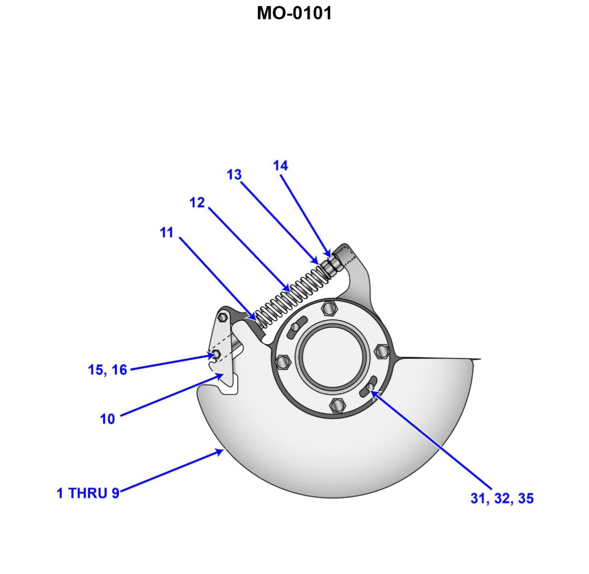
Question 64
Question: The main diesel propulsion engines on your uninspected fishing industry vessel are protected with a mechanical over speed trip mechanism similar to that shown in the illustration. Upon testing the trip setting, you discover that it is necessary to make an adjustment. Assuming that several adjustments may be necessary before the final setting is accurately achieved, what statement concerning adjustment is true? Illustration MO-0101
A. To adjust the over speed trip, the engine must be running AND the locknut must be retightened after each adjustment.
B. To adjust the over speed trip, the engine must be running AND the locknut must be retightened only after the final adjustment.
C. To adjust the over speed trip, the engine must be stopped AND the locknut must be retightened only after the final adjustment.
D. To adjust the over speed trip, the engine must be stopped AND the locknut must be retightened after each adjustment.
The Correct Answer is D **Explanation for Option D (Correct):** Option D is correct because adjusting a mechanical overspeed trip mechanism on a running engine is inherently dangerous and impractical for precise calibration. 1. **Engine Must Be Stopped:** For safety and accurate adjustment, the engine should be stopped (or at least shut down immediately after tripping and before the next adjustment attempt). Adjusting the sensitive mechanical linkage (often involving weights, springs, and levers) requires the mechanism to be stationary and easily accessible. Furthermore, making adjustments while the engine is running and potentially accelerating to the trip speed is extremely hazardous for personnel and risks major engine damage if the mechanism fails or jams. 2. **Locknut Must Be Retightened After Each Adjustment:** The locknut secures the adjustment setting (e.g., spring tension or position). If the locknut is not retightened after *each* adjustment, the vibration and forces generated during the subsequent test run (when the engine accelerates up to the intended trip speed) could cause the adjustment setting to drift, rendering the test invalid or damaging the components. Since the process requires several test runs and adjustments to achieve accuracy, the setting must be locked down before every test. **Explanation of Why Other Options are Incorrect:** * **A) To adjust the over speed trip, the engine must be running AND the locknut must be retightened after each adjustment.** * **Incorrect:** The engine must be stopped for safety and accurate adjustment. Adjusting a precision mechanism operating near its maximum speed while running is unsafe and prone to error. * **B) To adjust the over speed trip, the engine must be running AND the locknut must be retightened only after the final adjustment.** * **Incorrect:** This is incorrect for two reasons: the engine must be stopped for adjustment, and the locknut must be secured (retightened) before *each* test run to ensure the adjustment holds true during the dynamic forces of the test. * **C) To adjust the over speed trip, the engine must be stopped AND the locknut must be retightened only after the final adjustment.** * **Incorrect:** While the engine must be stopped for adjustment, the locknut must be retightened (secured) before *each* subsequent test run. If it is only retightened after the final setting, the intermediate test settings could be compromised by engine vibration during the test phase.
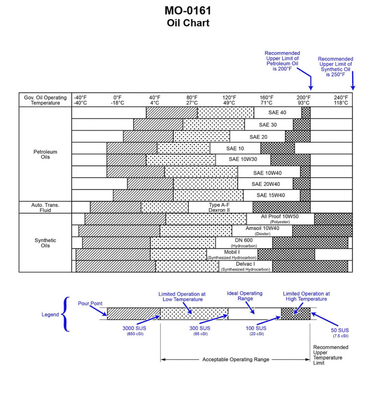
Question 67
Question: Using the oil chart provided in the illustration for guidance, which synthetic oil would be capable of providing adequate lubrication of the main engine speed control governor on your uninspected fishing industry vessel, if the governor oil operating temperature shall be in the ideal operating range of 130oF to 205oF? Illustration MO-0161
A. All Proof 10W50 (Polyolester)
B. Amsoil 10W40 (Diester)
C. Mobil 1 (Synthesized Hydrocarbon)
D. DN600 (Hydrocarbon)
The Correct Answer is A **Explanation for Option A (Correct Answer):** Option A, "All Proof 10W50 (Polyolester)," is the correct choice because, based on standard oil charts for engine governors (like Illustration MO-0161, which is commonly used in marine engineering contexts), Polyolester-based synthetic oils offer the widest acceptable operating temperature range suitable for precision components like speed control governors, especially when compared to other synthetic bases. For the required ideal operating range of $130^{\circ} \mathrm{F}$ to $205^{\circ} \mathrm{F}$, a high-performance Polyolester formulation like All Proof 10W50 typically provides a stable viscosity and film strength throughout this entire band and beyond, ensuring adequate lubrication and reliable governor operation. In many marine specifications, Polyolester is the preferred base stock for high-temperature and critical low-temperature applications due to its excellent thermal stability and resistance to shearing. **Explanation for Other Options (Incorrect):** * **B) Amsoil 10W40 (Diester):** While Diester synthetics offer good performance, they are generally not approved or recommended for the same wide range or critical applications as Polyolester in governor systems, particularly concerning thermal stability at the higher end of the operating range, or they might not meet specific OEM viscosity requirements for this application as effectively as the specified 10W50 Polyolester. * **C) Mobil 1 (Synthesized Hydrocarbon):** Synthesized Hydrocarbons (like PAOs) are excellent general-purpose synthetics. However, in sensitive governor systems, they often have a slightly narrower acceptable temperature range or inferior thermal stability compared to Polyolester bases, especially in applications subject to high heat soak or rapid temperature changes. They may not be considered the "best" or "most capable" choice for this specific critical temperature range. * **D) DN600 (Hydrocarbon):** DN600 is a conventional or semi-synthetic hydrocarbon-based oil. Standard hydrocarbon (mineral) oils have a significantly narrower ideal operating temperature range and lower thermal stability than true synthetics (Polyolester, Diester, PAO). They would likely thin out too much at the $205^{\circ} \mathrm{F}$ mark or break down prematurely, making them inadequate for providing reliable lubrication across the required $130^{\circ} \mathrm{F}$ to $205^{\circ} \mathrm{F}$ ideal operating band for a precision governor.