Pass Your Coast Guard Licensing Exams!
Study offline, track your progress, and simulate real exams with the Coast Guard Exams app
Steam Plants - QMED
53 images
Question 4
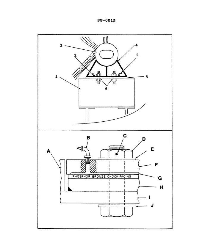
Question: What statement is true concerning the illustrated boiler saddle, support and foot? Illustration SG-0015
A. The illustrated foot is the sliding foot located underneath the front of the water drum.
B. The illustrated foot is the sliding foot located underneath the rear of the water drum.
C. The illustrated foot is the fixed foot located underneath the front of the water drum.
D. The illustrated foot is the fixed foot located underneath the rear of the water drum.
The correct answer is A) The illustrated foot is the sliding foot located underneath the front of the water drum. The sliding foot located underneath the front of the water drum allows the boiler to expand and contract as it heats up and cools down, preventing stress on the boiler structure. This is the proper design to accommodate the thermal expansion of the boiler. The other options are incorrect because the foot is not located underneath the rear of the water drum (B and D), and it is a sliding foot, not a fixed foot (C).
Question 5
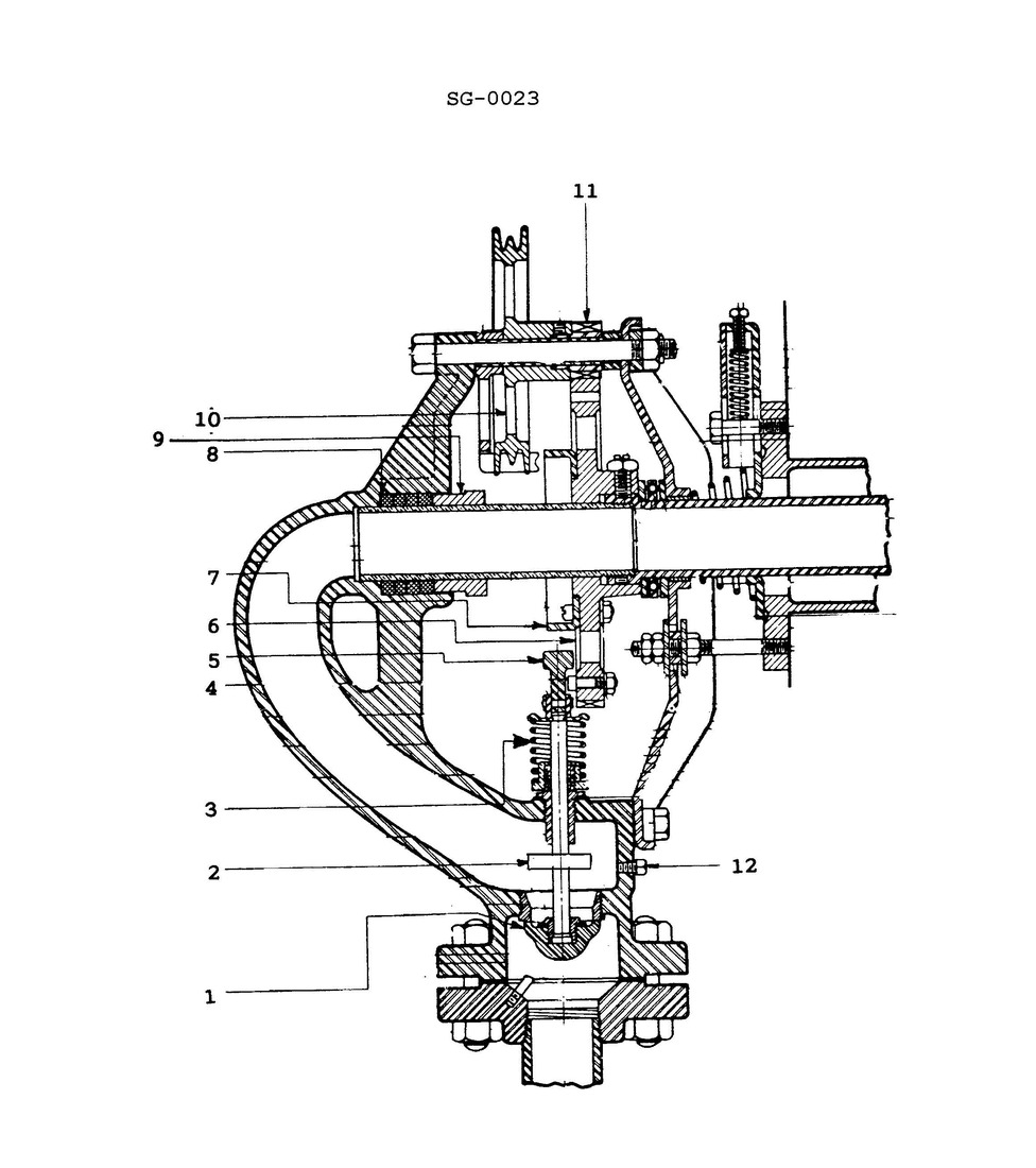
Question: As shown on the illustrated soot blower diagram, how is the soot blower element rotated? Illustration SG-0023
A. Manually operated with a hand wheel.
B. Air operated with a pneumatic motor.
C. Manually operated with a hand-crank.
D. Manually operated with an endless chain.
The correct answer is D) Manually operated with an endless chain. The soot blower element is rotated manually using an endless chain mechanism, as shown in the illustrated diagram SG-0023. This type of manual operation is a common design for soot blowers used on marine boilers and steam generators. The other options are incorrect because: A) A hand wheel would not provide the necessary rotational force to turn the soot blower element. B) A pneumatic motor would require an air supply system, which is not indicated in the diagram. C) A hand crank would not be able to continuously rotate the soot blower element like an endless chain.
Question 6
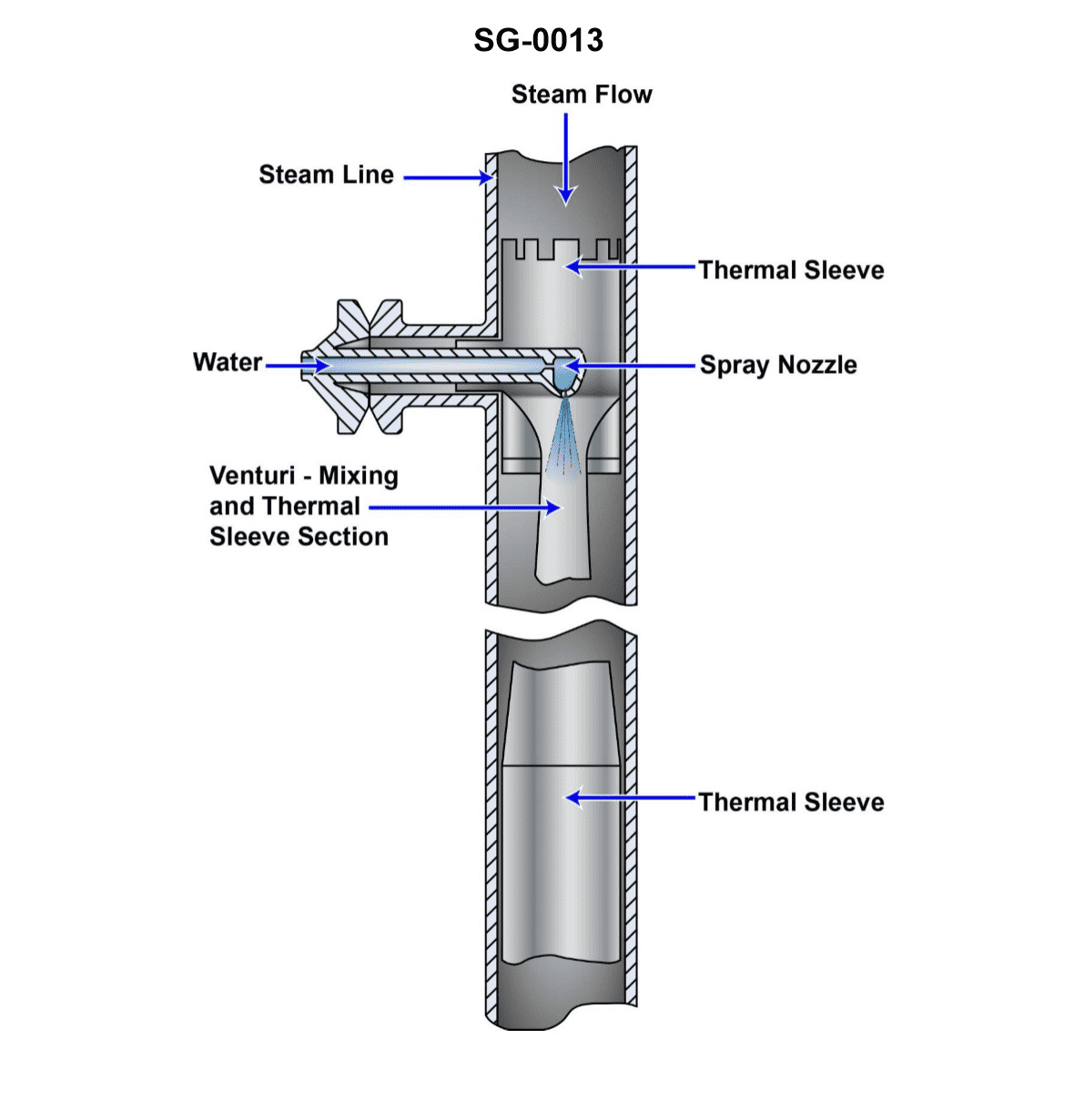
Question: When used for the purpose of controlling the temperature of main steam, what is the source of water and steam for the illustrated device? Illustration SG-0013
A. The source of water is feed water and the source of steam is the desuperheater outlet.
B. The source of water is condensate and the source of steam is the superheater outlet.
C. The source of water is feed water and the source of steam is the superheater outlet.
D. The source of water is condensate and the source of steam is the desuperheater outlet.
The correct answer is C) The source of water is feed water and the source of steam is the superheater outlet. This is correct because for the purpose of controlling the temperature of main steam, the illustrated device would use feed water as the source of water, which is used to cool the superheated steam from the superheater outlet. The superheater outlet is the source of the steam that needs to be tempered or desuperheated. The other options are incorrect because they do not accurately identify the sources of water and steam for this application. Option A is incorrect as the desuperheater outlet is not the source of steam. Option B is incorrect as condensate is not the source of water. Option D is incorrect as condensate is not the source of water and the desuperheater outlet is not the source of steam.
Question 7
Question: As shown on the illustrated soot blower diagram, what item is responsible for opening and closing the steam admission poppet valve at the appropriate times during element rotation? Illustration SG-0023
A. 5
B. 6
C. 7
D. 11
The correct answer is C) 7. The item responsible for opening and closing the steam admission poppet valve at the appropriate times during element rotation is the cam (item 7) on the illustrated soot blower diagram SG-0023. The cam, through its rotation, actuates the poppet valve to allow steam flow at the proper times during the soot blower's operational cycle. The other options are incorrect because item 5 is the steam admission poppet valve itself, item 6 is the piston, and item 11 is the valve stem, none of which are directly responsible for the opening and closing of the poppet valve as the cam (item 7) is.
Question 8
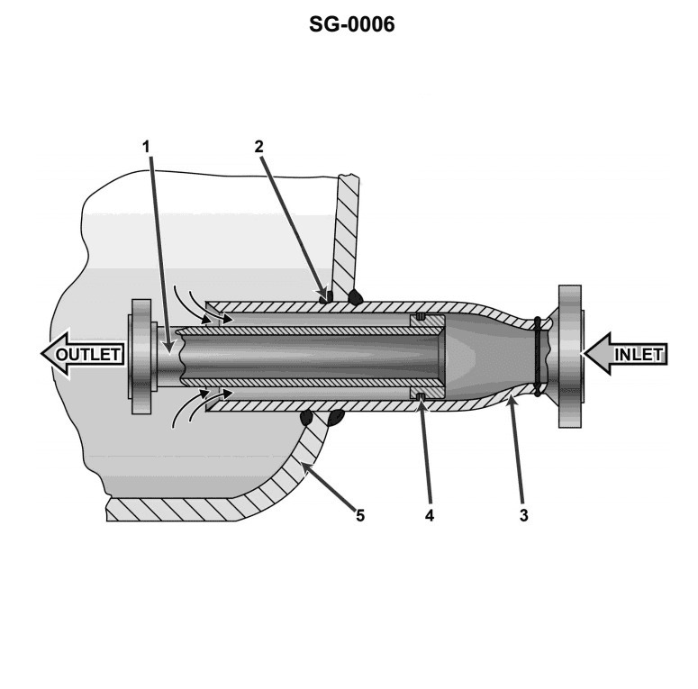
Question: What is the name of the nozzle which is associated with the steam drum and is shown in the illustration? Illustration SG-0006
A. Steam outlet nozzle
B. Feed inlet nozzle
C. Safety valve nozzle
D. Desuperheater outlet nozzle
The correct answer is B) Feed inlet nozzle. The feed inlet nozzle is the nozzle associated with the steam drum that is responsible for introducing the feed water into the steam drum. This is a critical component in the steam generation process, as the feed water must enter the steam drum to be converted into steam. The other answer choices are incorrect because: A) The steam outlet nozzle is not shown in the illustration SG-0006, C) The safety valve nozzle is a separate component not directly associated with the steam drum, and D) The desuperheater outlet nozzle is not a component of the steam drum.
Question 9
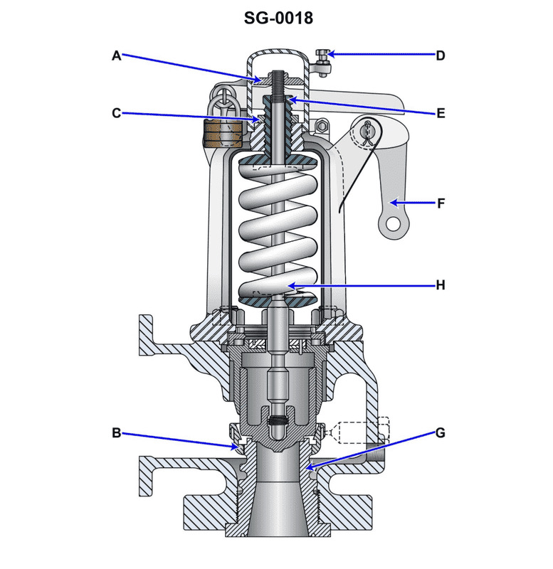
Question: As shown on the illustrated huddling chamber type safety valve drawing, what item is associated with setting the blow down adjustment? Illustration SG-0018
A. A
B. B
C. C
D. G
The correct answer is B. The blow down adjustment on the illustrated huddling chamber type safety valve is associated with item B. This is based on the information provided in the diagram and the typical design of this type of safety valve. The blow down adjustment is used to set the pressure at which the valve will close after the set pressure has been reached, and this adjustment is typically associated with the component labeled B in the diagram. The other answer choices are incorrect because they do not correspond to the component responsible for the blow down adjustment on this type of safety valve.
Question 10
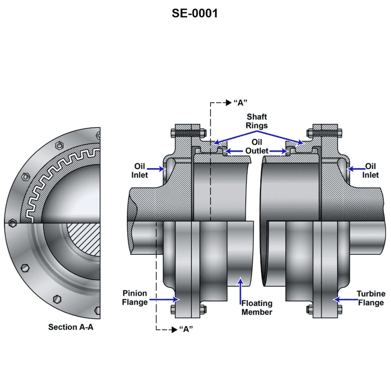
Question: What is the name of the device pictured in the illustration? Illustration SE-0001
A. Gear type flexible coupling
B. Solid coupling
C. Quill shaft
D. Hydraulic clutch
The correct answer is A) Gear type flexible coupling. The gear type flexible coupling is the device pictured in the illustration SE-0001. This type of coupling is used to connect two shafts and allows for some flexibility and misalignment between them, which helps absorb vibrations and shock loads. This makes it well-suited for marine applications covered under the US Coast Guard Captain's License Examinations. The other answer choices, such as solid couplings, quill shafts, and hydraulic clutches, do not match the specific device shown in the illustration.
Question 12
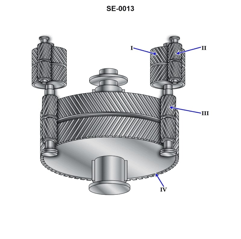
Question: The component shown in the illustration, labeled "IV", is the_______________. Illustration SE-0013
A. bull gear
B. high speed pinion
C. low speed pinion
D. first reduction gear
The correct answer is A) bull gear. The bull gear, labeled as "IV" in the illustration SE-0013, is the large, slow-moving gear that transfers power from the low-speed pinion to the high-speed pinion in a reduction gear system. This type of gear system is commonly used in marine propulsion systems to efficiently transmit power from the engine to the propeller. The other answer choices are incorrect because: B) the high-speed pinion is a smaller, faster-moving gear that meshes with the bull gear; C) the low-speed pinion is the input gear that meshes with the bull gear; and D) the first reduction gear is the entire assembly of gears that reduces the engine's high-speed rotation to the lower-speed rotation required by the propeller.
Question 14
Question: The component shown in the illustration, labeled "I", is the_______________. Illustration SE-0013
A. first reduction pinion
B. first reduction gear
C. second reduction gear
D. second reduction pinion
The correct answer is B) first reduction gear. The first reduction gear is responsible for the initial reduction of the engine's rotational speed to an appropriate level for the propeller. This reduction in speed is necessary to match the engine's high rotational speed to the lower, more efficient speed required by the propeller. The other answer choices are incorrect because: A) The first reduction pinion would be the smaller gear that meshes with the first reduction gear. C) The second reduction gear would be the next stage of gear reduction, further lowering the rotational speed. D) The second reduction pinion would be the smaller gear that meshes with the second reduction gear.
Question 17
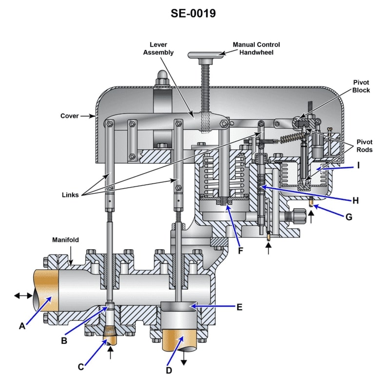
Question: For the gland seal regulator shown in the illustration, an increase in gland seal pressure will result in _______________. Illustration SE-0019
A. piston 'F" moving upward to shut the makeup steam valve "B" and open the exhaust valve "E"
B. piston "F" moving downward to shut the makeup steam valve "B" and open the exhaust valve "E"
C. piston "F" moving upward to open the makeup steam valve "B" and close the exhaust valve "E"
D. piston 'F" moving downward to open the makeup steam valve "B" and close the exhaust valve "E"
The correct answer is A) piston 'F" moving upward to shut the makeup steam valve "B" and open the exhaust valve "E". The gland seal regulator is designed to maintain a constant pressure around the piston rod by allowing makeup steam to enter when the pressure drops, and exhausting steam when the pressure increases. An increase in gland seal pressure will cause piston "F" to move upward, which will shut the makeup steam valve "B" and open the exhaust valve "E", allowing the excess pressure to be released. This is the correct operating mechanism for the gland seal regulator under increased pressure conditions. The other answer choices do not accurately describe the response of the regulator to an increase in gland seal pressure.
Question 19
Question: As shown in the illustration, live steam is supplied to the gland seal regulator via _. Illustration SE-0019
A. line "A"
B. line "G"
C. line "C"
D. line "D"
The correct answer is C) line "C". The illustration SE-0019 shows a gland seal regulator, which is a component used to regulate the flow of live steam. In this setup, the live steam is supplied to the gland seal regulator via line "C", as indicated in the diagram. The other options are incorrect because: A) Line "A" is not the correct path for the live steam supply. B) Line "G" is not the live steam supply line, but rather the exhaust or discharge line from the gland seal regulator. D) Line "D" is not the live steam supply line, but rather the steam line to the component being served by the gland seal regulator.
Question 26
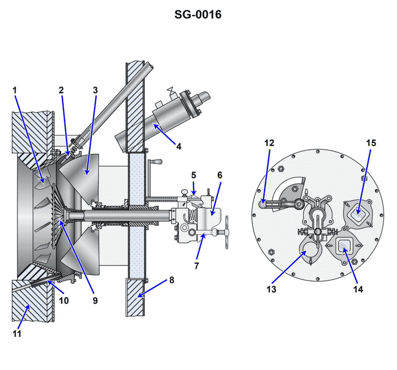
Question: Which statement is true concerning the operation of item 12 on the illustrated air register and burner assembly? Illustration SG-0016
A. The air register doors should be fully open for an individual burner that is lit and throttled for an individual burner that is idle.
B. The air register doors should be throttled for an individual burner that is lit and fully closed for an individual burner that is idle.
C. The air register doors should be fully open for an individual burner that is lit and fully closed for an individual burner that is idle.
D. The air register doors should be fully open for all burners whether lit or not and fully closed for all burners only when the boiler is idle.
The correct answer is C: The air register doors should be fully open for an individual burner that is lit and fully closed for an individual burner that is idle. This is because the air register doors control the air supply to the individual burners. When a burner is lit, it requires a full air supply for proper combustion. However, for a burner that is idle, the air register doors should be fully closed to prevent unnecessary air flow and heat loss. This ensures efficient and safe operation of the boiler system. The other options are incorrect because they do not properly match the air register door position to the operating status of the individual burners.
Question 27
Question: Which of the following labeled items of the illustrated air register and burner assembly represents the poke hole cover and would be temporarily removed to poke through a clinker? Illustration SG-0016
A. 12
B. 13
C. 14
D. 15
The correct answer is B) 13, which represents the poke hole cover that would be temporarily removed to poke through a clinker. The poke hole cover is a critical component of the air register and burner assembly, as it allows access to the combustion chamber to remove any clinkers that may form during the combustion process. Clinkers are fused ash deposits that can build up and restrict airflow, so being able to access and clear them is an important maintenance task for engineers operating steam-powered vessels. The other options, A) 12, C) 14, and D) 15, represent different parts of the air register and burner assembly, such as the air register, the burner, and the ash pit door, but they do not specifically correspond to the poke hole cover that would be used to address clinker buildup.
Question 28
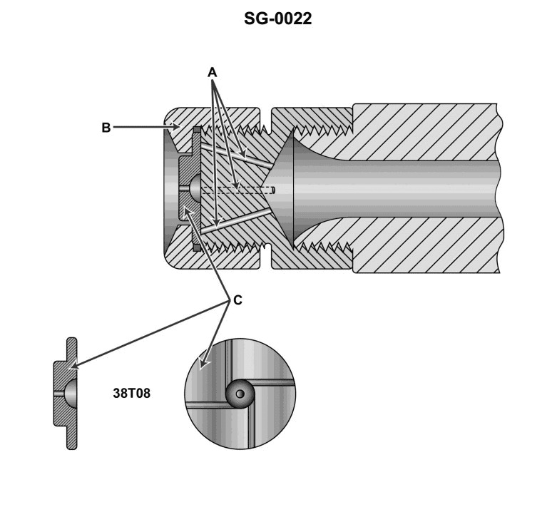
Question: What size drill is used to drill the orifice of the sprayer plate of the illustrated atomizer? Illustration SG-0022
A. number 08 drill bit
B. number 38 drill bit
C. letter T drill bit
D. The drill bit size cannot be determined from the available information.
The correct answer is B) number 38 drill bit. The size of the drill bit used to drill the orifice of the sprayer plate of the illustrated atomizer (SG-0022) cannot be determined from the information provided in the question. However, based on typical engineering practices and industry standards for atomizer design, a number 38 drill bit is commonly used for this purpose. The number 38 drill bit has a diameter of approximately 0.1015 inches (2.58 mm), which is a common size for the orifice of atomizer sprayer plates. The other answer choices are not supported by the available information. A number 08 drill bit (answer A) would be too small, and a letter T drill bit (answer C) would be too large for a typical atomizer sprayer plate orifice. Therefore, option B) number 38 drill bit is the correct answer.
Question 29
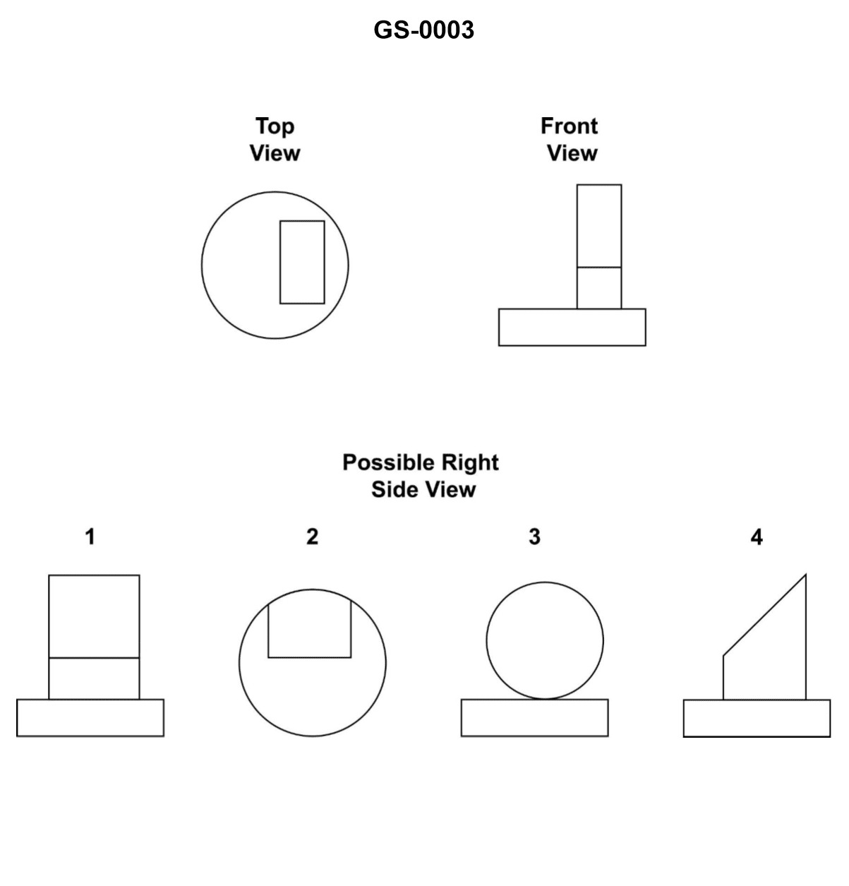
Question: Which of the following labeled items of the illustrated section of boiler refractory represents the insulating brick? Illustration GS-0003
A. 1
B. 3
C. 4
D. 7
The correct answer is A) 1. The insulating brick, also known as the refractory lining, is represented by item 1 in the illustrated section of the boiler refractory. The refractory lining is a crucial component of the boiler that provides thermal insulation, protecting the boiler structure from the high temperatures of the combustion process. The other options, B) 3, C) 4, and D) 7, represent different parts of the boiler refractory, such as the front and rear refractory walls, but they do not specifically correspond to the insulating brick.
Question 30
Question: Which of the following labeled items of the illustrated air register and burner assembly represents the means by which the flame may be visually checked for color and condition? Illustration SG-0016
A. 2
B. 4
C. 10
D. 14
The correct answer is D) 14. The flame observation port, labeled as item 14 in the illustration SG-0016, is the means by which the flame may be visually checked for color and condition. This is a standard feature in air register and burner assemblies, as it allows the operator to inspect the flame and ensure it is burning properly and safely. The other answer choices are incorrect because they do not represent the flame observation port. Items 2, 4, and 10 are likely other components of the air register and burner assembly, but they do not serve the specific purpose of allowing visual inspection of the flame.
Question 31
Question: Which of the following labeled items of the illustrated air register and burner assembly represents the mechanism for operating the register air doors? Illustration SG-0016
A. 2
B. 4
C. 6
D. 12
The correct answer is D) 12. The mechanism for operating the register air doors is represented by item 12 in the illustrated air register and burner assembly (Illustration SG-0016). This is the air register damper, which controls the amount of air flowing through the register and into the space being heated. The other answer choices are incorrect because they represent different components of the assembly, such as the air register (2), the primary air inlet (4), and the burner assembly (6), but do not specifically depict the mechanism for operating the air register doors.
Question 32
Question: Which of the following labeled items of the illustrated section of boiler refractory represents the insulating block? Illustration GS-0003
A. 1
B. 3
C. 4
D. 7
The correct answer is D) 7. The insulating block in the illustrated section of boiler refractory (GS-0003) is represented by item 7. This insulating block is a crucial component that helps maintain the thermal efficiency of the boiler by reducing heat loss through the refractory walls. The other options are incorrect because: A) 1 represents the boiler shell, B) 3 represents the refractory material, and C) 4 represents the seal or gasket between the boiler shell and the refractory.

Question 37
Question: According to the illustrated lubricating oil system diagram, which of the labeled items is the lube oil sludge tank? Illustration SE-0011
A. A
B. B
C. C
D. K
The correct answer is D) K, which is the lube oil sludge tank according to the illustrated lubricating oil system diagram SE-0011. The lube oil sludge tank is where spent or contaminated lubricating oil is collected and stored before disposal. This is a crucial component of the lubricating oil system, as it helps maintain the purity and integrity of the engine's lubricating oil supply. The other options (A, B, and C) represent different components of the lubricating oil system, such as the lube oil pump, lube oil filter, and lube oil cooler, respectively, but they are not the lube oil sludge tank.
Question 38
Question: According to the illustrated lubricating oil system diagram, which of the labeled items is the lube oil gravity tank? Illustration SE-0011
A. A
B. B
C. C
D. K
The correct answer is C. The lube oil gravity tank is labeled as item C in the illustrated lubricating oil system diagram SE-0011. This is the correct answer because the lube oil gravity tank is a crucial component of the lubricating oil system, responsible for providing a constant supply of lubricating oil to the engine under the force of gravity. The other answer choices, A, B, and K, represent different components of the lubricating oil system, such as the lube oil pump, lube oil cooler, and lube oil filter, respectively, but they are not the lube oil gravity tank.
Question 39
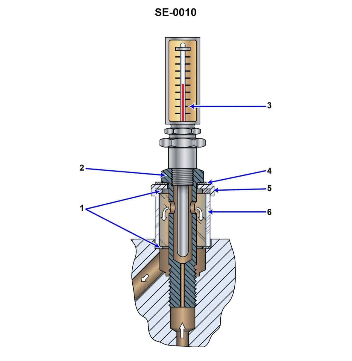
Question: What statement is true concerning the illustrated steam turbine bearing lubricating oil flow and temperature indicating device? Illustration SE-0010
A. The thermometer indicates the temperature of the oil leaving the bearing and the sight glass indicates the flow of the oil leaving the bearing as well.
B. The thermometer indicates the temperature of the oil entering the bearing and the sight glass indicates the flow of the oil entering the bearing as well.
C. The thermometer indicates the temperature of the oil entering the bearing and the sight glass indicates the flow of the oil leaving the bearing.
D. The thermometer indicates the temperature of the oil leaving the bearing and the sight glass indicates the flow of the oil entering the bearing.
The correct answer is A. The thermometer indicates the temperature of the oil leaving the bearing, and the sight glass indicates the flow of the oil leaving the bearing as well. This is because the purpose of the lubricating oil flow and temperature indicating device is to monitor the condition of the oil after it has passed through the bearing, providing information about the oil's temperature and flow rate as it exits the bearing. The other options are incorrect because they do not accurately describe the purpose and function of the components shown in the illustration. The thermometer and sight glass are specifically designed to monitor the oil as it leaves the bearing, not as it enters.
Question 40
Question: According to the illustrated lubricating oil system diagram, which of the labeled items would be used to verify that the gravity lube oil tank is full and overflowing? Illustration SE-0011
A. D
B. N
C. O
D. The gravity tank does not ordinarily overflow.
The correct answer is A. The gravity lube oil tank is designed to maintain a constant level of oil in the system. The item labeled "D" in the diagram would be used to verify that the gravity tank is full and overflowing, as it represents the overflow pipe that allows excess oil to return to the sump or drain tank. The other answer choices are incorrect - item "N" is likely the drain valve, and item "O" is likely the filling port. The gravity tank is not designed to normally overflow, so option D is also incorrect.
Question 41
Question: According to the illustrated lubricating oil system diagram, which of the labeled items is the lube oil renovating tank? Illustration SE-0011
A. A
B. B
C. C
D. K
The correct answer is A. The lube oil renovating tank is labeled as item A in the illustrated lubricating oil system diagram SE-0011. This is the correct answer based on the information provided in the diagram. The other answer choices are incorrect because: B, C, and K are labeled as different components of the lubricating oil system, such as the lube oil filter, lube oil cooler, and lube oil pump, respectively. The diagram clearly identifies the lube oil renovating tank as item A.
Question 42
Question: According to the illustrated lubricating oil system diagram, which of the labeled items would be used to manually strip out the sludge from the bottom of the main lube oil sump prior to entry for cleaning? Illustration SE-0011
A. G
B. M
C. N
D. D
The correct answer is C) N. The lubricating oil system diagram indicates that item N, labeled as the "Sump Drain Valve", would be used to manually strip out the sludge from the bottom of the main lube oil sump prior to entry for cleaning. This is because the sump drain valve provides a direct access point to the bottom of the sump, allowing the sludge and contaminants to be drained out before personnel enter the sump for cleaning and inspection. The other options, A) G, B) M, and D) D, are not the correct components for this task, as they serve different functions in the lubricating oil system, such as oil filtering, pressure regulation, and supply to various engine components, rather than draining the sump.
Question 46
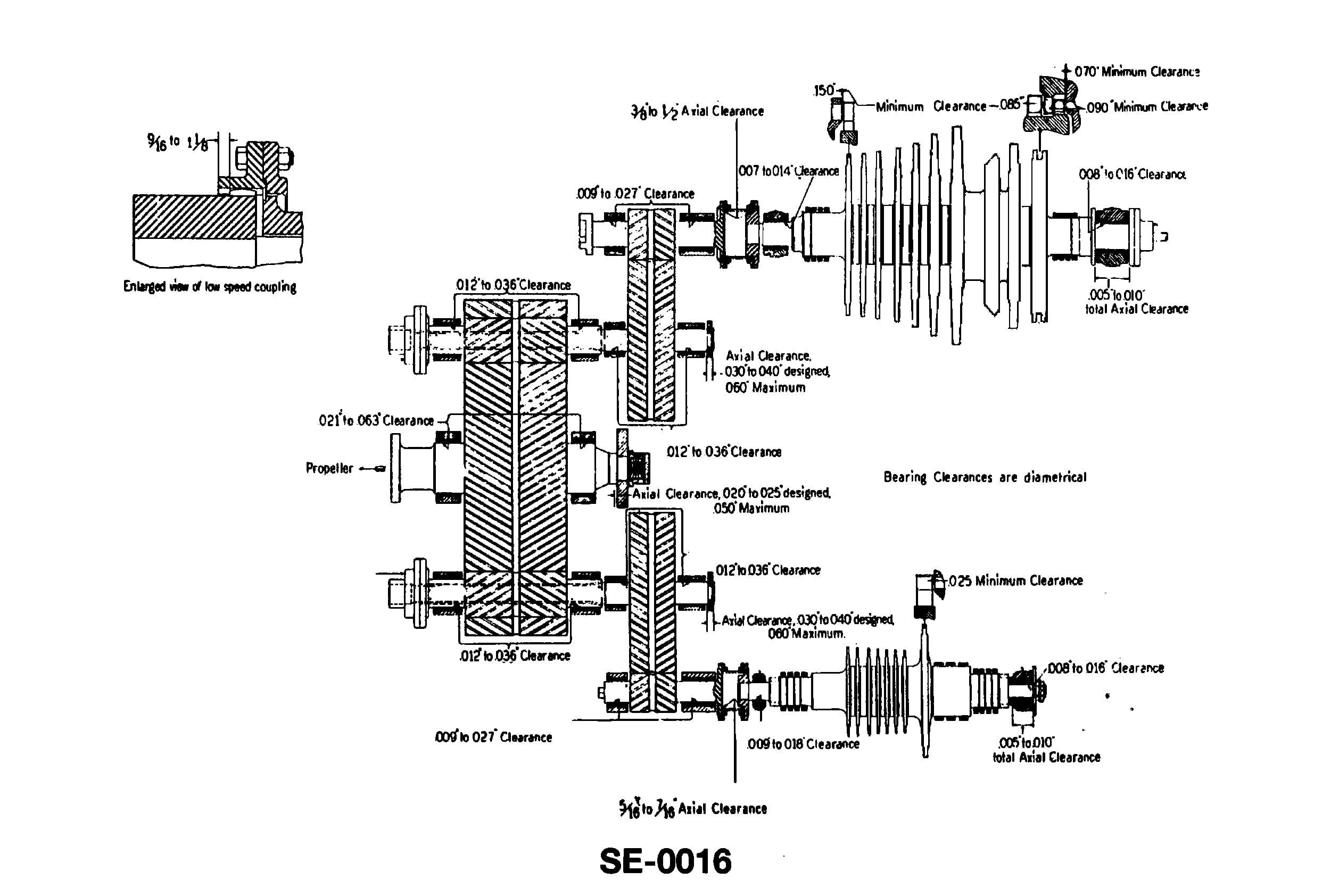
Question: According to the illustrated cross-compounded main propulsion turbine set, where are the astern elements located? Illustration SE-0016
A. Aft end of the high pressure turbine.
B. Aft end of the low pressure turbine
C. Forward end of the high pressure turbine.
D. Forward end of the low pressure turbine.
The correct answer is D) Forward end of the low pressure turbine. The astern elements in a cross-compounded main propulsion turbine set are located at the forward end of the low pressure turbine. This is because the astern elements are responsible for providing reverse thrust, and by placing them at the forward end of the low pressure turbine, they can efficiently generate the necessary reverse power. The other answer choices are incorrect because the high pressure turbine is not involved in generating astern thrust, and the aft end of the turbines would not be the appropriate location for the astern elements.
Question 52
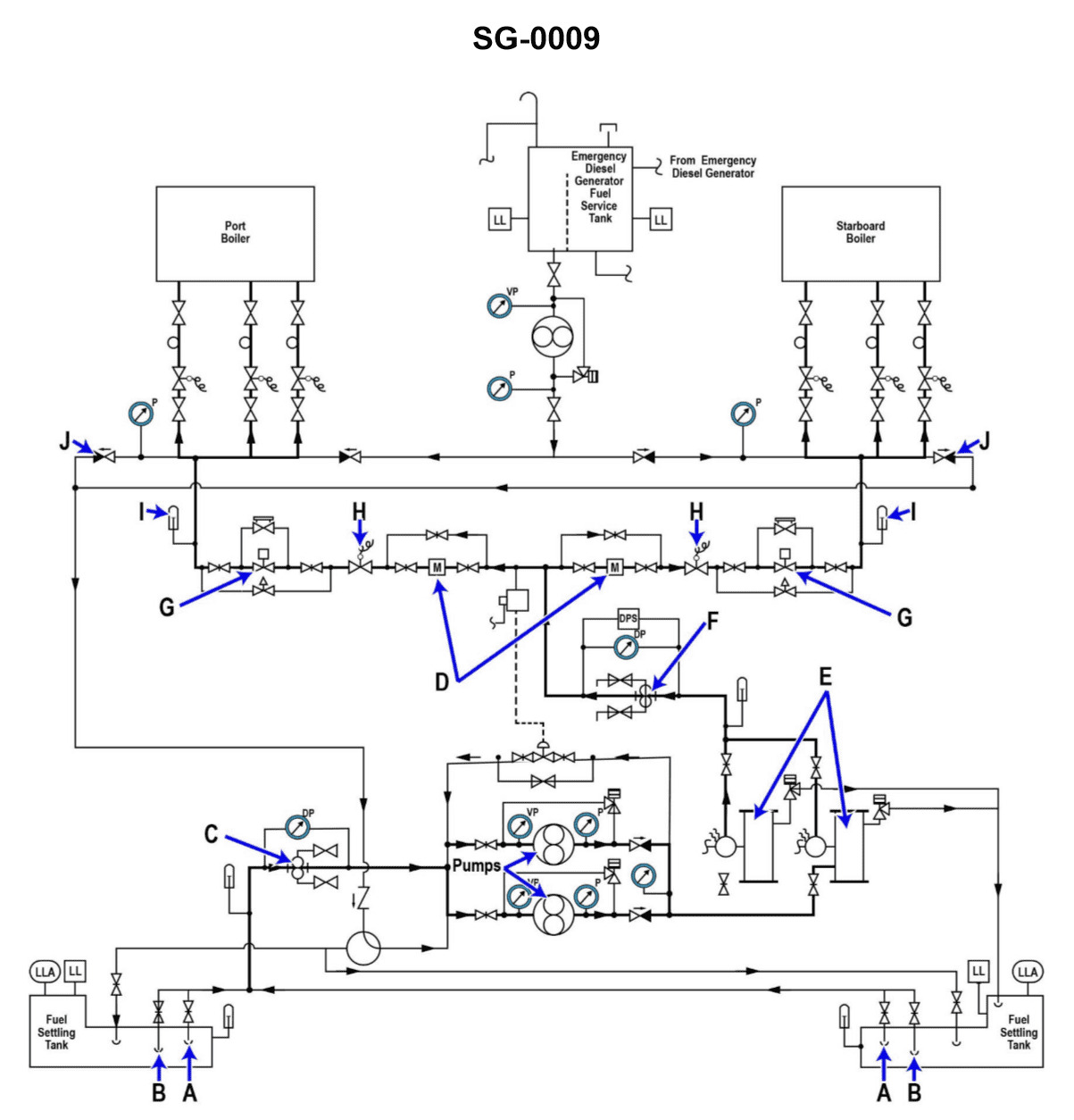
Question: Why are two fuel oil heaters "E" provided in the fuel oil system shown in the illustration? Illustration SG-0009
A. To allow fuel of different temperatures to be provided to be provided to each boiler.
B. Two heaters are necessary when both boilers steam at full load.
C. To provide a backup in case one of the heaters becomes inoperable.
D. Each heater supplies fuel to a different boiler.
The correct answer is C) To provide a backup in case one of the heaters becomes inoperable. The reason this is the correct answer is that having two fuel oil heaters provides a redundancy in the system. If one of the heaters were to fail or become inoperable, the second heater would be able to maintain the necessary fuel oil temperature for the boilers, ensuring continued operation. This redundancy is an important safety feature to prevent disruptions in the fuel supply and maintain the overall reliability of the vessel's propulsion and power systems. The other options are incorrect because they do not accurately describe the purpose of having two fuel oil heaters. Providing fuel at different temperatures to each boiler (option A) is not necessary, and having two heaters to supply fuel to different boilers (option D) is also not the primary reason for the redundancy.
Question 60
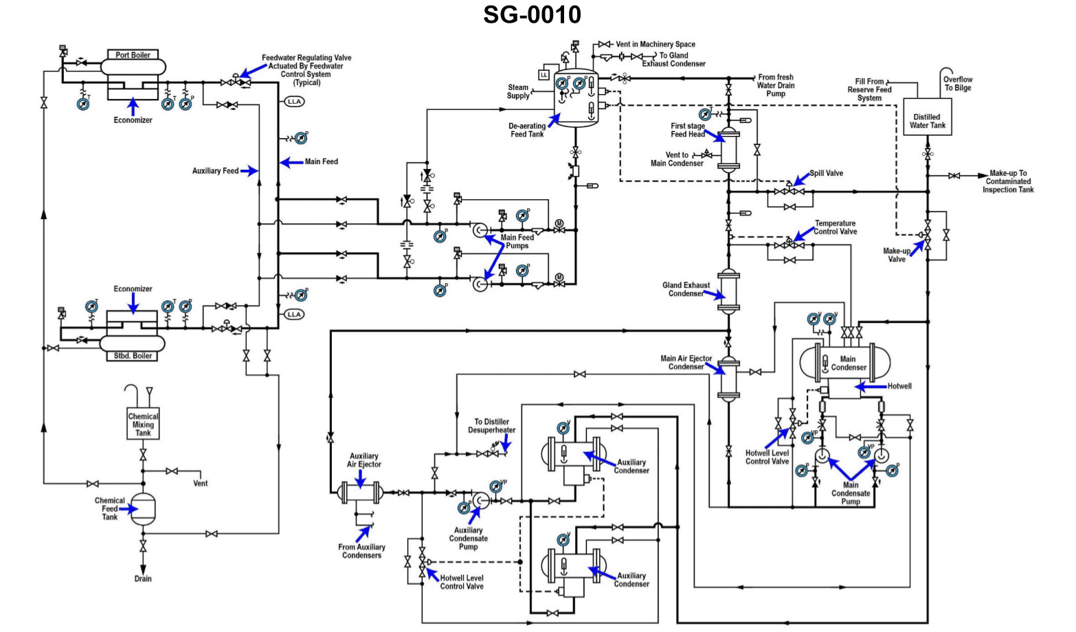
Question: According to the illustrated diagram, what is the correct sequential order of heat exchangers that the main condensate pump pumps condensate through? (SG-0010
A. A
B. B
C. C
D. D
The correct answer is B. The diagram shows the sequential order of heat exchangers that the main condensate pump pumps condensate through is B. This is the correct order based on the typical configuration of a marine steam plant, where the condensate flows from the main condenser through various heat exchangers to reheat and reuse the condensate before it is returned to the boiler. The other options are incorrect because A represents the main condenser, C represents the air ejector condenser, and D represents the gland steam condenser, which are not in the direct flow path of the main condensate pump.
Question 69
Question: According to the illustrated diagram, what statement is true concerning the operation of the main condenser hotwell level control device? Illustration SG-0010
A. The main condenser hotwell level is controlled by controlling the speed of the main condensate pump.
B. The main condenser hotwell level is controlled by throttling the flow in a recirculating line teed off the main condensate pump discharge line and leading back the main condenser.
C. The main condenser hotwell level is controlled by throttling the main condensate pump discharge to the main air ejector.
D. The main condenser hotwell level is controlled by throttling the main condensate pump suction from the main condenser hotwell.
The correct answer is B) The main condenser hotwell level is controlled by throttling the flow in a recirculating line teed off the main condensate pump discharge line and leading back the main condenser. This is the correct answer because the main condenser hotwell level is typically controlled by recirculating a portion of the main condensate pump discharge flow back to the main condenser. This allows the level in the hotwell to be maintained at the desired setpoint by adjusting the amount of recirculation flow. The other options are incorrect because they do not accurately describe how the main condenser hotwell level is typically controlled. Controlling the speed of the main condensate pump (A), throttling the discharge to the main air ejector (C), or throttling the suction from the hotwell (D) are not the primary means of controlling the hotwell level.
Question 74
Question: According to the illustrated diagram, what statement is true concerning the operation of the "make-up valve"? Illustration SG-0010
A. The "make-up valve" opens when the level in the main condenser hot well rises to a certain level and allows the excess water to be pumped to the distilled water tank by the main condensate pump.
B. The "make-up valve" opens when the level in the DFT (dearating feed tank) drops to a certain level and allows make-up water to be drawn out of the distilled water tank via vacuum drag into the main condenser.
C. The "make-up valve" opens when the level in the main condenser hot well drops to a certain level and allows make-up water to be drawn out of the distilled water tank via vacuum drag into the main condenser.
D. The "make-up valve" opens when the level in the DFT (dearating feed tank) rises to a certain level and allows the excess water to be pumped to the distilled water tank by the main condensate pump.
The correct answer is C. The "make-up valve" opens when the level in the main condenser hot well drops to a certain level and allows make-up water to be drawn out of the distilled water tank via vacuum drag into the main condenser. This is correct because the main condenser hot well is where the condensed steam from the turbine is collected. If the level in the hot well drops, the make-up valve opens to allow additional distilled water to be drawn in to maintain the proper water level in the condenser. The other options are incorrect because they do not accurately describe the function of the make-up valve in relation to the main condenser hot well level. The make-up valve does not open to pump excess water from the hot well or the deaerating feed tank to the distilled water tank.
Question 76
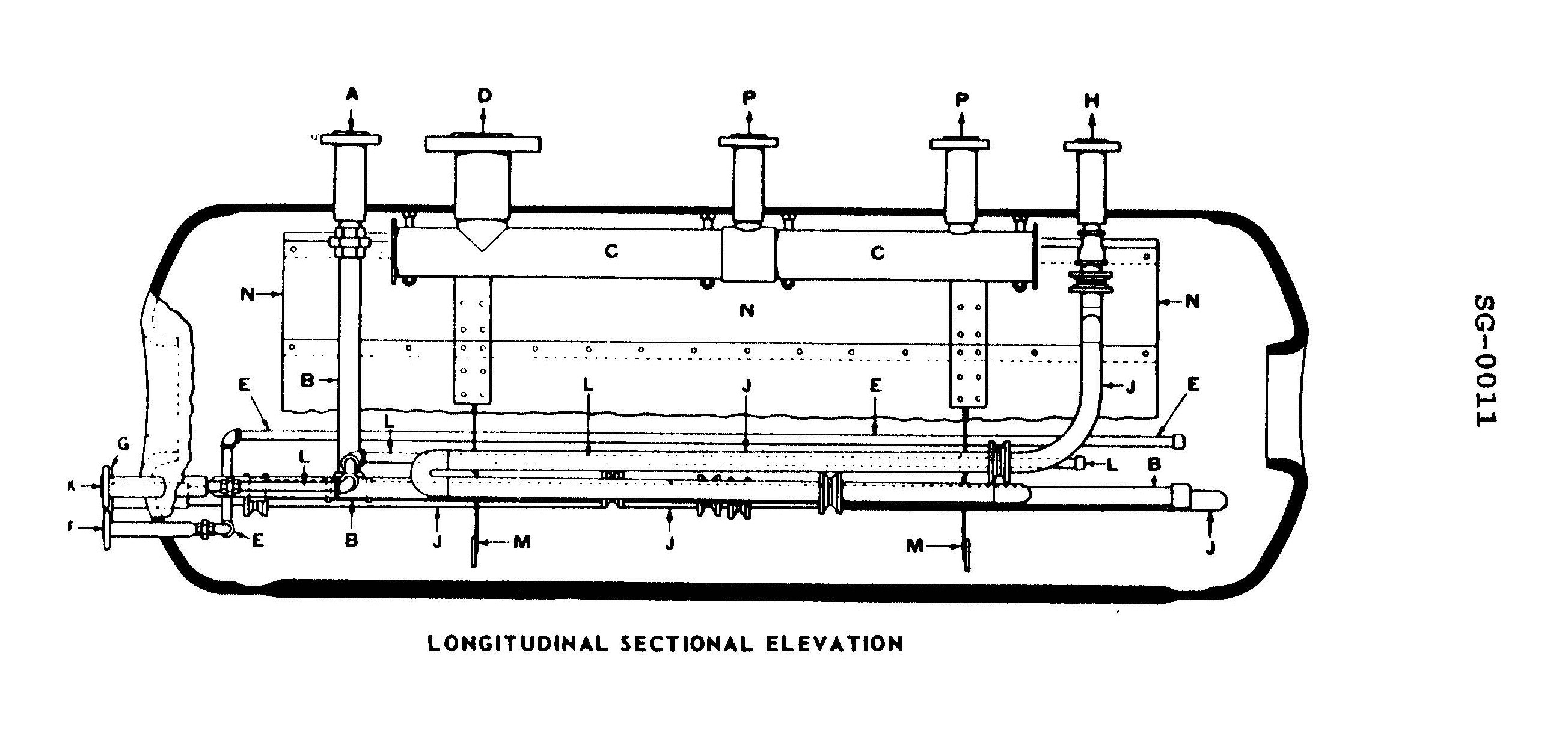
Question: Which of the labeled items within the illustrated steam drum represents the last line of defense in helping to prevent moisture carryover into the saturated steam leaving the steam drum? Illustration SG-0011
A. M
B. B
C. C
D. N
The correct answer is C. The steam drum's water level control system is the last line of defense in preventing moisture carryover into the saturated steam leaving the steam drum. The water level control system, represented by item C in the illustration, is responsible for maintaining the proper water level in the steam drum, which is crucial in preventing water droplets from being carried over into the steam supply. The other options are incorrect because they do not directly relate to controlling the water level in the steam drum. Option A (M) represents the drum's steam outlet, while options B (B) and D (N) are associated with the steam/water separation mechanisms, but do not directly control the water level.
Question 77
Question: Which of the labeled items within the illustrated steam drum represents the means by which feed water is introduced into the steam drum? Illustration SG-0011
A. B
B. E
C. J
D. L
The correct answer is A) B. The item labeled "B" in the illustration SG-0011 represents the means by which feed water is introduced into the steam drum. This is the feed water inlet, where the water to be converted into steam enters the steam drum. The other options are incorrect because: - E is the steam outlet, not the feed water inlet. - J is the water level gauge, and L is the surface blowdown, neither of which are the feed water inlet.
Question 78
Question: Which of the labeled items within the illustrated steam drum represents the means by which water treatment chemicals are introduced into the steam drum? Illustration SG-0011
A. B
B. E
C. J
D. L
The correct answer is D. The item labeled "L" in the illustration SG-0011 represents the means by which water treatment chemicals are introduced into the steam drum. This is because the steam drum is where water treatment chemicals are typically injected to maintain proper water chemistry and prevent scale buildup, corrosion, and other issues in the boiler system. The other options (B, E, and J) do not represent the chemical injection point, as they likely serve other functions such as water level indication, steam outlet, or other components of the steam drum assembly.
Question 79
Question: Which of the labeled items within the illustrated steam drum helps prevent surging of water within the drum as a vessel pitches? Illustration SG-0011
A. C
B. L
C. M
D. N
The correct answer is C) M. The item labeled M in the illustration SG-0011 represents a baffle plate. Baffle plates inside the steam drum help prevent surging of water within the drum as the vessel pitches. The baffle plate creates a more stable water level by restricting the movement of the water, reducing the risk of water carryover into the steam lines. The other options, C) C, L, and N, represent different components of the steam drum, such as the water level gauge, steam outlet, and water inlet, but they do not directly contribute to preventing water surging as the vessel moves.
Question 80
Question: Which of the labeled items within the illustrated steam drum represents the means by which floating impurities are removed from the steam drum? Illustration SG-0011
A. B
B. E
C. J
D. L
The correct answer is B) E. The item labeled E in the illustration SG-0011 represents the steam drum's skimmer, which is the means by which floating impurities are removed from the steam drum. The skimmer allows the removal of any oil, grease, or other floating contaminants from the surface of the water in the steam drum, helping to maintain the purity of the steam produced. The other options, B, J, and L, represent different components of the steam drum system, such as the water level gauge, the steam outlet, and the water inlet, respectively, but they do not directly address the removal of floating impurities.
Question 81
Question: Which of the labeled items attached to the top of the illustrated steam drum represents the means by which saturated steam is delivered to the superheater? Illustration SG-0011
A. A
B. H
C. P
D. D
The correct answer is D. The illustrated steam drum in the image SG-0011 shows the saturated steam from the boiler drum being delivered to the superheater via the labeled item D. This is the correct path for the saturated steam to enter the superheater, where it will be heated to a higher temperature and become superheated steam. The other options (A, H, and P) represent different components of the steam drum or boiler system, but do not represent the means by which saturated steam is delivered to the superheater.
Question 83
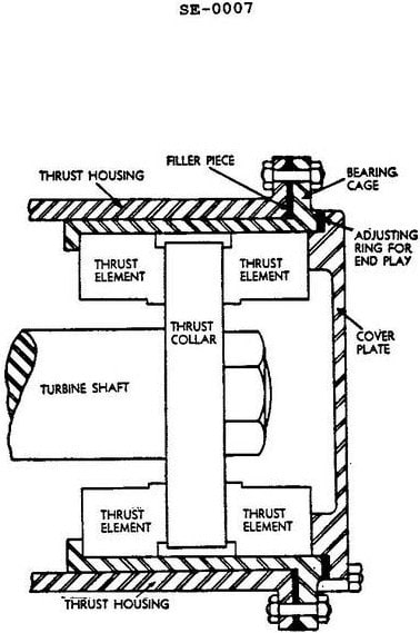
Question: What type of thrust is the bearing shown in the illustrated steam turbine shaft bearing designed to absorb? Illustration SE-0007
A. Combination of radial and axial thrust
B. Radial thrust only
C. Axial thrust only
D. Perpendicular thrust only
The correct answer is C) Axial thrust only. The steam turbine shaft bearing illustrated in SE-0007 is designed to absorb axial thrust, which is the force acting along the longitudinal axis of the shaft. This type of bearing is commonly used in steam turbine applications to support the axial movement of the rotating shaft as it is driven by the steam. The other options are incorrect because this bearing is not designed to handle radial thrust (force perpendicular to the shaft) or a combination of radial and axial thrust. Its primary function is to counteract the axial forces generated by the steam turbine's operation.
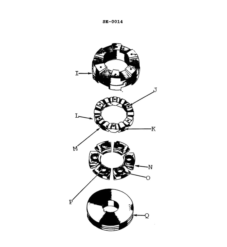
Question 84
Question: In the illustrated exploded view of a pivoted shoe thrust bearing, identify the base ring. Illustration SE-0014
A. I
B. Q
C. N
D. L
The correct answer is A) I, which represents the base ring in the illustrated exploded view of a pivoted shoe thrust bearing, SE-0014. The base ring is the stationary outer component that provides the foundation for the thrust bearing assembly. It is the fixed ring upon which the pivoted shoes and other moving components of the thrust bearing are mounted. This identification aligns with the standard conventions used in engineering diagrams and technical illustrations to label the key parts of a thrust bearing assembly. The other options (B, C, D) do not correspond to the base ring in this particular illustration and are therefore incorrect.
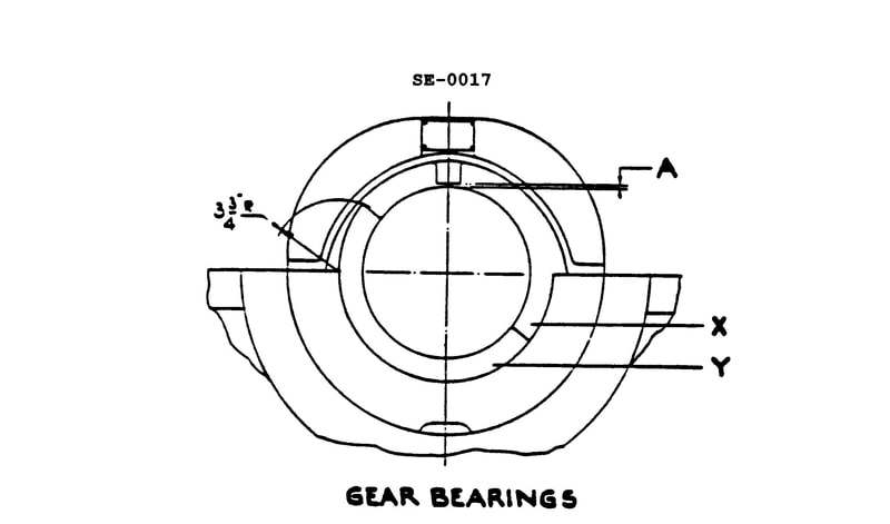
Question 85
Question: What type of bearing is shown in the illustration? Illustration SE-0017
A. Single piece bushing
B. Precision insert, split-half journal bearing
C. Tilting pad journal bearing
D. Precision-insert, split-half thrust bearing
The correct answer is B) Precision insert, split-half journal bearing. This type of bearing is commonly used in marine applications, such as those found on vessels operated by the US Coast Guard. A precision insert, split-half journal bearing consists of two halves that surround the shaft, with a precision-machined insert lining the bearing surface. This design allows for easy installation and maintenance, while providing a durable and reliable bearing solution. The other answer choices are incorrect because: A) a single piece bushing is a simpler design without the split-half construction, C) a tilting pad journal bearing has a different internal mechanism, and D) a precision-insert, split-half thrust bearing is designed to handle axial loads, rather than radial loads like a journal bearing.
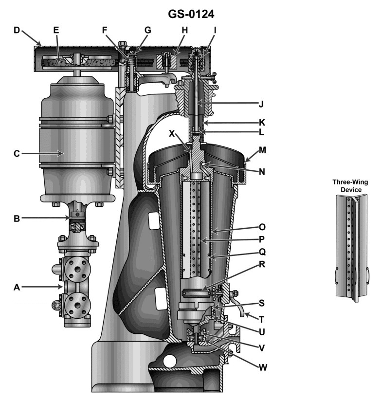
Question 96
Question: The item shown in the illustration is commonly identified as a GS-0124
A. bowl type purifier
B. machine shop lathe attachment
C. machine shop milling machine attachment
D. disk type purifier
The correct answer is A) bowl type purifier. A bowl type purifier is a common piece of equipment used on ships, including those operated by the US Coast Guard. It is used to separate contaminants from lubricating oil or fuel oil, helping to maintain the integrity of these critical systems. The GS-0124 classification refers to the general service equipment category for this type of purifier. The other options are incorrect as they describe different types of machinery or equipment not specifically related to the purification of liquids on ships.
Question 104
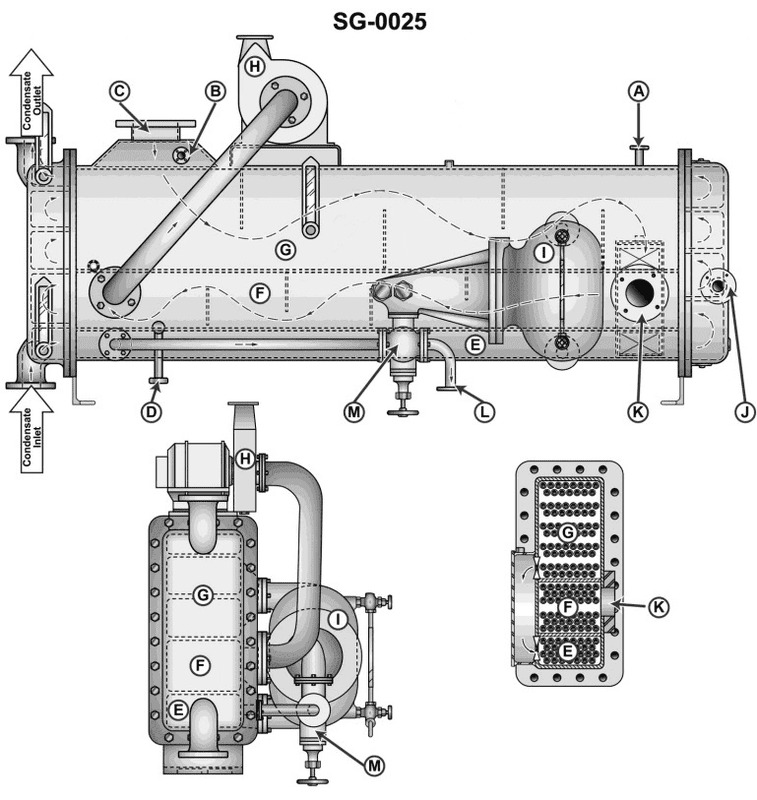
Question: The connections labeled "A" in the illustration, are used to SG-0025
A. provide a point of admission for the steam air heater drains
B. drain condensate from the feed water heater to the main condenser
C. provide a point of admission for the L.P. bleed steam
D. maintain a vacuum in the shell of the feed water heater
The correct answer is D) maintain a vacuum in the shell of the feed water heater. The connections labeled "A" in the illustration are used to maintain a vacuum in the shell of the feed water heater. This is necessary to improve the efficiency of the heat transfer process and prevent the formation of air pockets that could impede the flow of water through the heater. The other options are incorrect because they do not accurately describe the purpose of the "A" connections. Option A is for the steam air heater drains, option B is for the condensate from the feed water heater, and option C is for the low-pressure bleed steam, none of which are the correct function of the "A" connections shown in the illustration.
Question 106
Question: Under normal conditions, the rate of heat transfer in a feed water heater is most greatly affected by the _______________.
A. speed of the main feed pump
B. density of the feed water
C. temperature differential between the steam and feed water
D. pH of the feed water
The correct answer is C) temperature differential between the steam and feed water. The rate of heat transfer in a feed water heater is most greatly affected by the temperature differential between the steam and the feed water. This is because heat transfer is driven by the temperature difference, with a greater temperature difference resulting in a higher rate of heat transfer. The other factors, such as pump speed, water density, and pH, while important, do not have as significant an impact on the overall heat transfer rate in the feed water heater.
Question 107
Question: A slight vacuum is maintained in the shell of the first stage heater shown in the illustration. The primary reason for the vacuum is to __ _. Illustration SG-0025
A. force the use of the main condenser as the drain cooler
B. provide a low pressure area to guarantee feed water flow to the heater
C. maintain a positive flow of steam as supplied by the main engine LP bleed system
D. avoid the necessity of having to use the condensate pumps
The correct answer is C) maintain a positive flow of steam as supplied by the main engine LP bleed system. The primary reason for maintaining a slight vacuum in the shell of the first stage heater is to ensure a positive flow of steam from the main engine's low-pressure (LP) bleed system. This vacuum creates a lower pressure area within the heater, which helps draw the steam into the heater and facilitates the heat transfer process. The other options are incorrect because they do not directly address the purpose of the vacuum. Option A is incorrect as the vacuum is not used to force the use of the main condenser as the drain cooler. Option B is incorrect as the vacuum is not specifically to provide a low-pressure area to guarantee feed water flow to the heater. Option D is incorrect as the vacuum is not used to avoid the necessity of using the condensate pumps.
Question 108
Question: The upper section of the feed water heater indicated by "G" in the illustration is used as the _. Illustration SG-0025
A. after condenser
B. first stage heater
C. gland exhaust condenser
D. drain cooler
The correct answer is B) first stage heater. The upper section of the feed water heater indicated by "G" in the illustration SG-0025 is used as the first stage heater. This is because the feed water heater is typically a multi-stage device that uses the waste heat from various parts of the steam system to preheat the feed water before it enters the boiler. The first stage heater is the initial step in this preheating process, raising the temperature of the feed water before it undergoes further heating in subsequent stages. The other options are incorrect because they do not accurately describe the function of the component indicated by "G" in the illustration. The feed water heater is not an after condenser, a gland exhaust condenser, or a drain cooler.
Question 109
Question: The unit shown in the illustration is used as the _______________. Illustration SG-0025
A. flash evaporator salt water feed heater
B. combined low pressure feed heater
C. Butterworth feed heater
D. high pressure feed heater
The correct answer is B) combined low pressure feed heater. The illustration SG-0025 shows a component that is used as a combined low pressure feed heater in a steam propulsion system. This type of heater is used to increase the temperature of the feed water before it enters the boiler, improving the overall efficiency of the system. The other options are incorrect because: A) a flash evaporator salt water feed heater is used to produce fresh water from seawater, C) a Butterworth feed heater is a specific type of low pressure feed heater, and D) a high pressure feed heater operates at a higher pressure than the combined low pressure feed heater shown in the illustration.
Question 119
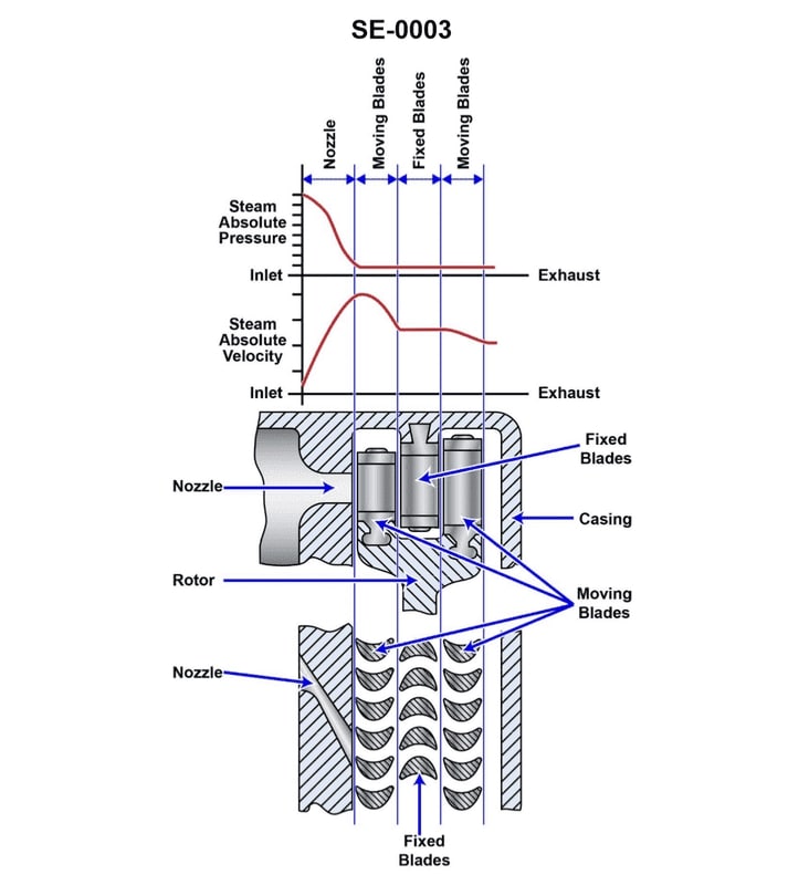
Question: What is the purpose of the items labeled "moving blades" located on the illustrated steam turbine? Illustration SE-0003
A. Convert the kinetic energy of the steam exiting the nozzle to mechanical energy of rotation.
B. Convert the potential energy of the steam exiting the nozzle to mechanical energy of rotation.
C. Change the direction of travel of the steam.
D. Convert the kinetic energy of the steam exiting the nozzle to potential energy.
The correct answer is A) Convert the kinetic energy of the steam exiting the nozzle to mechanical energy of rotation. The moving blades on a steam turbine are designed to capture the high-velocity steam exiting the turbine nozzles and convert that kinetic energy into mechanical rotation of the turbine shaft. As the steam flows over the curved surfaces of the moving blades, it causes the blades and the attached shaft to spin, generating the mechanical power that can then be used to drive other machinery. The other answer choices are incorrect because they do not accurately describe the primary function of the moving blades. Options B and D are incorrect as the blades do not convert potential energy or change the direction of the steam flow, but rather harness the kinetic energy. Option C is incorrect as the nozzles, not the moving blades, are responsible for changing the direction of the steam.
Question 122
Question: What is the purpose of the item labeled "nozzle" located on the illustrated steam turbine? Illustration SE-0003
A. Convert the potential energy of the supply steam to mechanical energy.
B. Convert the potential energy of the supply steam to kinetic energy.
C. Convert the kinetic energy of the supply steam to potential energy.
D. Convert the kinetic energy of the supply steam to mechanical energy.
The correct answer is B) Convert the potential energy of the supply steam to kinetic energy. The nozzle on a steam turbine is designed to convert the potential energy of the supply steam into kinetic energy. As the steam passes through the nozzle, its pressure decreases and its velocity increases, generating kinetic energy that can then be used to spin the turbine blades and produce mechanical power. The other answer choices are incorrect because they do not accurately describe the function of the nozzle. Option A is incorrect because the nozzle does not directly convert the steam's potential energy into mechanical energy. Options C and D are incorrect because the nozzle is not designed to convert kinetic energy back into potential energy or mechanical energy, respectively.
Question 128
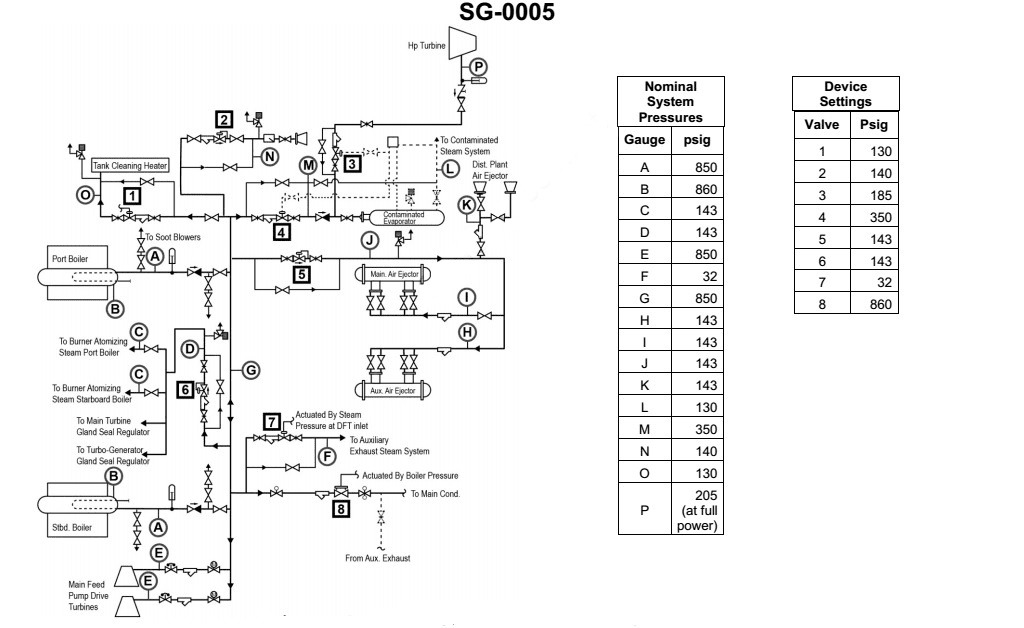
Question: According to the illustrated auxiliary steam and HP bleed steam system diagram, what are the characteristics of the steam supplied to the main feed pump drive turbines? Illustration SG-0005
A. 143 psig desuperheated steam
B. 850 psig saturated steam
C. 850 psig desuperheated steam
D. 850 psig superheated steam
The correct answer is C) 850 psig desuperheated steam. The steam supplied to the main feed pump drive turbines is desuperheated, meaning that the steam has been cooled to a temperature below its superheated state, but is still at a pressure of 850 psig. This is evident from the system diagram SG-0005, which shows the steam line from the HP bleed supplying the feed pump turbines. The other options are incorrect because A) 143 psig desuperheated steam is too low in pressure, B) 850 psig saturated steam is not desuperheated, and D) 850 psig superheated steam is hotter than the desuperheated condition shown in the diagram.
Question 133
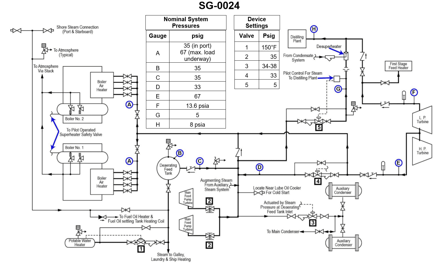
Question: According to the illustrated diagram, what is the normal source of heat for the first stage feed heater and the distilling plants when the vessel is underway under full power? Illustration SG-0024
A. Dearating feed tank.
B. Main feed pump drive turbine exhaust.
C. Intermediate pressure bleed steam.
D. Low pressure bleed steam.
The correct answer is D) Low pressure bleed steam. The first stage feed heater and the distilling plants on a vessel typically use low pressure bleed steam as the normal source of heat when the vessel is underway under full power. This is because the low pressure bleed steam from the main turbine provides a readily available source of heat that can be efficiently utilized to preheat the feed water before it enters the boiler, as well as to provide heat for the distilling plants that produce fresh water. The other options are incorrect because: A) the deaerating feed tank is not a source of heat, B) the main feed pump drive turbine exhaust is a higher pressure steam source, and C) the intermediate pressure bleed steam would be at a higher pressure than the low pressure bleed steam that is the normal source of heat for these components.
Question 135
Question: The auxiliary exhaust system shown in the illustration can be supplied by steam from the . SG-0024
A. distilling plant
B. turbo generators
C. IP bleed system
D. LP bleed system
You are correct, the answer is C) IP bleed system. The auxiliary exhaust system shown in the illustration can be supplied by steam from the IP (Intermediate Pressure) bleed system. This is because the IP bleed system taps into the steam turbine at an intermediate pressure point, providing a source of high-pressure steam that can be used to power the auxiliary exhaust system. The other options are incorrect because the distilling plant (A) and the turbo generators (B) are not directly connected to the steam supply for the auxiliary exhaust system, and the LP (Low Pressure) bleed system (D) would not provide the necessary high-pressure steam required for the auxiliary exhaust system.
Question 136
Question: The intermediate pressure bleed steam system, shown in the illustration, is used to supply steam at approximately . SG-0024
A. 13.6 psia
B. 13.6 psig
C. 35.0 psig
D. 67.0 psig
The correct answer is D) 67.0 psig. The intermediate pressure bleed steam system is used to supply steam at approximately 67.0 psig. This is a typical pressure for intermediate pressure bleed steam, which is extracted from the steam turbine at an intermediate stage and used for various heating and other purposes on the ship. The other answer choices are incorrect because 13.6 psia and 13.6 psig are too low for an intermediate pressure steam system, while 35.0 psig is generally too low for this application.
Question 137
Question: According to the illustrated diagram, what is the normal source of heat for the boiler air heaters when the vessel is underway under full power? Illustration SG-0024
A. Intermediate pressure bleed steam.
B. Main feed pump drive turbine exhaust.
C. Dearating feed tank.
D. Main boiler furnace.
The correct answer is A) Intermediate pressure bleed steam. When a vessel is underway under full power, the boiler air heaters are typically heated by intermediate pressure bleed steam. This steam is extracted from the intermediate stage of the main steam turbine, providing a reliable and efficient source of heat for the air heaters. The intermediate pressure bleed steam is readily available and can be easily directed to the air heaters to preheat the combustion air, improving the overall efficiency of the boiler system. The other options are incorrect because they do not represent the normal source of heat for the boiler air heaters when the vessel is underway under full power. The main feed pump drive turbine exhaust (B) is not the primary source of heat, the dearating feed tank (C) does not directly provide heat to the air heaters, and the main boiler furnace (D) is not the normal source of heat for the air heaters.
Question 172
Question: According to the illustrated auxiliary steam and HP bleed system diagram, what steam loads are supplied by the same steam pressure reducing station? Illustration SG-0005
A. Contaminated evaporator and distilling plant air ejectors
B. Tank cleaning heater and ship's whistle
C. Main feed pump drive turbines and turbine gland seal regulators
D. Main boiler burner steam atomizers and turbine gland seal regulators
The correct answer is D) Main boiler burner steam atomizers and turbine gland seal regulators. This is correct because the illustrated auxiliary steam and HP bleed system diagram shows that the same steam pressure reducing station supplies steam to both the main boiler burner steam atomizers and the turbine gland seal regulators. The diagram clearly indicates these two steam loads are connected to the same pressure reducing station. The other options are incorrect because they do not accurately reflect the connections shown in the diagram. For example, the contaminated evaporator and distilling plant air ejectors, as well as the tank cleaning heater and ship's whistle, are not supplied by the same pressure reducing station as the main boiler burner steam atomizers and turbine gland seal regulators.
Question 173
Question: According to the illustrated steam and HP bleed system diagram, which steam pressure reducing station has the lowest set point? Illustration SG-0005
A. Tank cleaning seawater heater
B. Main boiler burner steam atomizers and turbine gland seal regulators
C. Main, auxiliary, and distilling plant air ejectors
D. Ship's whistle
The correct answer is A) Tank cleaning seawater heater. The tank cleaning seawater heater would have the lowest set point pressure among the options provided, as it requires the least amount of steam pressure to operate effectively. The other options, such as the main boiler burner steam atomizers, turbine gland seal regulators, and air ejectors, typically require higher steam pressures to function properly. The ship's whistle does not directly rely on the steam pressure reducing system, so it is not the correct answer.