Pass Your Coast Guard Licensing Exams!
Study offline, track your progress, and simulate real exams with the Coast Guard Exams app
Steam Plants - Assistant
75 images
Question 6
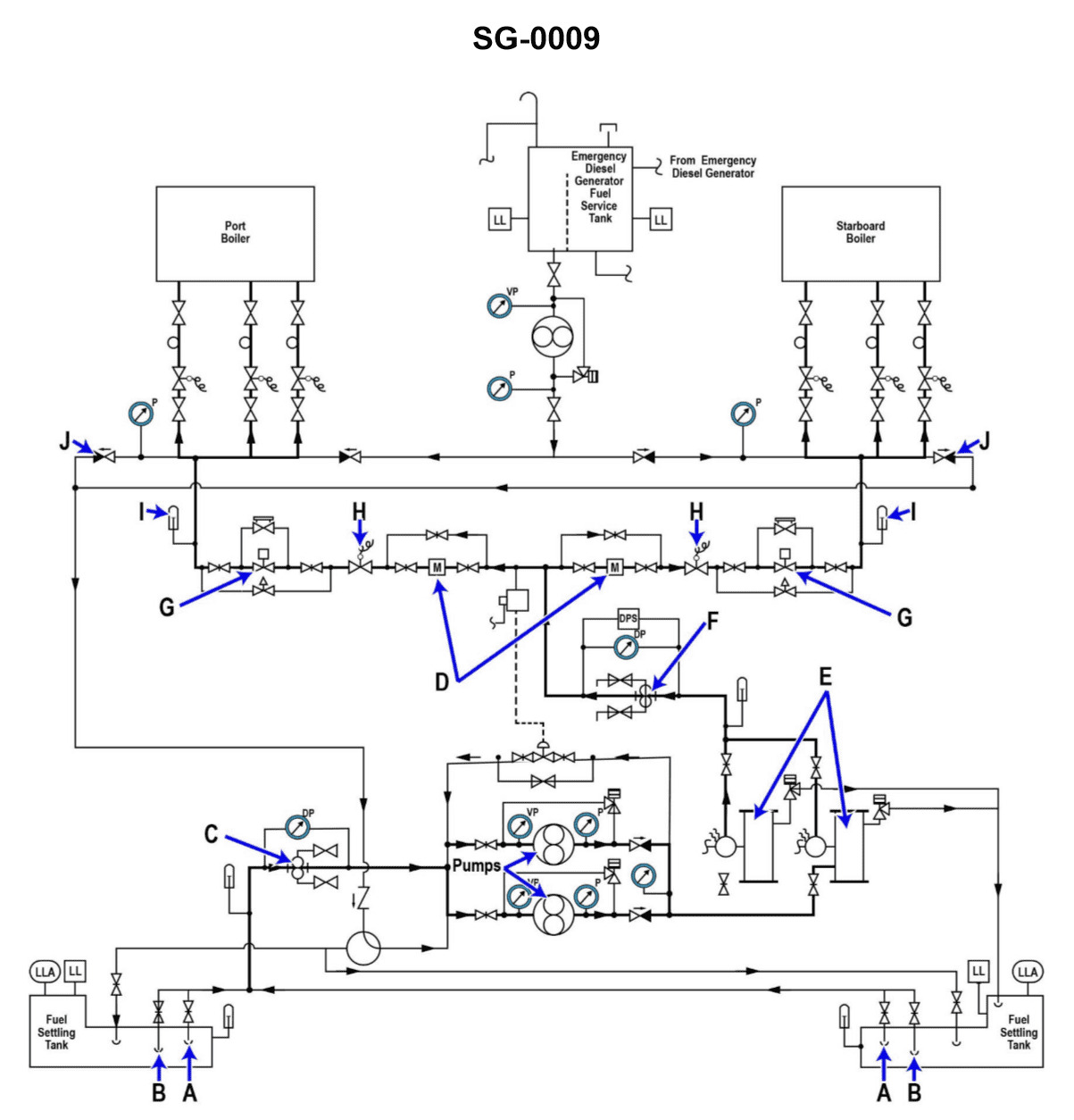
Question: Valve "H" shown in the illustration, functions to _. Illustration SG-0009
A. prevent a backflow from the manifold
B. recirculate fuel oil during start-up
C. regulate the amount of fuel burned
D. provide a quick shut off of fuel to the boiler
The correct answer is D) provide a quick shut off of fuel to the boiler. Valve "H" in the illustration is a fuel shut-off valve, which functions to quickly stop the flow of fuel to the boiler in case of an emergency or malfunction. This is an important safety feature to prevent potential fire or explosion hazards. The other answer choices are incorrect because they do not accurately describe the primary function of this particular valve. Valve "H" is not primarily used for preventing backflow, recirculating fuel during start-up, or regulating the amount of fuel burned.
Question 29
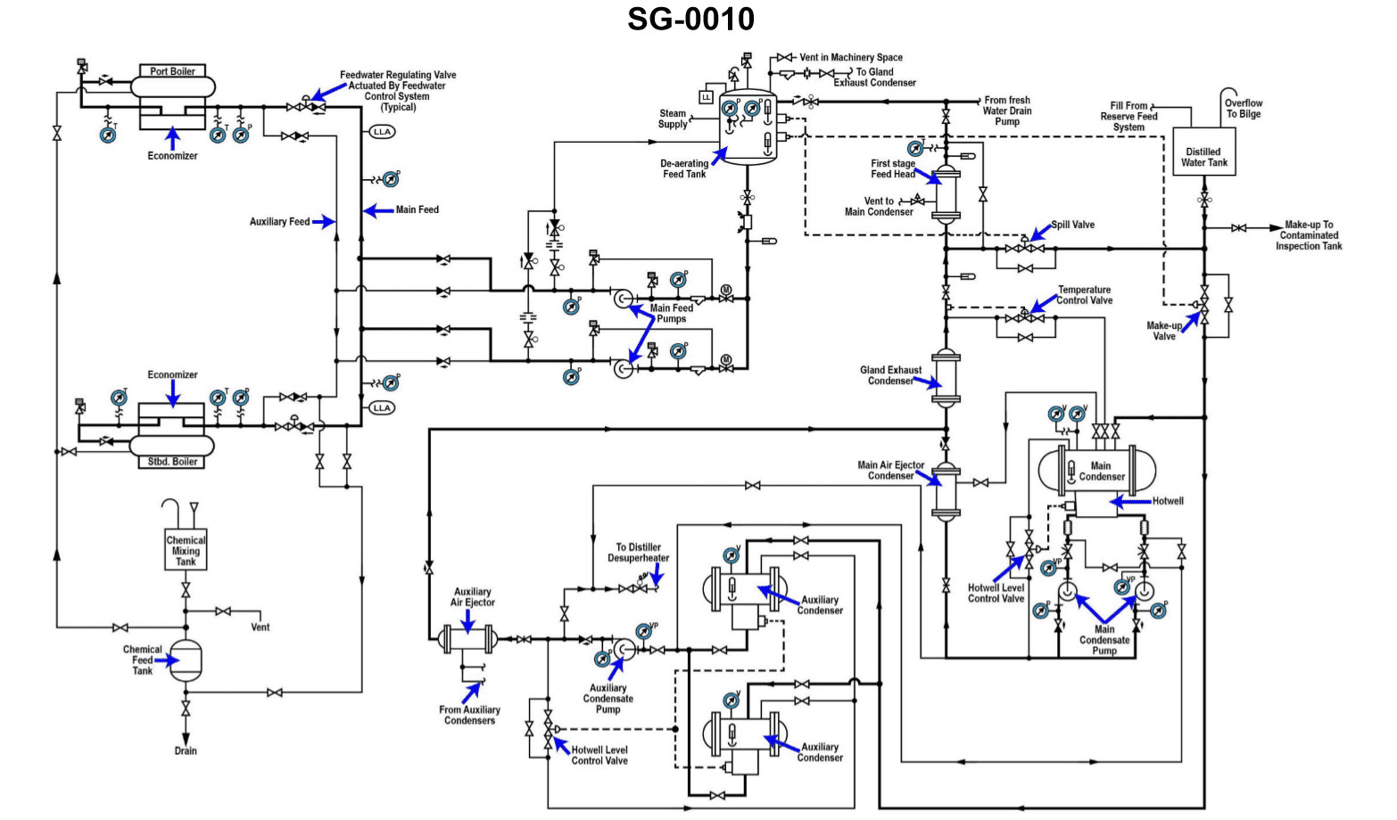
Question: Which piping system is described in the illustration provided? Illustration SG-0010
A. Auxiliary desuperheated steam system
B. Main superheated steam system
C. Turbine bleed steam system
D. Boiler feed and condensate system
The correct answer is D) Boiler feed and condensate system. This is the correct answer because the illustration SG-0010 depicts a typical boiler feed and condensate system, which is an essential piping system found on vessels. This system is responsible for delivering treated water from the condenser back to the boiler, completing the closed-loop cycle for steam generation. The other options are incorrect because they describe different steam systems not shown in the provided illustration. Option A refers to an auxiliary desuperheated steam system, Option B describes a main superheated steam system, and Option C is a turbine bleed steam system, none of which are depicted in the given illustration.
Question 30
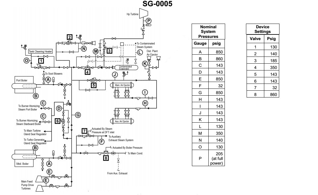
Question: In the system illustrated the valves at point "A" are _ . Illustration SG-0005
A. swing check/stop valves
B. globe valves/gate valves
C. stop-check/stop valves
D. gauge valves/drain valves
The correct answer is C) stop-check/stop valves. The valves at point "A" in the system illustrated in SG-0005 are stop-check/stop valves. These types of valves are commonly used in marine applications to control the flow of fluids and provide a means of isolating equipment for maintenance or emergency purposes. Stop-check/stop valves combine the functions of a stop valve (which can be opened and closed to control flow) and a check valve (which allows flow in only one direction), making them a versatile choice for many marine systems. The other answer choices are incorrect because they do not accurately describe the type of valves depicted in the illustration. Swing check/stop valves, globe valves/gate valves, and gauge valves/drain valves have different functionalities and are not the specific type of valves used at point "A" in the SG-0005 system.
Question 44
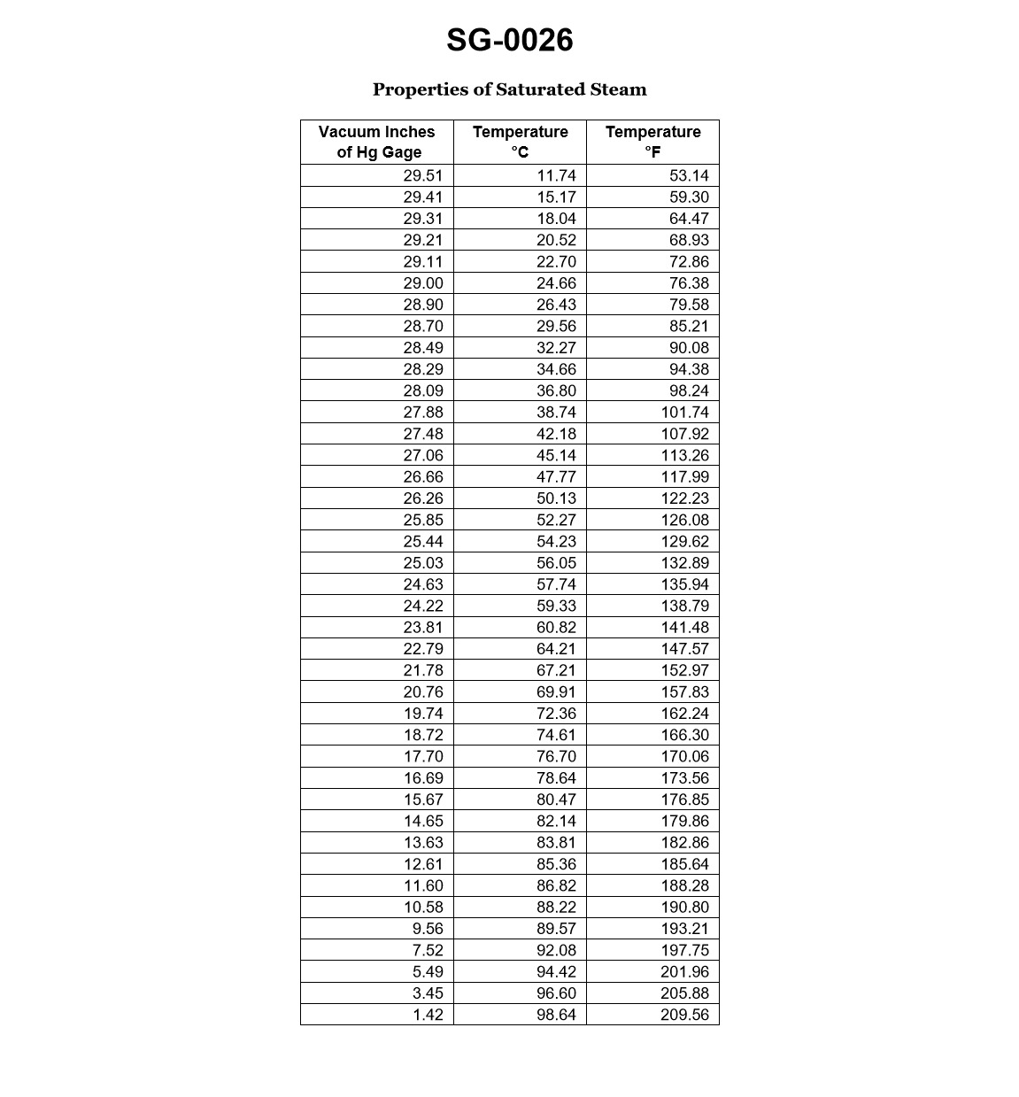
Question: If the main condenser were operating at a vacuum of 28.5" Hg, a condensate discharge temperature of 86°F, a sea water inlet temperature of 72°F, and a sea water outlet temperature of 79°F, what would be the condensate depression? Illustration SG-0026
A. 0.2 inches Hg
B. 0.7 inches Hg
C. 4 degrees Fahrenheit
D. 7 degrees Fahrenheit
The correct answer is C) 4 degrees Fahrenheit. The condensate depression is the difference between the temperature of the condensate discharge and the saturation temperature corresponding to the main condenser vacuum. With a vacuum of 28.5" Hg, the saturation temperature would be around 92°F. Since the condensate discharge temperature is 86°F, the condensate depression is 92°F - 86°F = 4 degrees Fahrenheit. The other options are incorrect because A) 0.2 inches Hg is the incorrect unit, B) 0.7 inches Hg is not the correct value, and D) 7 degrees Fahrenheit is not the correct temperature difference.
Question 59
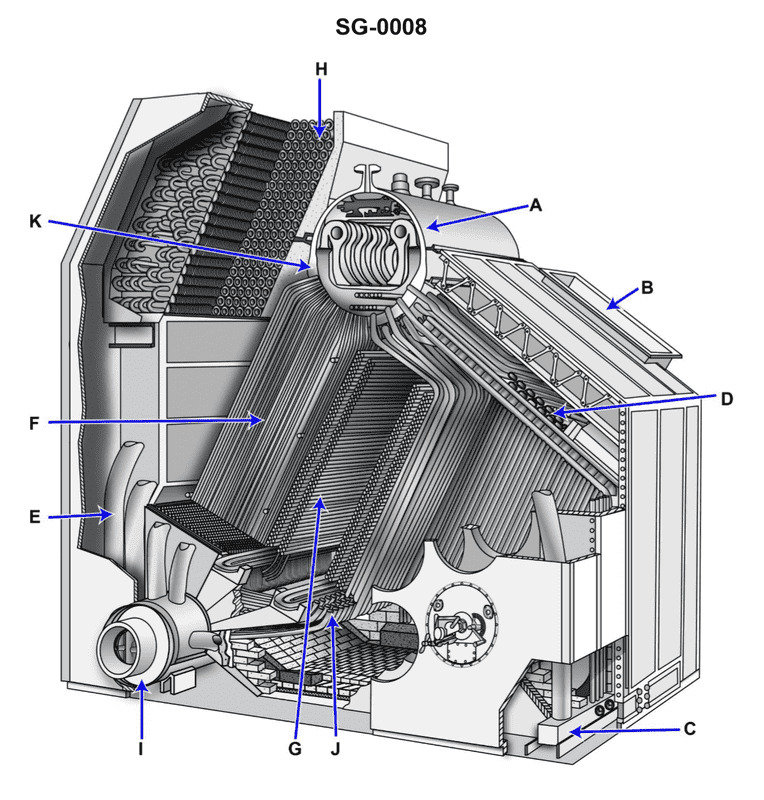
Question: Arrow "B" shown in the illustration indicates the _. Illustration SG-0008
A. retractable soot blower opening
B. uptakes
C. combustion air inlet
D. regenerative air heater
The correct answer is C) combustion air inlet. The illustration SG-0008 is depicting a typical marine boiler system. Arrow "B" points to the opening where combustion air enters the boiler to support the burning of fuel. This is the combustion air inlet, which is the correct answer. The other answer choices are incorrect because they do not accurately describe the component indicated by Arrow "B" in the illustration. A retractable soot blower, uptakes, and a regenerative air heater are different parts of a boiler system, but they are not what Arrow "B" is pointing to in this specific illustration.
Question 76
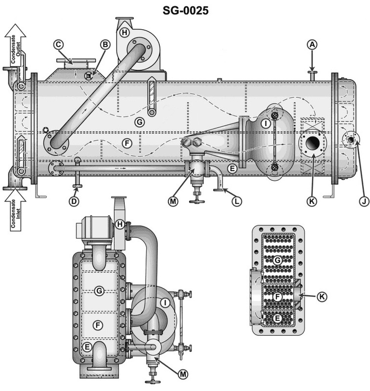
Question: The feed water heater shown in the illustration was designed to maintain the required feed water outlet temperature with an approximate 10" (25.4 cm) Hg shell vacuum. If the shell vacuum is increased to approximately 16" (40.64 cm) Hg vacuum, the_______________ Illustration SG-0025
A. flow rate of condensate to the feed heater will increase
B. overall plant operating efficiency will increase
C. vacuum in the main condenser will drop as the feed heater shell vacuum increases
D. feed water outlet temperature will decrease
The correct answer is D) the feed water outlet temperature will decrease. Explanation: When the shell vacuum of the feed water heater is increased from 10" Hg to 16" Hg, the lower pressure in the shell will result in a lower saturation temperature of the steam inside the heater. This lower steam temperature will, in turn, result in a lower feed water outlet temperature, as the heat transfer from the steam to the feed water will be reduced. The increased shell vacuum does not affect the flow rate of condensate or the overall plant efficiency, and it will not impact the vacuum in the main condenser.
Question 124
Question: The boiler shown in the illustration has its screen tubes connecting the steam drum and the component labeled ' '. Illustration SG-0008
A. I
B. F
C. G
D. D
The correct answer is A. The screen tubes of the boiler shown in the illustration SG-0008 connect the steam drum to the component labeled "I", which is the water drum. This is the correct configuration as per the standard design of a water-tube boiler, where the screen tubes facilitate the circulation of water and steam between the steam drum and the water drum. The other answer choices (B, C, and D) do not represent the correct component that the screen tubes connect to in this boiler configuration.
Question 131
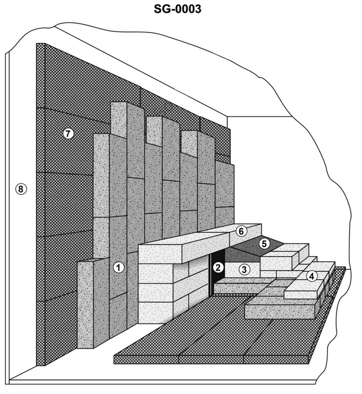
Question: According to the illustration of a typical boiler furnace rear wall, which item number would best represent "insulating brick"? Illustration SG-0003
A. 1
B. 2
C. 3
D. 7
The correct answer is A) 1, which represents "insulating brick" according to the illustration SG-0003 of a typical boiler furnace rear wall. The insulating brick is the first layer of the rear wall, designed to provide thermal insulation and protect the structural integrity of the boiler. This is a critical component to ensure the safe and efficient operation of the boiler system. The other answer choices, B) 2, C) 3, and D) 7, represent different elements of the boiler furnace rear wall, such as the refractory lining, structural steel, and the outer casing, respectively. While these components are also important, they do not directly correspond to the "insulating brick" as depicted in the illustration.
Question 150
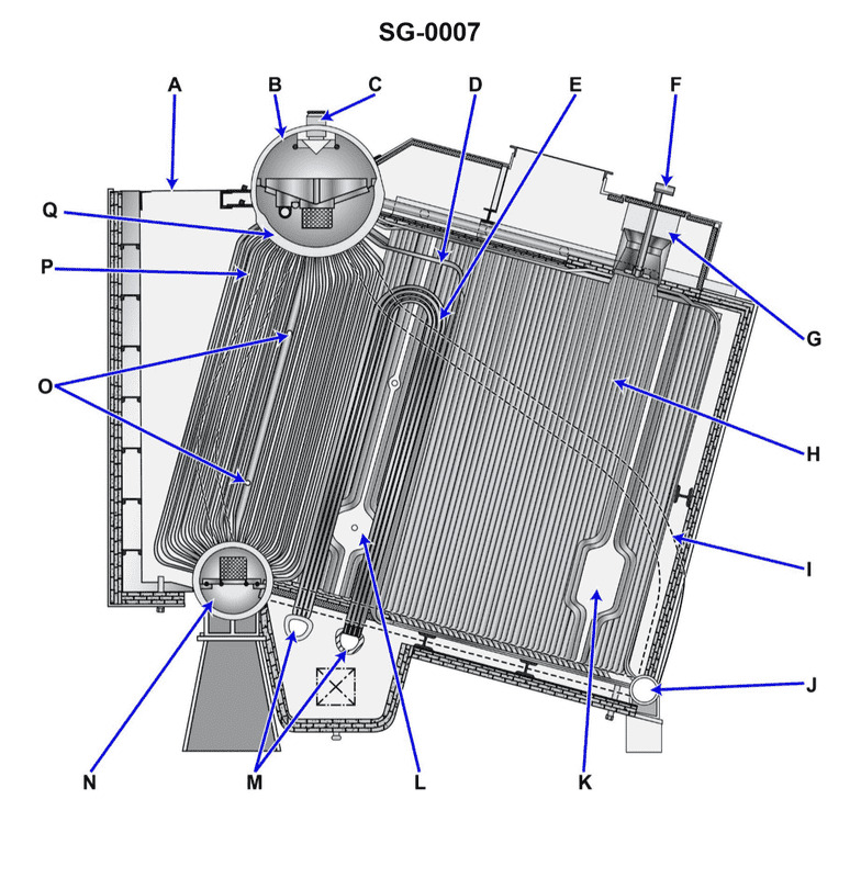
Question: The boiler shown in the illustration, arrow "O" indicates the Illustration SG-0007
A. main generating tubes
B. superheater tubes
C. screen tubes
D. soot blower elements
The correct answer is D) soot blower elements. The soot blower elements are responsible for cleaning the boiler tubes by directing high-pressure steam or air onto the tubes, dislodging any accumulated soot or debris. This is a critical function in maintaining the efficiency and proper operation of the boiler. The other options, such as main generating tubes, superheater tubes, and screen tubes, are different components of the boiler that have specific functions, but they are not indicated by the arrow "O" in the provided illustration.
Question 151
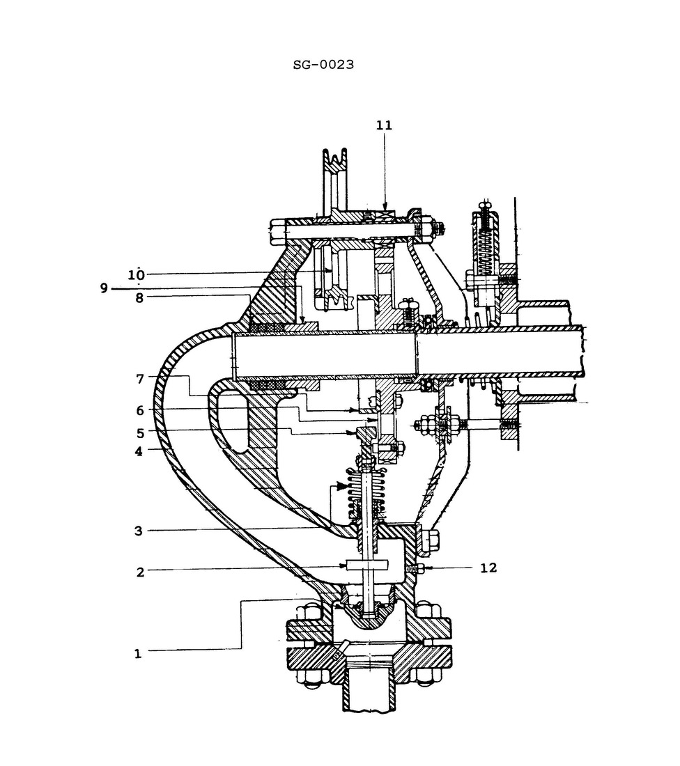
Question: The purpose of the pressure control disk installed in the multi-nozzle soot blower, as shown in the illustration, is to _______________. Illustration SG-0023
A. control the pressure exerted on the valve spring retainer
B. control the pressure exerted on the steam valve disk when the cam secures the steam supply
C. increase the pressure in the steam supply line for proper soot blower operation
D. reduce the steam supply pressure to the soot blower element
The correct answer is D) reduce the steam supply pressure to the soot blower element. The pressure control disk installed in the multi-nozzle soot blower is designed to reduce the high-pressure steam supply to a lower pressure suitable for the soot blower's operation. This helps prevent damage to the soot blower components by limiting the pressure exerted on the system. The other answer choices are incorrect because they do not accurately describe the purpose of the pressure control disk. Option A refers to controlling the pressure on the valve spring retainer, which is not the primary function of the pressure control disk. Options B and C are also incorrect, as the disk is not intended to control the pressure exerted on the steam valve disk or increase the pressure in the steam supply line.
Question 152
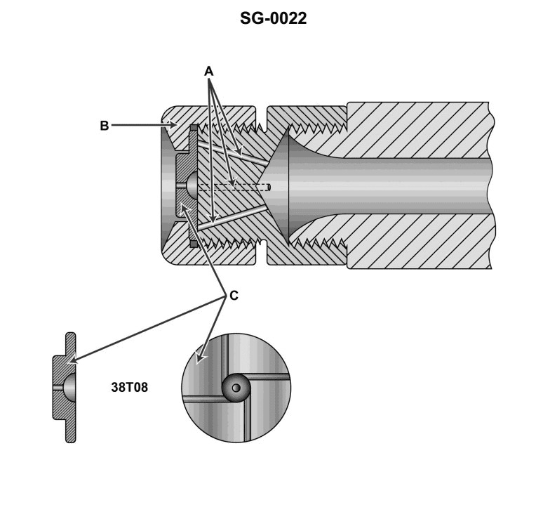
Question: The illustrated burner atomizer assembly is . Illustration SG-0022
A. used in a return flow type burner management system
B. straight mechanical
C. an example of a rotary cup type atomizer
D. used only for variable load steam atomization
The correct answer is B) straight mechanical. The illustration SG-0022 depicts a simple straight mechanical atomizer, which is a common type of atomizer used in burner systems. This type of atomizer uses the mechanical force of the fuel to break it up into a fine spray, without the need for additional pressurized air or steam. The straight mechanical design is a basic and reliable atomizer configuration, making it suitable for a variety of burner applications. The other answer choices are incorrect because: A) return flow burners use a different type of atomizer, C) rotary cup atomizers have a different internal design, and D) variable load steam atomization is a separate atomizer technology not shown in the illustration.
Question 196
Question: The items labeled "A" in the illustration are the _______________. Illustration SG-0025
A. low-pressure steam supply connections
B. high-pressure drain connections
C. low-pressure vent connections
D. low-pressure drain connections
The correct answer is C) low-pressure vent connections. The items labeled "A" in the illustration SG-0025 are the low-pressure vent connections. This is the correct answer because the low-pressure vent connections allow excess pressure in the low-pressure steam system to be safely released, preventing overpressurization. The other answer choices, such as low-pressure steam supply connections, high-pressure drain connections, and low-pressure drain connections, do not accurately describe the components labeled "A" in the given illustration.
Question 197
Question: A slight vacuum is maintained in the shell of the first stage heater shown in the illustration. The primary reason for the vacuum is to _______________. Illustration SG-0025
A. provide a low-pressure area to guarantee feed water flow to the heater
B. maintain a positive flow of steam as supplied by the main engine LP bleed system
C. avoid the necessity of having to use the condensate pumps
D. force the use of the main condenser as the drain cooler
The correct answer is B) maintain a positive flow of steam as supplied by the main engine LP bleed system. The first stage heater is typically maintained under a slight vacuum to create a low-pressure environment that allows the steam from the main engine's low-pressure bleed system to flow into the heater and transfer its heat to the feed water. This vacuum helps ensure a positive flow of steam into the heater, rather than relying on the condensate pumps to force the flow (which would be the case if there was no vacuum). The other options are incorrect because they do not accurately describe the primary reason for the vacuum in the first stage heater. Option A is incorrect as the vacuum is not primarily to guarantee feed water flow, but to enable the steam flow. Option C is incorrect as the vacuum is not to avoid the use of condensate pumps, but to facilitate the steam flow. Option D is incorrect as the vacuum is not to force the use of the main condenser as the drain cooler.
Question 198
Question: Which of the following statements is correct concerning the operation of the level or drain regulator associated with the feed water heater shown in the illustration is correct? Illustration SG-0025
A. The regulator maintains the flow of steam into the first stage heater of this unit.
B. The regulator controls the flow rate of condensate leaving the feed water outlet.
C. The regulator controls the volume of condensate leaving the gland exhaust condenser.
D. The regulator controls the level of condensate collected in the drain cooler section.
The correct answer is D) The regulator controls the level of condensate collected in the drain cooler section. The level or drain regulator associated with the feed water heater is responsible for controlling the level of condensate collected in the drain cooler section. This ensures that the appropriate amount of condensate is drained from the system, maintaining the proper water level and preventing issues such as waterlogging or dry operation. The other options are incorrect because: A) The regulator does not maintain the flow of steam into the first stage heater. B) The regulator does not control the flow rate of condensate leaving the feed water outlet. C) The regulator does not control the volume of condensate leaving the gland exhaust condenser.
Question 199
Question: The connections labeled "A" in the illustration, are used to _______________. SG-0025
A. maintain a vacuum in the shell of the feed water heater
B. provide a point of admission for the steam air heater drains
C. provide a point of admission for the L.P. bleed steam
D. drain condensate from the feed water heater to the main condenser
The correct answer is A) maintain a vacuum in the shell of the feed water heater. The connections labeled "A" in the illustration are used to maintain a vacuum in the shell of the feed water heater. This is necessary to improve the efficiency of the heat transfer process, as a vacuum helps to prevent the formation of steam bubbles that could reduce the effectiveness of the heat exchange. The other answer choices are incorrect because they do not accurately describe the purpose of the "A" connections in the feed water heater system. Options B, C, and D describe different functions or connections within the overall steam or condensate system, but they are not specifically related to the vacuum maintenance in the feed water heater shell.
Question 202
Question: The unit shown in the illustration is used as the _______________. Illustration SG-0025
A. combined low-pressure feed heater
B. high-pressure feed heater
C. flash evaporator salt water feed heater
D. Butterworth feed heater
The correct answer is A) combined low-pressure feed heater. The combined low-pressure feed heater is used to heat the boiler feed water before it enters the boiler. This helps improve the overall efficiency of the steam generation system. The illustration SG-0025 shows a component that is part of the feed water heating system, and the combined low-pressure feed heater is the most appropriate description for this unit based on its function. The other options are incorrect because they describe different components of the steam generation system that are not shown in the specific illustration provided.
Question 203
Question: The feed water heater shown in the illustration is actually comprised of three separately functioning heat exchangers. These heat exchangers are identified as the _ . Illustration SG-0025
A. first-stage heater, gland exhaust condenser, and drain cooler
B. drain cooler, distillate condenser, and fresh water drain collector
C. inter condenser, after condenser, and gland exhaust condenser
D. first-stage heater, inter condenser, and after condenser
The correct answer is A) first-stage heater, gland exhaust condenser, and drain cooler. The feed water heater shown in the illustration is comprised of three separately functioning heat exchangers: the first-stage heater, the gland exhaust condenser, and the drain cooler. This is the correct identification of the three components that make up the feed water heater system. The other answer choices are incorrect because they do not accurately describe the three components of the feed water heater system as depicted in the illustration SG-0025. Options B, C, and D list different combinations of heat exchangers that do not match the specific components of the feed water heater shown in the illustration.
Question 204
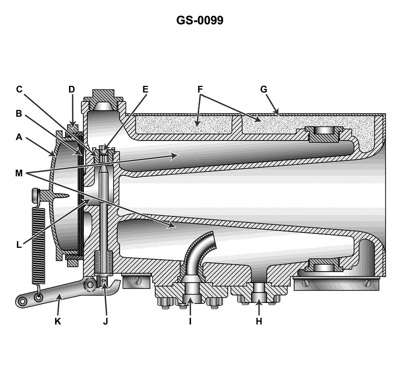
Question: The function of item "E" shown in the illustration is to_______________ Illustration 0099 . Illustration GS-0099
A. allow steam/condensate or air to be evacuated from the unit as sound is produced
B. act as a reed to enable the production of sound
C. pulse supply steam or air to chamber "M"
D. control the admission of steam into chamber "L" as part of the process to produce sound
The correct answer is D) control the admission of steam into chamber "L" as part of the process to produce sound. The function of item "E" in the illustration is to control the admission of steam into chamber "L". This is a critical part of the process to produce sound, as the steam entering chamber "L" is what enables the sound generation mechanism to operate. The other answer choices do not accurately describe the function of this component in the sound production process.
Question 208
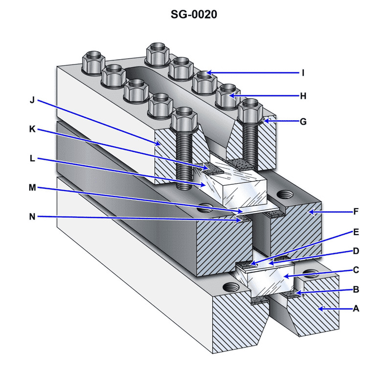
Question: The items labeled "D" and "M" as indicated on the illustration are commonly called _______________. Illustration SG-0020
A. cork gaskets
B. glass inserts
C. face plates
D. mica sheets
The correct answer is D) mica sheets. Mica sheets are the items commonly labeled as "D" and "M" on the illustration SG-0020. Mica is a naturally occurring mineral that is often used in electrical equipment due to its insulating properties. In the context of a US Coast Guard Captain's License Examination, mica sheets are typically used as insulating materials in various electrical components and devices found on vessels. The other answer choices are incorrect because cork gaskets, glass inserts, and face plates do not typically have the same insulating function as mica sheets in electrical equipment on ships.
Question 215
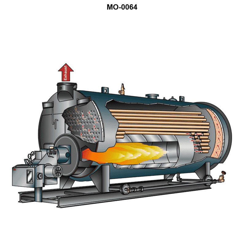
Question: The boiler shown in the illustration would be classed as________________. Illustration MO-0064
A. forced circulation, coil-type
B. two-pass, scotch marine
C. two-pass, water-tube
D. single-pass, fire-tube, scotch marine
The correct answer is D) single-pass, fire-tube, scotch marine. The illustration MO-0064 depicts a single-pass, fire-tube, scotch marine boiler. This type of boiler is characterized by the hot gases from the fire passing through the boiler tubes, heating the water surrounding the tubes in a single pass, before exiting the boiler. This design is commonly found on smaller vessels and is classified as a fire-tube boiler. The other options are incorrect because forced circulation, coil-type boilers have a different design, two-pass, scotch marine boilers have a different flow pattern, and two-pass, water-tube boilers use a different construction method.
Question 232
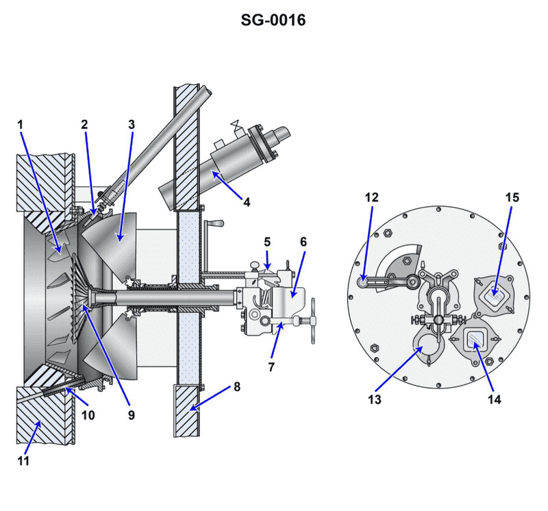
Question: According to the illustration, what part number identifies the "air doors"? Illustration SG-0016
A. 1
B. 3
C. 9
D. 4
The correct answer is B) 3, which identifies the "air doors" in the illustration SG-0016. The illustration is a diagram of a vessel, and the numbered callouts correspond to various parts of the ship. In this case, the number 3 is pointed to the "air doors," which are the openings that allow air to flow into or out of the vessel's interior spaces. The other answer choices are incorrect because they do not correspond to the part that identifies the "air doors" in the given illustration.
Question 234
Question: According to the illustration, what part number identifies the "air door handle"? Illustration SG-0016
A. 4
B. 6
C. 7
D. 12
The correct answer is D) 12. According to the illustration SG-0016, the "air door handle" is identified as part number 12. This can be clearly seen in the labeled diagram. The other answer choices are incorrect because: A) 4 is the number for the "air vent", not the air door handle. B) 6 is the number for the "handhold", not the air door handle. C) 7 is the number for the "hatch", not the air door handle.
Question 237
Question: According to the illustration, what part number identifies the "igniter"? Illustration SG-0016
A. 2
B. 3
C. 7
D. 9
A) 2 is the correct answer. The illustration SG-0016 clearly labels part number 2 as the "igniter". The other answer choices do not correspond to the "igniter" label on the diagram. The correct identification of the igniter component is important for understanding the operation and maintenance of the equipment depicted in the illustration, which is relevant knowledge for those seeking a US Coast Guard Captain's License.
Question 238
Question: According to the illustration, what part number identifies the "diffuser"? Illustration SG-0016
A. 1
B. 3
C. 9
D. 7
The correct answer is C) 9, which identifies the "diffuser" in the illustration SG-0016. This is because the illustration clearly labels part number 9 as the "diffuser," indicating that this component is the diffuser as per the diagram. The other answer choices do not correspond to the part labeled as the diffuser. The other options are incorrect because they do not match the part number assigned to the diffuser in the given illustration.
Question 244
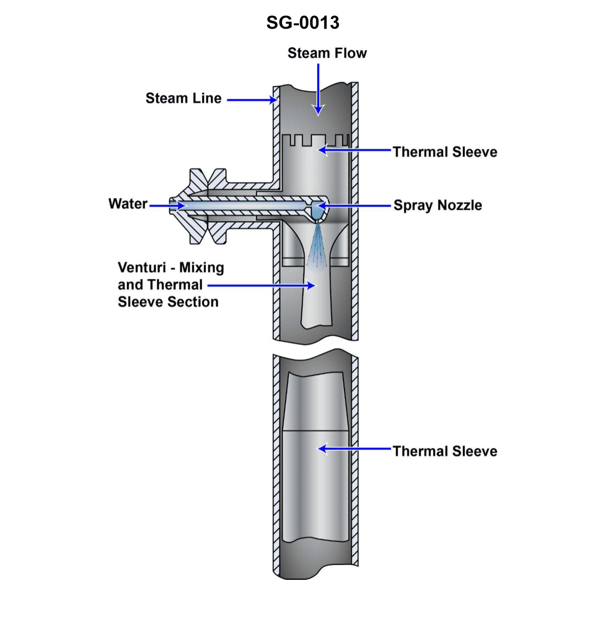
Question: The device shown in the illustration is a/an _______________. Illustration SG-0013
A. air ejector
B. desuperheater
C. deaerator
D. eductor
The correct answer is B) desuperheater. A desuperheater is a device used to lower the temperature of superheated steam, which is steam at a temperature higher than the saturation temperature corresponding to its pressure. The illustration SG-0013 depicts a desuperheater, which is the correct identification of the device shown. The other answer choices are incorrect. An air ejector is a device used to create a vacuum, a deaerator is used to remove dissolved gases from feedwater, and an eductor is a type of jet pump. None of these devices match the functionality and appearance of the component shown in the illustration.
Question 246
Question: According to the data given in illustration, which of the following would be the physical state of the fluid at a gage vacuum of 28.09 inches Hg, and 117.99 degrees Fahrenheit? Illustration SG-0026
A. Sub cooled liquid.
B. Saturated liquid.
C. Superheated vapor.
D. Mixture of saturated liquid and vapor.
The correct answer is C) Superheated vapor. At a gage vacuum of 28.09 inches Hg and a temperature of 117.99 degrees Fahrenheit, the fluid would be in a superheated vapor state. This is because the given conditions place the fluid above the saturation line on a pressure-temperature diagram, indicating that the fluid is in a superheated state. The other options are incorrect because a gage vacuum of 28.09 inches Hg corresponds to a low pressure, which would not support a sub-cooled liquid (A) or a saturated liquid (B) state. Additionally, a temperature of 117.99 degrees Fahrenheit is too high for a mixture of saturated liquid and vapor (D) to exist at the given pressure.
Question 247
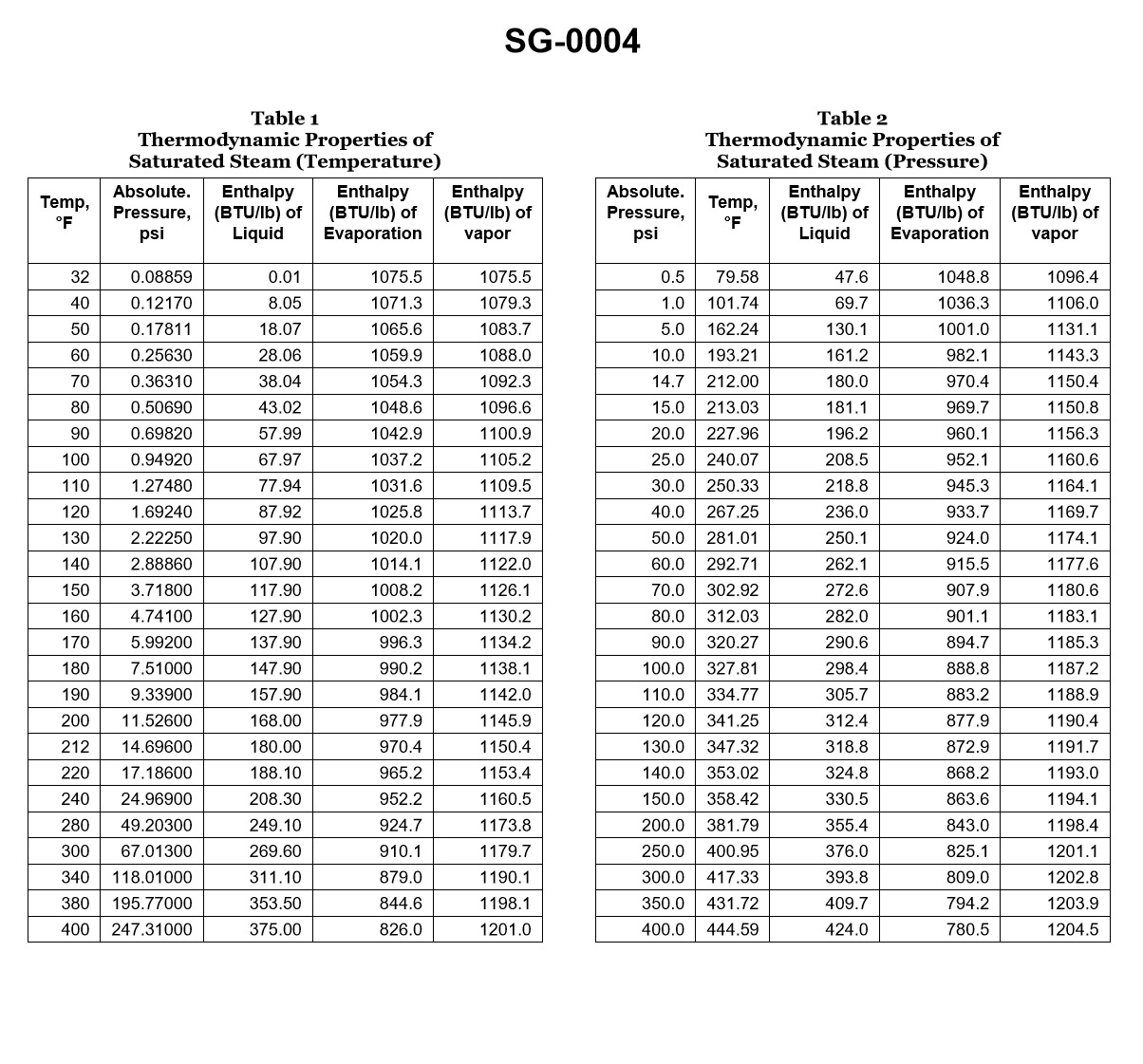
Question: With reference to the chart, if a boiler generates saturated steam at 385.3 psig, how much heat per pound was required to change the water into steam if the feed water temperature was initially 104.5°C? Illustration SG-0004
A. 96.85 BTU
B. 97.15 BTU
C. 1016.40 BTU
D. 1196.45 BTU
The correct answer is C) 1016.40 BTU. To determine the heat required to change the water into steam, we need to calculate the enthalpy of vaporization (latent heat) at the given pressure of 385.3 psig. At this pressure, the saturated steam temperature is approximately 435°F (223.9°C). Using steam tables or appropriate thermodynamic calculations, the enthalpy of vaporization at this temperature is approximately 1016.40 BTU/lb. This is the amount of heat required to change the water into steam, given the initial feed water temperature of 104.5°C. The other options are incorrect because they do not accurately represent the enthalpy of vaporization at the specified pressure and temperature conditions.
Question 248
Question: According to the data given in the illustration, which of the following would be the physical state of the fluid at a gage vacuum of 29.00 inches Hg, and 85.21 degrees Fahrenheit? Illustration SG-0026
A. Sub cooled liquid.
B. Saturated liquid.
C. Superheated vapor.
D. Mixture of saturated liquid and vapor.
The correct answer is C) Superheated vapor. At a gage vacuum of 29.00 inches Hg and a temperature of 85.21 degrees Fahrenheit, the fluid would be in a superheated vapor state. This is because the temperature and pressure conditions are above the saturation point of the fluid, meaning the fluid is in a superheated state and not a saturated liquid or a mixture of liquid and vapor. The other options are incorrect because a gage vacuum of 29.00 inches Hg would not result in a subcooled liquid (A) or a saturated liquid (B), and the temperature and pressure conditions are not within the two-phase region, ruling out a mixture of saturated liquid and vapor (D).
Question 251
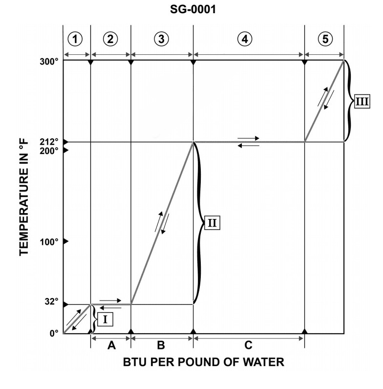
Question: With an increase in the saturation pressure of a fluid, the value represented by line "5" on the graph will _______________. Illustration SG-0001
A. increase the number of BTU's per pound, per change in degree of temperature
B. decrease the number of BTU's per pound, per change in degree of temperature
C. remain virtually the same
D. represent an increase in the latent heat of condensation
The correct answer is C) remain virtually the same. The saturation pressure of a fluid is the pressure at which the fluid transitions from a liquid to a gas (or vice versa) at a given temperature. An increase in the saturation pressure does not affect the value represented by line "5" on the graph, which corresponds to the latent heat of condensation. The latent heat of condensation is a fundamental property of the fluid and remains constant regardless of changes in saturation pressure. The other options are incorrect because they do not accurately describe the effect of increased saturation pressure on the latent heat of condensation.
Question 302
Question: Which of the devices listed is indicated by arrow "H" shown in the illustration? Illustration SG-0008
A. Overdeck superheater
B. Economizer
C. Air heater
D. Steam soot blowers
The correct answer is B) Economizer. The economizer is a heat exchanger that preheats the boiler feedwater before it enters the boiler. This improves the overall efficiency of the steam generation system. The illustration SG-0008 clearly indicates the economizer as the component labeled with the arrow "H", which matches the description of the economizer. The other answer choices are incorrect because they do not match the component labeled with arrow "H" in the illustration. The overdeck superheater, air heater, and steam soot blowers are different components of the steam generation system, but they are not the component indicated by the arrow "H" in this specific illustration.
Question 322
Question: The component labeled "F" as shown in the illustration is_______________ Illustration SG-0007
A. a permanently installed Orsat apparatus
B. one of the retractable soot blower elements
C. a regenerative air heater
D. one of the main burner assemblies
The correct answer is D) one of the main burner assemblies. The illustration SG-0007 is likely a diagram of a boiler or furnace system, and the component labeled "F" is one of the main burner assemblies that provide the primary fuel source for the system. This is the correct answer based on the typical components found in such systems. The other answer choices are incorrect because they do not match the expected components in a boiler or furnace illustration. An Orsat apparatus, soot blower elements, and a regenerative air heater are not the primary fuel sources for the system depicted in the illustration.
Question 338
Question: The boiler superheater shown in the illustration is a/an_______________ Illustration SG-0007
A. horizontal U-type
B. overdeck convection-type
C. overdeck integral-type
D. vertical U-type
The correct answer is D) vertical U-type. The vertical U-type superheater is characterized by the superheater tubes being arranged in a U-shape and oriented vertically within the boiler. This configuration is commonly used in Coast Guard-inspected vessels. The vertical orientation and U-shape allow for efficient heat transfer from the boiler's hot gases to the superheater tubes, which in turn superheats the steam. The other options are incorrect because: A) a horizontal U-type superheater has the tubes arranged in a U-shape but oriented horizontally; B) an overdeck convection-type superheater is located above the boiler deck; and C) an overdeck integral-type superheater is also located above the boiler deck, integrated with the boiler design.
Question 341
Question: Where is the superheater located in the boiler shown in the illustration? Illustration SG-0008
A. G
B. H
C. I
D. J
The correct answer is A. The superheater is located at location G in the illustration SG-0008. The superheater is a heat exchanger that superheats the steam produced in the boiler, increasing its temperature and energy content before it enters the steam turbine or other steam-powered equipment. This is a standard component in the design of boilers used for power generation. The other options (H, I, and J) in the illustration represent different components of the boiler, such as the steam drum, the water column, and the water gauge, but they do not depict the location of the superheater.
Question 342
Question: Which of the devices listed is shown in the boiler illustration? Illustration SG-0008
A. Separately fired superheater
B. Regenerative air heater
C. Integral or interdeck superheater
D. Retractable soot blower
The correct answer is C) Integral or interdeck superheater. The illustration SG-0008 shows a boiler cross-section, and an integral or interdeck superheater is the device depicted. This type of superheater is incorporated directly into the boiler design, as opposed to a separately fired superheater (option A) which is a standalone component. The illustration does not show a regenerative air heater (option B) or a retractable soot blower (option D), which are different boiler components not featured in this particular diagram.
Question 347
Question: Deaeration of condensate primarily occurs in what section of the illustration shown? Illustration SG-0010
A. main condenser hotwell
B. DFT
C. distilled water tank
D. first stage feed heater
The correct answer is B) DFT (Deaerating Feed Tank). The deaeration of condensate primarily occurs in the deaerating feed tank (DFT) section of the illustration SG-0010. The DFT is designed to remove dissolved gases, such as oxygen and carbon dioxide, from the condensate before it enters the boiler. This deaeration process helps prevent corrosion and other issues in the boiler system. The other options are incorrect because the main condenser hotwell, distilled water tank, and first stage feed heater are not the primary locations where deaeration of condensate occurs. The DFT is specifically designed and intended for this purpose.
Question 357
Question: The boiler wrapper sheet, shown in the illustration, is indicated by arrow . Illustration SG-0007
A. A
B. B
C. H
D. I
The correct answer is B. The boiler wrapper sheet, shown in the illustration SG-0007, is indicated by arrow B. The wrapper sheet is the outer shell or casing of the boiler that encloses the fire box and other internal components. It is a critical component of the boiler structure and design, providing structural integrity and containment for the high-pressure steam. The other answer choices (A, C, and D) do not correctly identify the boiler wrapper sheet as indicated by the illustration. Understanding the components of a boiler system is essential knowledge for the US Coast Guard Captain's License Examination, particularly for those operating vessels with steam propulsion.
Question 359
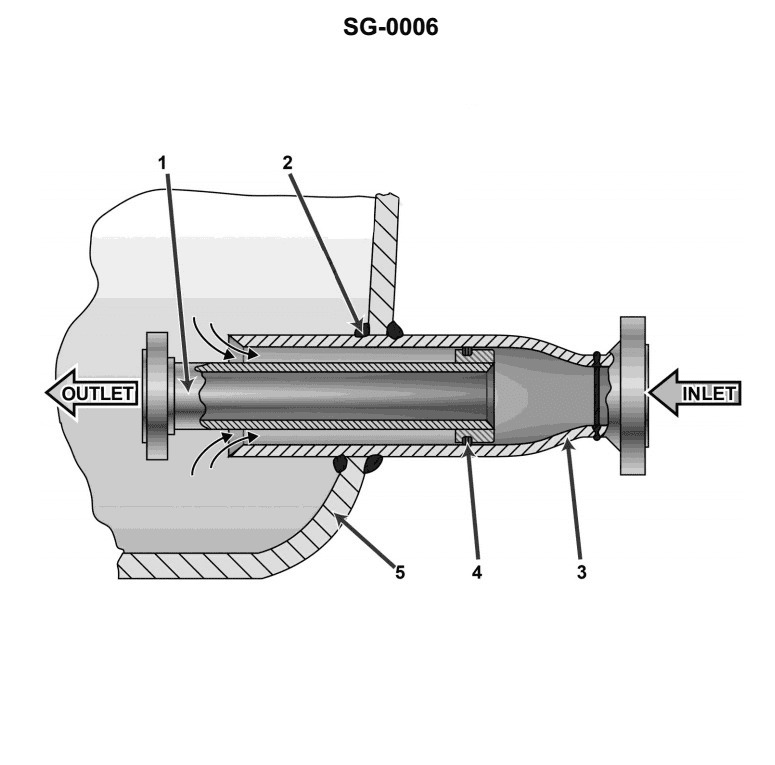
Question: The main purpose of the boiler steam drum component shown in the illustration is to _______________. Illustration SG-0006
A. reduce vibration
B. reduce the possibility of priming
C. permit expansion during pressure surges
D. prevent thermal shock
The correct answer is D) prevent thermal shock. The steam drum in a boiler serves to maintain a stable water level and prevent thermal shock to the boiler components. When water undergoes rapid heating, it can experience significant expansion which can lead to thermal stress and damage to the boiler. The steam drum helps to mitigate this by providing a volume to accommodate the expansion of the water, preventing sudden pressure surges and stabilizing the temperature of the system. The other answer choices are incorrect because they do not accurately describe the primary purpose of the steam drum. Reducing vibration, reducing priming, and permitting expansion during pressure surges are secondary functions of the steam drum, but do not represent its main purpose of preventing thermal shock to the boiler.
Question 385
Question: In the boiler shown in the illustration, the arrow "E" indicates a _______________. Illustration SG-0008
A. support tube
B. recirculating tube
C. water wall tube
D. downcomer
The correct answer is D) downcomer. In a boiler, the downcomer is a vertical pipe or tube that carries the cooler, denser water from the steam drum down to the bottom of the boiler. This water then circulates back up through the water wall tubes (indicated by "C") to the steam drum, completing the circulation loop. The downcomer is responsible for ensuring proper water flow and distribution within the boiler, which is crucial for efficient heat transfer and steam generation. The other options are incorrect because they do not accurately describe the component indicated by the arrow "E" in the given boiler illustration. Support tubes, recirculating tubes, and water wall tubes serve different functions within the boiler design.
Question 396
Question: If a boiler generates saturated steam at 125.3 psig, how much heat is required to change the water into steam if the feed water temperature is 240°F? Illustration SG-0004
A. 30.5 Btu/lb
B. 116.5 Btu/lb
C. 582.7 Btu/lb
D. 983.4 Btu/lb
The correct answer is D) 983.4 Btu/lb. To change water into saturated steam at 125.3 psig, the heat required is the latent heat of vaporization at that pressure, which is 983.4 Btu/lb. This value can be found in steam tables or other references for thermodynamic properties of steam. The other answer choices are incorrect because they do not represent the full latent heat of vaporization required to change the water at 240°F into saturated steam at 125.3 psig. Options A, B, and C represent only partial amounts of the total heat required for this phase change.
Question 439
Question: According to the illustration of a typical boiler furnace rear wall, which item number would best represent "standard fire brick"? Illustration SG-0003
A. 1
B. 2
C. 3
D. 7
The correct answer is C) 3. According to the illustration SG-0003, item number 3 represents the "standard fire brick" that lines the rear wall of a typical boiler furnace. Fire brick is a specialized high-heat resistant material used to line the interior of boilers and furnaces to withstand the extreme temperatures. This is the standard construction for boiler furnace walls as per industry regulations and best practices. The other answer choices do not correctly identify the fire brick lining. Options A, B, and D represent different components of the boiler furnace, such as the casing, insulation, and soot blower, but do not depict the fire brick that is the focus of this question.
Question 443
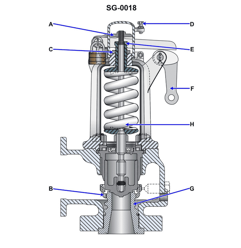
Question: The popping pressure of the safety valve, shown in the illustration, is controlled by the _ _. Illustration SG-0018
A. amount of spring compression
B. feather guide retaining ring
C. adjusting ring position
D. seat bushing adjustment
The correct answer is A) the amount of spring compression. The popping pressure of the safety valve is controlled by the amount of compression on the spring that holds the valve closed. Increasing the spring compression increases the pressure required to open the valve, while decreasing the compression lowers the opening pressure. This is the primary means of adjusting the valve's set pressure. The other options are not directly involved in controlling the popping pressure - the feather guide retaining ring, adjusting ring position, and seat bushing adjustment serve other functions in the valve design.
Question 448
Question: Which of the listed types of safety valves is shown in the illustration? Illustration SG-0018
A. Pressure-loaded type
B. Nozzle reaction type
C. Huddling chamber type
D. Jet flow type
The correct answer is C) Huddling chamber type. The illustration SG-0018 depicts a safety valve of the huddling chamber type. This type of safety valve is characterized by the presence of a huddling chamber, which helps to amplify the opening force acting on the valve disc, allowing the valve to open more quickly in response to an overpressure condition. The other options are incorrect because: A) Pressure-loaded type valves use the system pressure itself to open the valve, B) Nozzle reaction type valves use the force of the escaping fluid to open the valve, and D) Jet flow type valves utilize the kinetic energy of the fluid flow to open the valve. None of these descriptions match the design shown in the illustration.
Question 497
Question: The component lettered "J" shown in the illustration serves as a _______________. Illustration SG-0007
A. screen tube header
B. side water wall header
C. support beam
D. water drum
The correct answer is B) side water wall header. The side water wall header is a pipe that runs along the side of the boiler and distributes water to the water wall tubes. This component is responsible for supplying water to the water wall, which is a critical part of the boiler's heating system. The side water wall header ensures an even distribution of water throughout the water wall, allowing for efficient heat transfer and steam generation. The other answer choices are incorrect because they do not accurately describe the function of the component labeled "J" in the illustration. A screen tube header, a support beam, and a water drum serve different purposes within a boiler system and are not the correct identification for the component in question.
Question 508
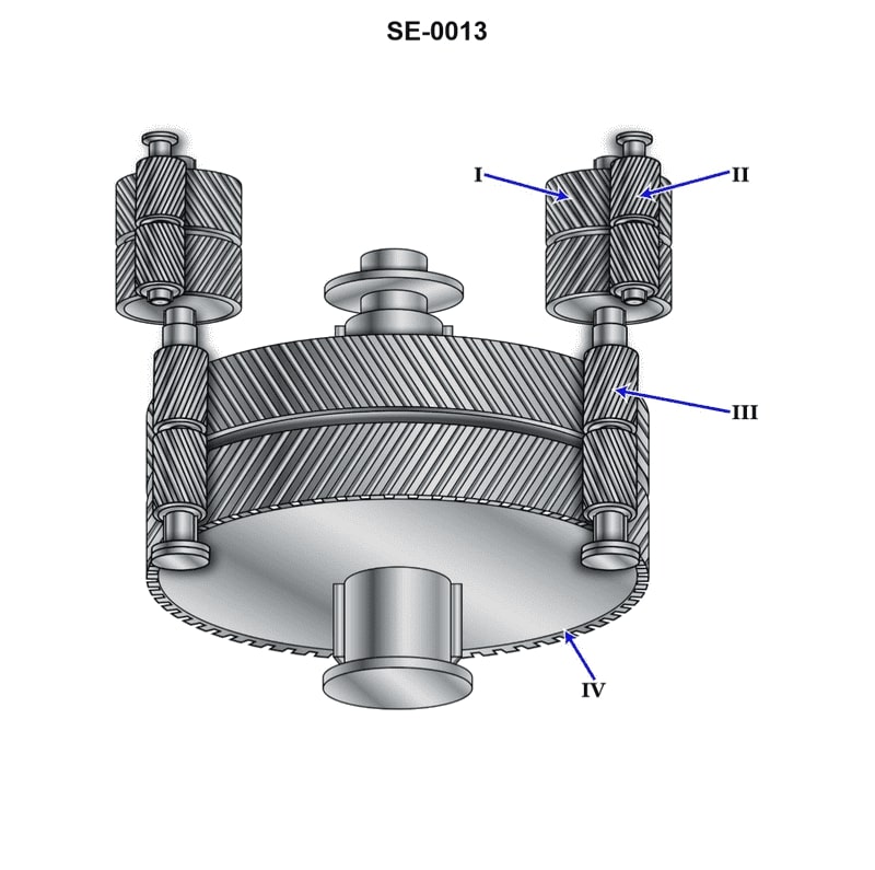
Question: The reduction gear shown in the illustration is a/an _______________. Illustration SE-0013
A. locked-train double reduction gear
B. nested four-step reduction gear
C. nested double reduction gear
D. articulated double reduction gear
The correct answer is D) articulated double reduction gear. This is correct because the illustration SE-0013 shows a reduction gear with two stages of reduction, where the gear shafts are arranged in an articulated or "broken" configuration rather than being in a straight line. This type of arrangement is known as an articulated double reduction gear. The other options are incorrect because they do not accurately describe the configuration shown in the illustration. A locked-train gear, nested four-step gear, and nested double reduction gear all have different arrangements of the reduction gearing that do not match the illustration.
Question 511
Question: The component shown in the illustration, labeled "I", is the _______________. SE-0013
A. first reduction pinion
B. first reduction gear
C. second reduction pinion
D. second reduction gear
The correct answer is B) first reduction gear. The first reduction gear is responsible for the initial reduction of the engine's rotational speed, which is necessary to match the propeller's optimal operating speed. This component is typically located within the transmission or reduction gear assembly, and its function is to provide the appropriate gearing ratio to efficiently transfer power from the engine to the propeller. The other answer choices are incorrect because: A) The first reduction pinion is a smaller gear that meshes with the first reduction gear. C) The second reduction pinion is a smaller gear that meshes with the second reduction gear. D) The second reduction gear is responsible for a further reduction in rotational speed, after the initial reduction by the first reduction gear.
Question 513
Question: The component shown in the illustration, labeled "III", is the SE-0013
A. first reduction gear
B. second reduction gear
C. low-speed pinion
D. high-speed pinion
The correct answer is C) low-speed pinion. The low-speed pinion, labeled as "III" in the illustration, is the component that transmits the rotational force from the engine to the reduction gears. This allows the high-speed engine to drive the slower-rotating propeller shaft. The low-speed pinion is a critical component in the propulsion system, as it enables the engine to efficiently transfer power to the propeller. The other options are incorrect because the first reduction gear (A) and second reduction gear (B) are separate components downstream of the low-speed pinion, while the high-speed pinion (D) is the component that meshes with the low-speed pinion to provide the initial reduction in rotational speed.
Question 515
Question: The component shown in the illustration, labeled "IV", is the SE-0013
A. bull gear
B. high-speed pinion
C. first reduction gear
D. low-speed pinion
The correct answer is A) bull gear. The component labeled "IV" in the illustration is the bull gear, which is a large, slow-rotating gear that is part of the reduction gear system in a marine propulsion system. The bull gear transfers power from the high-speed pinion to the low-speed propeller shaft, reducing the rotational speed while increasing the torque. The other answer choices are incorrect because the high-speed pinion (B) is a smaller, faster-rotating gear that meshes with the bull gear, the first reduction gear (C) is the initial stage of the reduction gear system, and the low-speed pinion (D) is a smaller gear that is part of the final stage of the reduction gear system.
Question 517
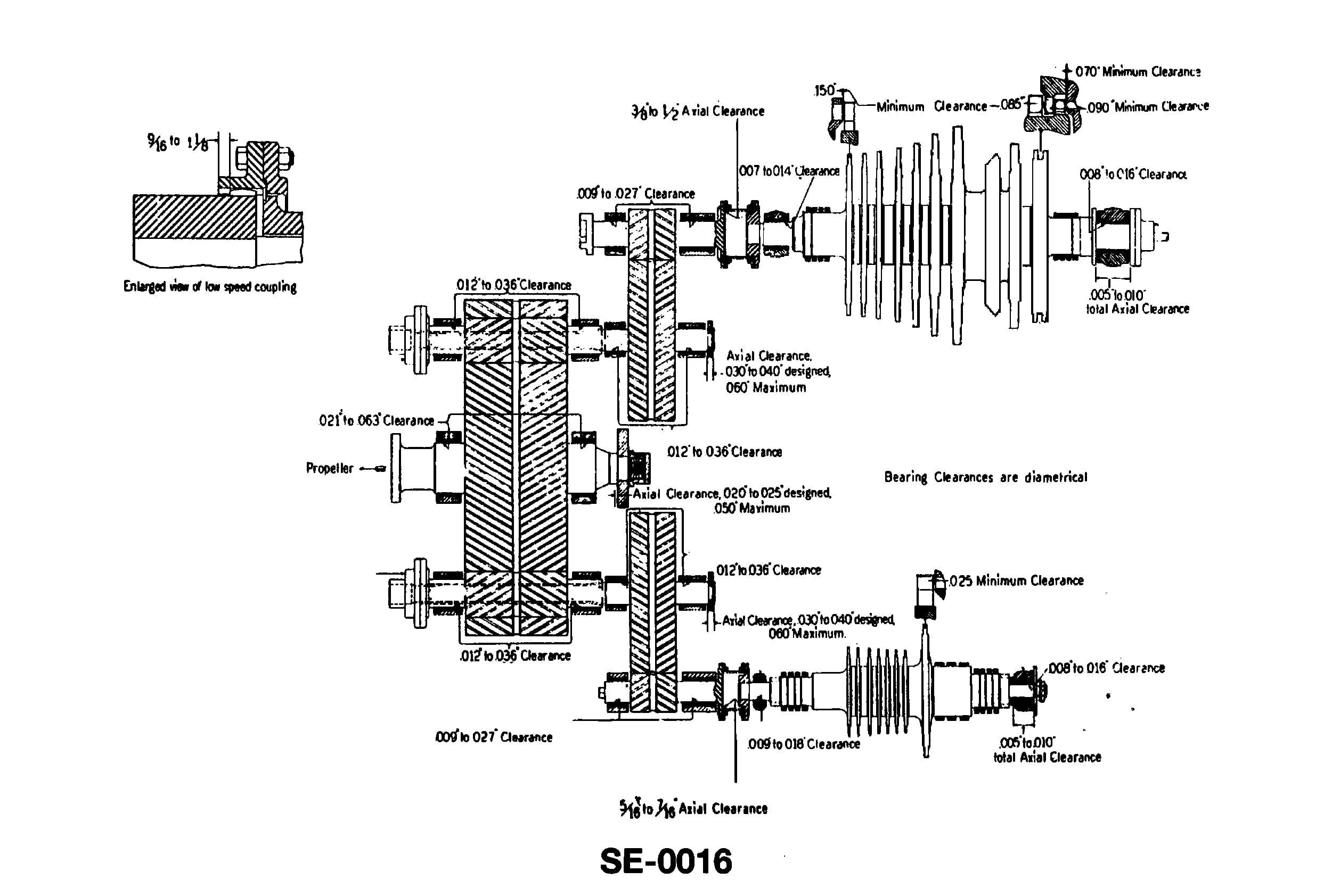
Question: A ship is equipped with the illustrated turbine gear set and a right hand turning propeller. When steam is admitted to the astern element, with sternway on, the high-speed gear on the high-pressure side is _______________. Illustration SE-0016
A. turning counter-clockwise as viewed from the aft end of the reduction gear
B. turning opposite to the rotation of the high-speed gear on the low-pressure side
C. turning the same rotation of the high-speed pinion on the low-pressure side
D. rotating the same direction as the low-speed pinion on the low-pressure side
The correct answer is D) rotating the same direction as the low-speed pinion on the low-pressure side. When steam is admitted to the astern element of a turbine gear set with a right-hand turning propeller, the high-speed gear on the high-pressure side will rotate in the same direction as the low-speed pinion on the low-pressure side. This is because the astern turbine element is designed to provide thrust in the opposite direction, causing the high-speed gear to rotate in the opposite direction to the forward rotation of the propeller. The other options are incorrect because A) and B) describe the rotation in the opposite direction, while C) describes the rotation in the same direction as the low-pressure side, which is not the case when the astern element is in use.

Question 526
Question: Which of the following statements is true concerning the lube oil system shown in the illustration? Illustration SE-0011
A. The gravity tank directly provides the normal supply of oil to the turbines and gears.
B. The gravity tank overflow line leads directly to the lube oil sludge tank.
C. The three-way temperature control valve bypasses cooling water around or through the lubricating oil cooler to maintain the desired oil temperature.
D. The drains from lube oil coolers can be directed back to the main sump, the sludge tank or the lube oil purifier.
The correct answer is D) The drains from lube oil coolers can be directed back to the main sump, the sludge tank or the lube oil purifier. This is correct because the lube oil system illustration shows multiple drain lines from the lube oil coolers, allowing the oil to be directed to different parts of the system, such as the main sump, sludge tank, or the lube oil purifier. This provides flexibility in managing the lube oil and ensuring proper circulation and purification. The other options are incorrect because: A) The gravity tank does not directly supply oil to the turbines and gears, but rather provides a backup supply; B) The gravity tank overflow line does not lead directly to the sludge tank; and C) The three-way temperature control valve is used to maintain the desired oil temperature, not to bypass the lube oil cooler.

Question 537
Question: In the diagrammatic arrangement of the thrust bearing, shown in the illustration, the direction of shaft rotation and the direction of thrust are indicated respectively by arrows . Illustration SE-0012
A. F and H
B. G and J
C. F and J
D. G and H
The correct answer is C) F and J. The direction of shaft rotation is indicated by the arrow F, and the direction of thrust is indicated by the arrow J in the diagrammatic arrangement of the thrust bearing shown in the illustration SE-0012. This is the correct answer because the thrust bearing is designed to support the axial or thrust loads imposed on the shaft, and the direction of the thrust load is typically opposite to the direction of shaft rotation. The illustration correctly depicts this relationship between the shaft rotation and thrust direction. The other options are incorrect because they do not accurately represent the relationship between the shaft rotation and thrust direction in the thrust bearing arrangement.
Question 539
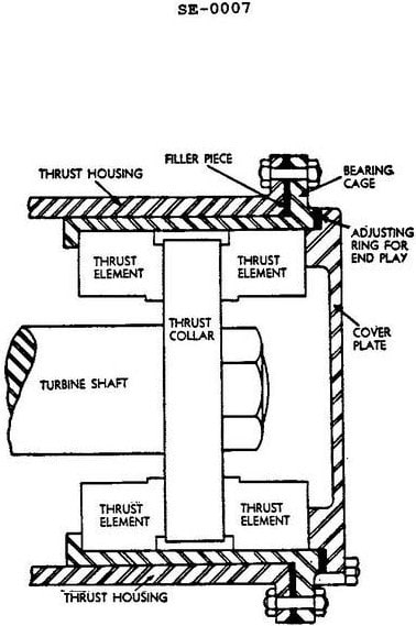
Question: In the thrust bearing assembly illustrated the total oil clearance can be correctly decreased by . Illustration SE-0007
A. increasing the thickness of the filler piece
B. decreasing the thickness of the adjusting ring
C. decreasing the thickness of the filler piece
D. increasing the thickness of the adjusting ring
The correct answer is B) decreasing the thickness of the adjusting ring. Explanation: Decreasing the thickness of the adjusting ring in the thrust bearing assembly will reduce the total oil clearance. This is because the adjusting ring is used to control the clearance between the thrust bearing and the thrust surfaces. Reducing the thickness of the adjusting ring will bring the thrust bearing closer to the thrust surfaces, thereby decreasing the overall oil clearance in the assembly. The other options are incorrect because increasing the thickness of the filler piece (A) or decreasing the thickness of the filler piece (C) would not directly affect the oil clearance in the thrust bearing assembly. Increasing the thickness of the adjusting ring (D) would have the opposite effect and increase the oil clearance, rather than decrease it.
Question 541
Question: The base ring shown in the illustration is identified by the letter _______________. Illustration SE-0012
A. A
B. E
C. C
D. D
The correct answer is D. The base ring shown in the illustration SE-0012 is identified by the letter D. This is based on the standard labeling conventions used in U.S. Coast Guard navigational aids and equipment illustrations. The letters A, C, E, and D are commonly used to label various components in these types of illustrations, and in this case, D corresponds to the base ring. The other answer choices are incorrect because A, C, and E do not match the labeling used in the specific illustration provided.
Question 545
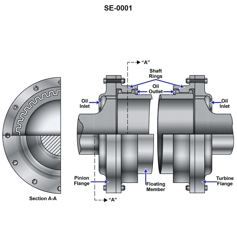
Question: Which of the coupling types listed is shown in the illustration? Illustration SE-0001
A. Claw
B. Pin
C. Gear
D. Solid
The correct answer is C) Gear. The illustration SE-0001 clearly shows a gear-type coupling, which is one of the common coupling types used in marine engineering. Gear couplings are designed to transmit rotational motion and power between two shafts, and they are often used in marine applications due to their reliability and ease of maintenance. The other answer choices, such as claw, pin, and solid couplings, have different designs and applications that do not match the coupling shown in the provided illustration.
Question 546
Question: Which of the following statements is true concerning the coupling shown in the illustration? Illustration SE-0001
A. It is commonly used between the first reduction pinion and the second reduction gear.
B. It is suitable for use on small auxiliary turbines only.
C. It allows for any misalignment between the main turbine and the second reduction gear.
D. It can be used to connect the main turbine to the high-speed pinion.
The correct answer is D) It can be used to connect the main turbine to the high-speed pinion. This type of coupling, known as a flexible or elastic coupling, is commonly used to connect the main turbine to the high-speed pinion in marine propulsion systems. The flexible design of the coupling allows for some misalignment between the turbine and pinion, which can occur due to thermal expansion, shaft deflection, or other factors. This helps to prevent excessive stress and wear on the components. The other answer choices are incorrect: A) This coupling is not typically used between the first reduction pinion and second reduction gear, as those components usually have a more rigid connection. B) The flexible coupling is not limited to use on small auxiliary turbines, but can be employed on larger main propulsion turbines as well. C) While the coupling does allow for some misalignment, this is not its primary purpose, which is to connect the turbine to the high-speed pinion.
Question 550
Question: The part shown in the illustration would be located between which of the following components of a modern geared turbine main propulsion unit? Illustration SE-0001
A. Between the bull gear and line shaft on the side of the gear opposite the thrust bearing.
B. Between the rotors and high-speed pinions of the high-pressure and low-pressure turbines.
C. Between the bull gear and line shaft on the thrust bearing side of the gear.
D. Between the first reduction gears and high-speed pinions of the high-pressure and low-pressure turbines.
The correct answer is B) Between the rotors and high-speed pinions of the high-pressure and low-pressure turbines. In a modern geared turbine main propulsion unit, the part shown in the illustration SE-0001 would be located between the rotors and high-speed pinions of the high-pressure and low-pressure turbines. This is the typical placement of the coupling or flexible connection that allows the transfer of power from the turbine rotors to the high-speed pinion gears. The other options are incorrect because they do not accurately describe the location of this component within the geared turbine system. The coupling is not located between the bull gear and line shaft, nor is it situated between the first reduction gears and high-speed pinions.
Question 561
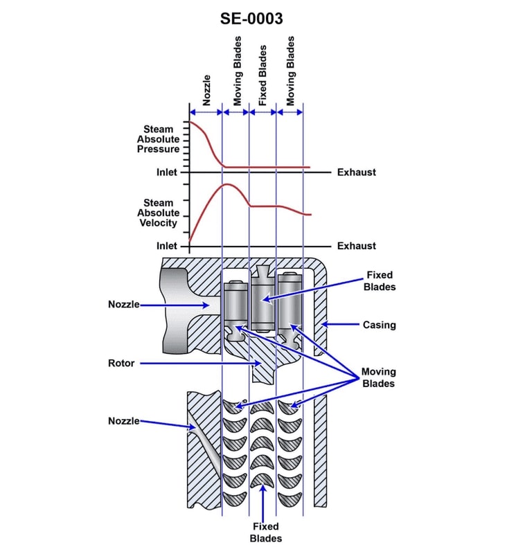
Question: The type of turbine shown in the illustration is classified as a Illustration SE-0003
A. pressure-compounded impulse
B. velocity-compounded impulse
C. pressure-compounded reaction
D. pressure-velocity compounded impulse
The correct answer is B) velocity-compounded impulse. This turbine type is classified as a velocity-compounded impulse turbine, where the steam expands through a series of nozzles, creating high-velocity steam jets that impinge on the turbine blades, transferring momentum and causing the turbine to spin. The velocity compounding refers to the steam flowing through multiple stages of stationary nozzles and moving blades to extract energy efficiently. The other options are incorrect because: A) pressure-compounded impulse turbines use pressure drops across the stationary blades rather than velocity; C) pressure-compounded reaction turbines rely more on pressure changes across the rotor blades; and D) pressure-velocity compounded impulse is not a standard turbine classification.
Question 563
Question: Design characteristics of a velocity-compounded impulse turbine include the utilization of _______________.
A. one or more nozzles with one row of rotating blades
B. a low velocity steam jet from a nozzle
C. two or more simple impulse stages
D. a single pressure stage with two or more velocity stages
The correct answer is D) a single pressure stage with two or more velocity stages. The design characteristics of a velocity-compounded impulse turbine include the utilization of a single pressure stage, which extracts some of the steam's pressure, followed by two or more velocity stages that extract the remaining energy from the steam's velocity. This configuration allows the turbine to more efficiently convert the steam's energy into mechanical work compared to a simple impulse turbine with only one row of rotating blades. The other options are incorrect because they do not accurately describe the key design features of a velocity-compounded impulse turbine. Option A describes a simple impulse turbine, option B describes a low-velocity steam jet, and option C describes a multi-stage impulse turbine without the pressure stage.

Question 566
Question: Which of the listed parts illustrated in the turbo-generator governing system, provides the follow-up to prevent the nozzle valves from cycling between the fully open and fully closed positions, with each variation in turbine speed? Illustration SE-0009
A. E
B. H
C. O
D. D
The correct answer is A) E. The element labeled "E" in the illustration SE-0009 of the turbo-generator governing system provides the follow-up mechanism to prevent the nozzle valves from cycling between the fully open and fully closed positions. This follow-up mechanism is a critical component that helps maintain the stability of the turbine speed by dampening rapid changes and preventing the valves from oscillating. The other options are incorrect because they do not directly correspond to the follow-up mechanism in the governing system. Option B) H likely represents the speed setting device, Option C) O could be the overspeed trip, and Option D) D may be the nozzle control valve, but none of these components specifically provide the follow-up function described in the question.
Question 570
Question: Which of the listed actions will occur when there is an increase in load on a ship service generator equipped with a centrifugal type hydraulic governor? Illustration SE-0009
A. Steam flow to the turbine decreases.
B. More oil will enter the operating cylinder (O).
C. The governor weights move outward.
D. The operating piston is forced to move lower.
The correct answer is B) More oil will enter the operating cylinder (O). When there is an increase in load on a ship service generator equipped with a centrifugal type hydraulic governor, the governor weights will move outward, causing the operating piston to move upward. This upward movement of the operating piston will allow more oil to enter the operating cylinder (O), which in turn will increase the force on the valve mechanism, allowing more steam to flow to the turbine to meet the increased load demand. The other options are incorrect because: A) Steam flow to the turbine would increase, not decrease, to meet the increased load. C) The governor weights moving outward is the cause of the increased oil flow, not the result. D) The operating piston is forced to move upward, not lower, to allow more oil flow.

Question 571
Question: Which of the statements listed applies to the quill shaft shown in the illustration? Illustration SE-0005
A. It absorbs the axial thrust generated by the meshing gears.
B. It permits axial movement between the high-speed gear and low-speed pinion.
C. It compensates for high-speed pinion radial misalignment.
D. It provides torsional rigidity to help maintain alignment between gear train and the turbine rotor.
The correct answer is B) It permits axial movement between the high-speed gear and low-speed pinion. The quill shaft allows for axial movement between the high-speed gear and low-speed pinion, which is necessary to accommodate thermal expansion and other dimensional changes in the drive train. This ensures that the gears can maintain proper alignment and engagement despite minor movements, preventing binding or excessive wear. The other answer choices are incorrect because: A) The quill shaft does not absorb axial thrust, which is typically handled by other components like thrust bearings. C) The quill shaft does not compensate for radial misalignment, which is usually addressed through proper bearing and shaft design. D) The quill shaft provides torsional flexibility, not rigidity, to allow for relative movement between components.
Question 574
Question: In the illustration of a typical ship service turbo-generator control system, the handle labeled "B" is used to _______________. Illustration SE-0009
A. pump up the lube oil manifold
B. reset the over speed trip
C. bypass the governor control
D. roll over the high-speed pinion
The correct answer is B) reset the over speed trip. The handle labeled "B" in the illustration of a typical ship service turbo-generator control system is used to reset the over speed trip. The over speed trip is a safety mechanism that automatically shuts down the turbo-generator if it exceeds a safe operating speed. Resetting this trip allows the operator to restart the turbo-generator after an over speed event. The other answer choices are incorrect because they do not accurately describe the function of the "B" handle. Pumping up the lube oil manifold, bypassing the governor control, and rolling over the high-speed pinion are not the primary purposes of this particular control on the turbo-generator system.
Question 611
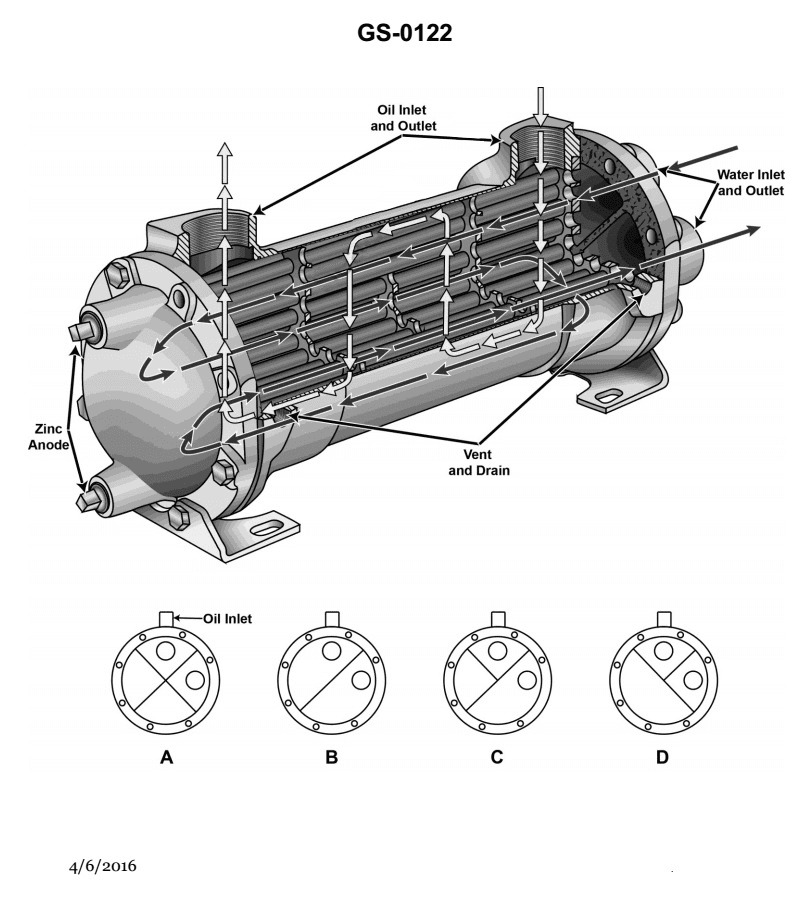
Question: What type of lube oil cooler is shown in the illustration? Illustration GS-0122
A. Plate type
B. Shell-and-tube
C. Bundle and stack
D. Self-venting
The correct answer is B) Shell-and-tube. The shell-and-tube type lube oil cooler is commonly used in marine applications, including those found on U.S. Coast Guard vessels. This design features a shell that encloses a bundle of tubes, with the lube oil flowing through the tubes and the cooling medium (typically seawater or freshwater) flowing over the outside of the tubes within the shell. This configuration allows for efficient heat transfer between the lube oil and the cooling medium, making it a suitable choice for marine engine applications. The other options are not correct because a plate-type cooler (A) has a different construction, a bundle-and-stack cooler (C) is a less common design, and a self-venting cooler (D) is a specialized type not typically found in the illustration provided.
Question 689
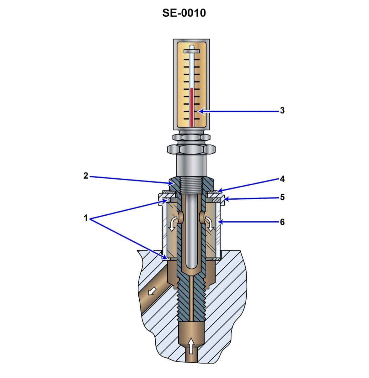
Question: According to the illustration, what is the normal function of the component shown? Illustration SE-0010
A. indicate the pressure and temperature of lube oil leaving a turbine bearing
B. indicate the pressure and flow of lube oil entering a turbine bearing
C. act as a final filter for oil entering a bearing
D. indicate the temperature and flow of lube oil leaving a turbine bearing
The correct answer is D) indicate the temperature and flow of lube oil leaving a turbine bearing. This is correct because the illustration SE-0010 depicts a component that is typically used to monitor the temperature and flow of the lubricating oil as it exits a turbine bearing. Monitoring these parameters is important for ensuring proper lubrication and preventing damage to the bearing. The other answer choices are incorrect because they do not accurately describe the normal function of the component shown in the illustration. Option A refers to monitoring the oil leaving the bearing, while option B refers to monitoring the oil entering the bearing. Option C describes a filtration function, which is not the primary purpose of the component depicted.
Question 702
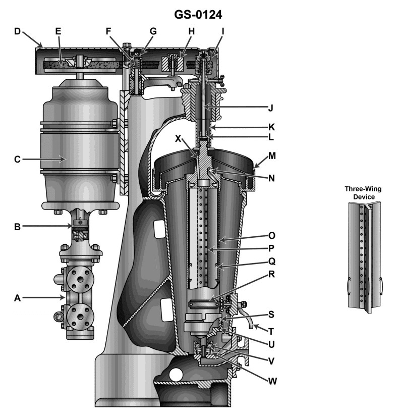
Question: The three wing device in the unit illustrated is maintained in its position by item . Illustration GS-0124
A. O
B. P
C. Q
D. R
The correct answer is C) Q. The three-wing device in the unit illustrated is maintained in its position by item Q, which is the adjusting screw. This screw is used to adjust the position and tension of the three-wing device, ensuring it remains securely in place. The other answer choices are incorrect because: A) O is the main body of the unit, which does not directly maintain the position of the three-wing device. B) P is the wing pivot, which allows the three-wing device to move, but does not maintain its position. D) R is the wing, which is part of the three-wing device itself, not the mechanism that keeps it in place.
Question 706
Question: Water removed through centrifugal force in the illustrated unit is displaced from the bowl through . Illustration GS-0124
A. K
B. N
C. V
D. X
The correct answer is B) N. The water removed through centrifugal force in the illustrated unit (GS-0124) is displaced from the bowl through the discharge port or nozzle, which is labeled as "N" in the illustration. The centrifugal force generated by the spinning bowl separates the water from the fuel, and the water is then expelled through the discharge port or nozzle, which is the correct answer choice. The other options, A) K, C) V, and D) X, do not correspond to the specific components shown in the illustration that are responsible for discharging the water separated from the fuel.
Question 720
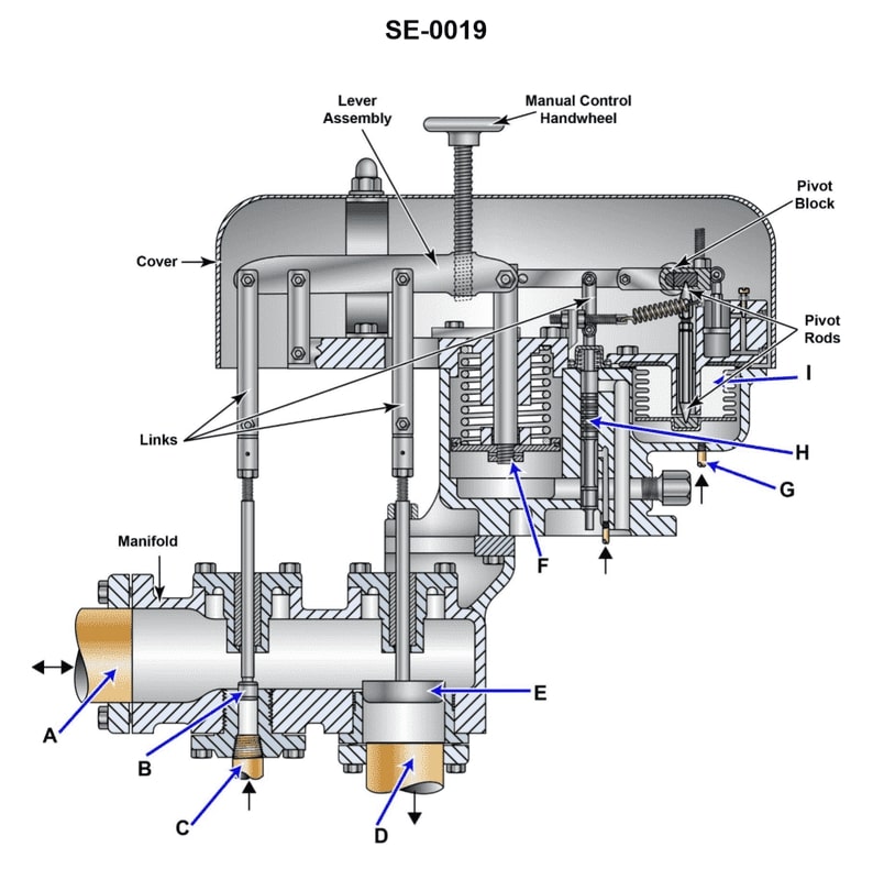
Question: As shown in the illustration bellows "I" in the gland seal regulator is actuated by _______________. Illustration SE-0019
A. control air pressure
B. gland seal steam pressure
C. lube oil pressure
D. steam throttle pressure
The correct answer is B) gland seal steam pressure. The gland seal regulator in the illustration is used to regulate the steam pressure in the gland seal, which is a critical component in maintaining the integrity of the steam system. The "I" in the illustration represents the point where the gland seal steam pressure actuates the regulator, controlling the flow of steam to the gland seal and maintaining the desired pressure. The other options are incorrect because they do not directly regulate the gland seal steam pressure. Control air pressure (A), lube oil pressure (C), and steam throttle pressure (D) may be related to the overall steam system, but they do not specifically control the gland seal steam pressure as indicated in the illustration.
Question 721
Question: For the gland seal regulator shown in the illustration, an increase in gland seal pressure will result in _ . Illustration SE-0019
A. piston "F" moving upward to open the makeup steam valve "B" and close the exhaust valve "E"
B. piston "F" moving downward to shut the makeup steam valve "B" and open the exhaust valve "E"
C. piston "F" moving downward to open the makeup steam valve "B" and close the exhaust valve "E"
D. piston "F" moving upward to shut the makeup steam valve "B" and open the exhaust valve "E"
The correct answer is D) piston "F" moving upward to shut the makeup steam valve "B" and open the exhaust valve "E". Explanation: An increase in gland seal pressure will cause piston "F" to move upward, which will shut the makeup steam valve "B" and open the exhaust valve "E". This allows the excess pressure to be released through the exhaust valve, rather than admitting more makeup steam through valve "B". The other answer choices describe the opposite movement of the piston, which would not be the correct response to an increase in gland seal pressure.
Question 724
Question: As shown in the illustration, live steam is supplied to the gland seal regulator via _______________. Illustration SE-0019
A. line "A"
B. line "G"
C. line "C"
D. line "D"
The correct answer is C) line "C". The illustration SE-0019 shows a diagram of a gland seal regulator, and the question asks which line supplies live steam to the regulator. Based on the diagram, line "C" is the line that supplies live steam to the gland seal regulator. The other answer choices are incorrect because: A) Line "A" appears to be the steam supply to the engine, not the gland seal regulator. B) Line "G" is labeled as the "Exhaust" line, so it does not supply live steam. D) Line "D" is labeled as the "Drain" line, so it also does not supply live steam to the regulator.
Question 726
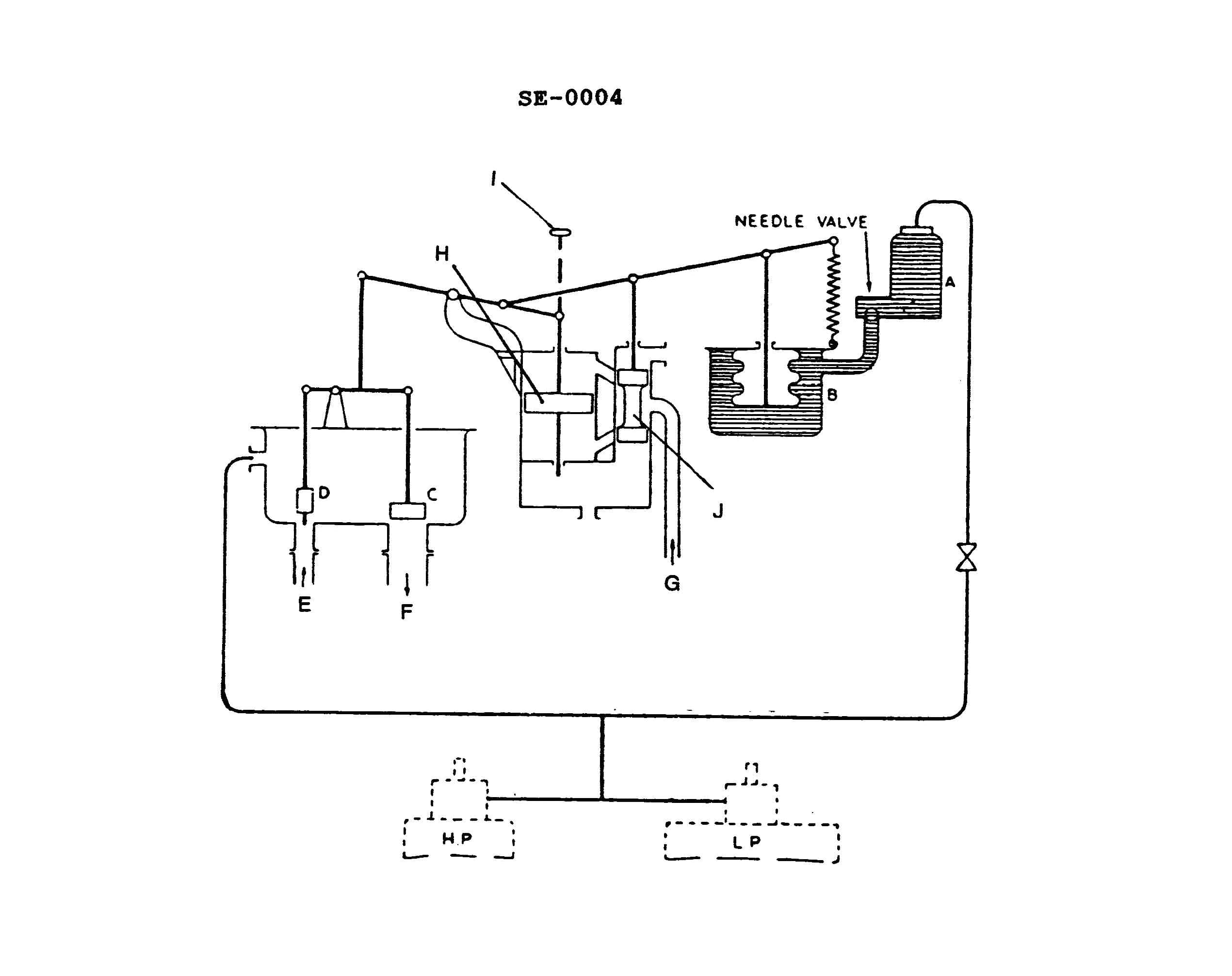
Question: During maneuvering, a vessel has just reached full ahead from a dead slow condition. Which of the following actions reflects the first operation of the gland seal regulator shown in the illustration? Illustration SE-0004
A. Pilot valve bushing would move downward.
B. Valve "D" would move upward.
C. Bellows and connecting link would move upward.
D. Needle valve would automatically become seated.
The correct answer is C) Bellows and connecting link would move upward. When a vessel reaches full ahead from a dead slow condition, the engine speed and power output will increase rapidly. This increased power output will result in higher pressure in the engine's gland seal regulator, which is designed to maintain proper sealing pressure around the engine's shaft. In response to this increased pressure, the bellows and connecting link in the gland seal regulator will move upward, as this is the first operation that occurs to regulate the increased pressure. The other answer choices are incorrect because they do not accurately describe the initial response of the gland seal regulator to the change in engine power. The pilot valve bushing, valve "D", and needle valve do not directly respond to the increased pressure in the same way as the bellows and connecting link.
Question 727
Question: As shown in the illustration, piston "F" in the gland seal regulator is moved upward by _. Illustration SE-0019
A. lube oil pressure
B. control air
C. nitrogen
D. steam pressure
The correct answer is A) lube oil pressure. In a gland seal regulator, piston "F" is moved upward by the lube oil pressure. The lube oil pressure acts on the underside of the piston, pushing it upward and regulating the flow of fluid or gas through the regulator. The other options are incorrect because: B) Control air is used to actuate the regulator, but does not directly move the piston. C) Nitrogen is an inert gas that may be used in the regulator system, but does not directly move the piston. D) Steam pressure is not involved in the operation of a gland seal regulator.
Question 729
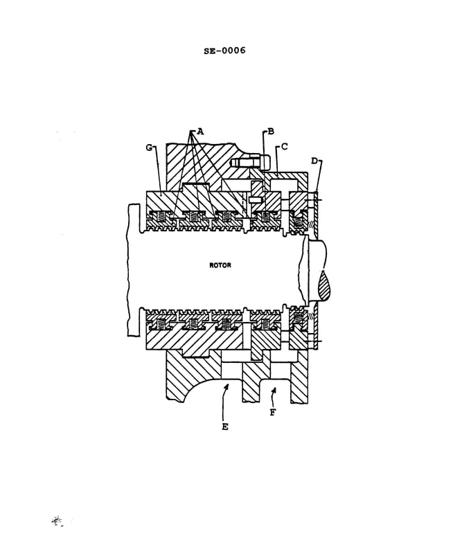
Question: If the gland assembly shown in the illustration is located at the forward end of the high-pressure turbine and the vessel is operating at full speed ahead_______________. Illustration SE-0006
A. this gland would be self-sealing and provide sealing steam to the other glands
B. A slight vacuum would exist at "E"
C. sealing steam would only enter at "F"
D. sealing steam would enter at "E" and "F" from the LP turbine
The correct answer is A) this gland would be self-sealing and provide sealing steam to the other glands. The gland assembly located at the forward end of the high-pressure turbine is responsible for sealing the turbine shaft and preventing the escape of high-pressure steam. When the vessel is operating at full speed ahead, the high-pressure turbine is under a significant load, and the gland assembly needs to be self-sealing to maintain the proper steam pressure within the turbine. This self-sealing feature allows the gland to provide the necessary sealing steam to the other glands in the system, ensuring the overall integrity of the turbine and the vessel's propulsion system. The other options are incorrect because they do not accurately describe the function of the gland assembly in the given scenario. Option B is incorrect as a slight vacuum would not exist at "E" when the vessel is operating at full speed ahead. Option C is incorrect as sealing steam would enter both "E" and "F" from the high-pressure turbine. Option D is incorrect as the sealing steam would not come from the low-pressure turbine in this case.
Question 732
Question: In the event of failure of bellows "I" as shown in the illustration, SE-0019 . Illustration
A. piston "F" moves downward to open the exhaust valve and close the steam makeup valve
B. piston "F" moves downward to close the exhaust valve and open the steam makeup valve
C. piston "F" moves upward to close the exhaust valve and open the makeup steam valve
D. piston "F" moves upward to open the exhaust valve and close the makeup steam valve
The correct answer is B) piston "F" moves downward to close the exhaust valve and open the steam makeup valve. In the event of a failure of bellows "I", the piston "F" will move downward to close the exhaust valve and open the steam makeup valve. This action is necessary to maintain the proper steam pressure in the system by allowing makeup steam to enter and compensate for the loss of pressure due to the bellows failure. The other options are incorrect because they do not accurately describe the proper response to a bellows failure. Option A would result in the opposite action, opening the exhaust valve and closing the makeup valve, which would further reduce the system pressure. Options C and D describe the piston moving upward, which is the incorrect direction for the given failure scenario.
Question 733
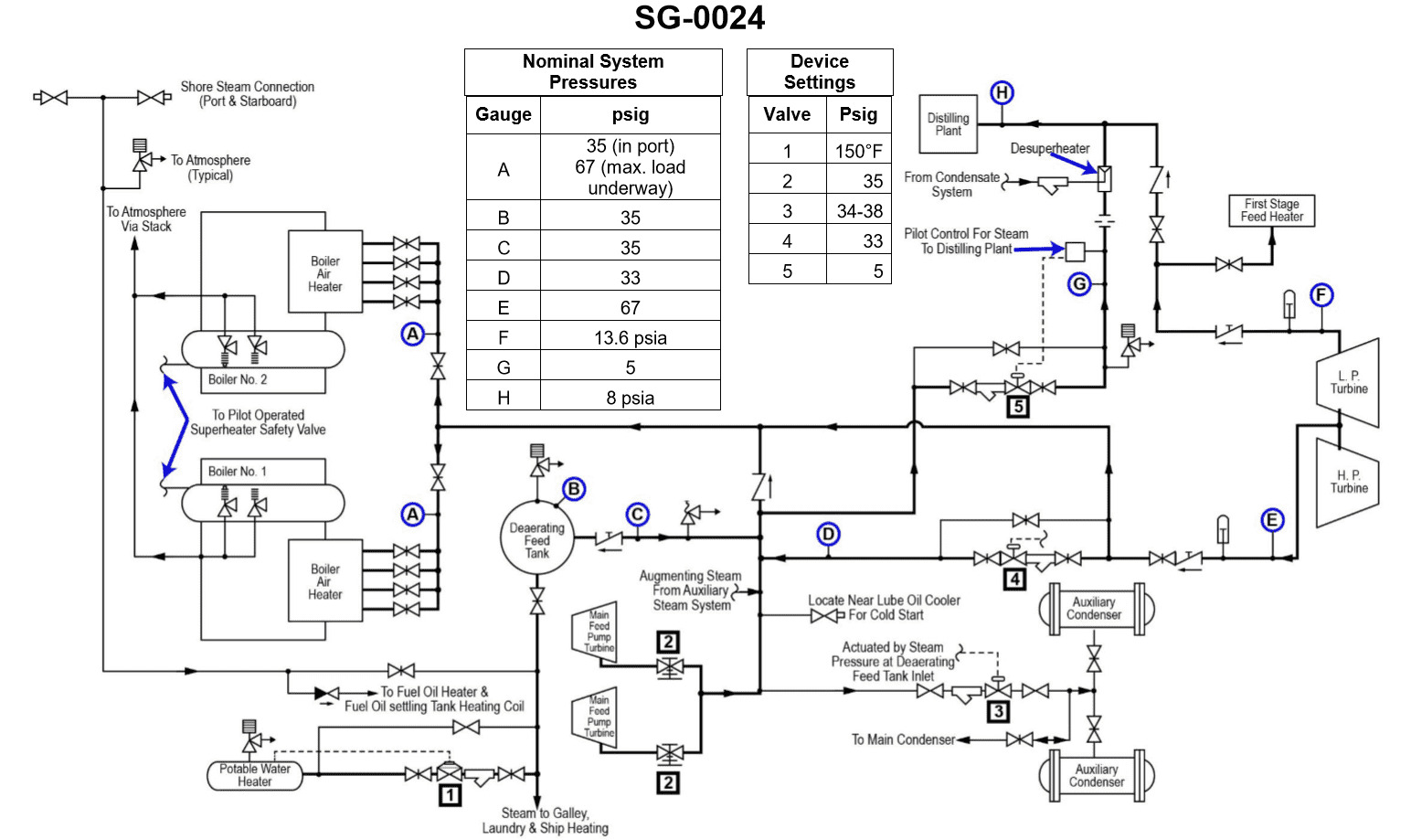
Question: The intermediate pressure bleed steam system, shown in the illustration, is used to supply steam at approximately _______________. Illustration SG-0024
A. 13.6 psia
B. 13.6 psig
C. 35.0 psig
D. 67.0 psig
The correct answer is D) 67.0 psig. The intermediate pressure bleed steam system is used to supply steam at approximately 67.0 psig. This is based on the typical operating pressure range for this type of steam system on commercial vessels. The intermediate pressure bleed steam is taken from the main steam system at a point where the pressure is around 67 psig, which is lower than the main steam pressure but higher than the low-pressure steam used for other purposes. The other answer choices are incorrect because 13.6 psia is an absolute pressure measurement, not a gauge pressure, and 13.6 psig and 35.0 psig are not the typical pressures for an intermediate pressure bleed steam system on a commercial vessel.
Question 744
Question: Which of the following statements is true concerning the piping system shown in the illustration? Illustration SG-0005
A. The boiler soot blowers operate with desuperheated steam.
B. Air ejectors operate on 143 psi steam.
C. The steam whistle operates on 140 psi steam.
D. All of the above.
The correct answer is D) All of the above. The illustration SG-0005 shows a piping system with various components operating on different steam pressures. The statement that the boiler soot blowers operate with desuperheated steam, the air ejectors operate on 143 psi steam, and the steam whistle operates on 140 psi steam are all correct based on the information provided in the illustration. The other answer options are incorrect because they do not accurately describe the details shown in the piping system diagram. This type of question is common on US Coast Guard Captain's License Examinations, where candidates are expected to demonstrate their understanding of marine engineering systems and components.
Question 745
Question: Which of the piping systems listed is shown in the illustration? Illustration SG-0005
A. Auxiliary exhaust
B. Butterworth
C. Main feed
D. Auxiliary steam
The correct answer is D) Auxiliary steam. The illustration SG-0005 depicts a piping system that is most likely an auxiliary steam system, which is used to distribute steam for various auxiliary functions on board a vessel, such as heating, ventilation, and steam-driven equipment. This type of piping system is commonly found on larger commercial vessels, including those that may require a U.S. Coast Guard Captain's License. The other options are not as likely to be depicted in this particular illustration. Auxiliary exhaust, Butterworth, and main feed systems serve different functions and have distinct piping configurations that would not match the illustration.