Pass Your Coast Guard Licensing Exams!
Study offline, track your progress, and simulate real exams with the Coast Guard Exams app
QMED05 - Machinist-Pump Technician
13 images
Question 5
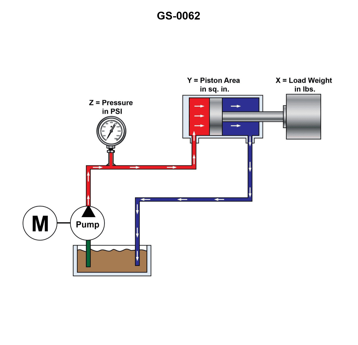
Question: In the system illustrated, which of the following readings should be indicated on the pressure gauge, if the load (x) is 8000 lbs. (3632 kg) and the piston area (y) is 10 sq. in (64.5 sq. cm)? Illustration GS-0062
A. 80 psi (5.63 kg/cm2)
B. 800 psi (56.31 kg/cm2)
C. 8,000 psi (563.1 kg/cm2)
D. 80,000 psi (5631 kg/cm2)
The Correct Answer is B **Explanation for Option B (Correct Answer):** The pressure exerted on a fluid in a hydraulic system is calculated using the formula: $$\text{Pressure (P)} = \frac{\text{Force (F)}}{\text{Area (A)}}$$ In this problem: 1. **Force (F)** (which is the load, x) = 8000 lbs. 2. **Area (A)** (the piston area, y) = 10 sq. in. Substituting the values into the formula: $$P = \frac{8000 \text{ lbs}}{10 \text{ sq. in.}}$$ $$P = 800 \text{ pounds per square inch (psi)}$$ Therefore, the pressure gauge should indicate 800 psi. **Explanation of Incorrect Options:** * **A) 80 psi (5.63 kg/cm2):** This value is incorrect. It would result from dividing the force (8000 lbs) by an area of 100 sq. in., or by misplacing the decimal point in the correct calculation (8000 / 10 = 800). * **C) 8,000 psi (563.1 kg/cm2):** This value is incorrect. It results from assuming the area was 1 sq. in. ($8000 \text{ lbs} / 1 \text{ sq. in.} = 8000 \text{ psi}$), or by mistakenly multiplying the load by the area instead of dividing. * **D) 80,000 psi (5631 kg/cm2):** This value is incorrect. It would result if the area was 0.1 sq. in. or if the load was mistakenly taken as 800,000 lbs. This pressure is excessively high for the given parameters.
Question 6
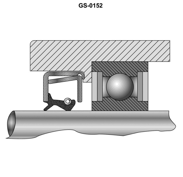
Question: Spring reinforced oil seals for retention of lubricant, are installed with the lip of the seal facing __________. Illustration GS-0152
A. toward the bearing preload washer
B. away from the bearing housing recess
C. away from the oil pressure being sealed
D. toward the oil pressure being sealed
The Correct Answer is D **Explanation of Correct Option (D):** Spring-reinforced oil seals (lip seals) are designed to retain fluid (lubricant) within a system while excluding contaminants. The primary sealing element is the flexible lip, which is held against the rotating shaft by tension and often reinforced by a garter spring. For effective sealing, the sharp edge of the lip must face the pressure (the volume of fluid being retained). When the seal is installed with the lip facing **toward the oil pressure being sealed**, the internal pressure of the lubricant acts on the back side of the flexible lip, slightly deflecting it. This pressure action aids the garter spring in pressing the lip more firmly against the shaft, enhancing the sealing force and preventing the lubricant from escaping. **Explanation of Incorrect Options:** * **A) toward the bearing preload washer:** While the seal is often installed adjacent to a bearing, referencing the "bearing preload washer" (a component used for setting bearing tension) does not universally define the direction of the fluid pressure. The physical orientation of the lip must be dictated by the fluid pressure location, not just an adjacent structural component. * **B) away from the bearing housing recess:** This description is too vague regarding the fluid dynamics. The critical factor is the fluid being retained. If the seal is installed "away" from the fluid being retained, the pressure would push the lip open, allowing leakage. * **C) away from the oil pressure being sealed:** If the lip is installed facing *away* from the oil pressure, the pressure being sealed would act on the outer casing or the back of the lip assembly. This pressure would tend to lift the lip away from the shaft, causing immediate and significant leakage, defeating the purpose of the seal.
Question 7
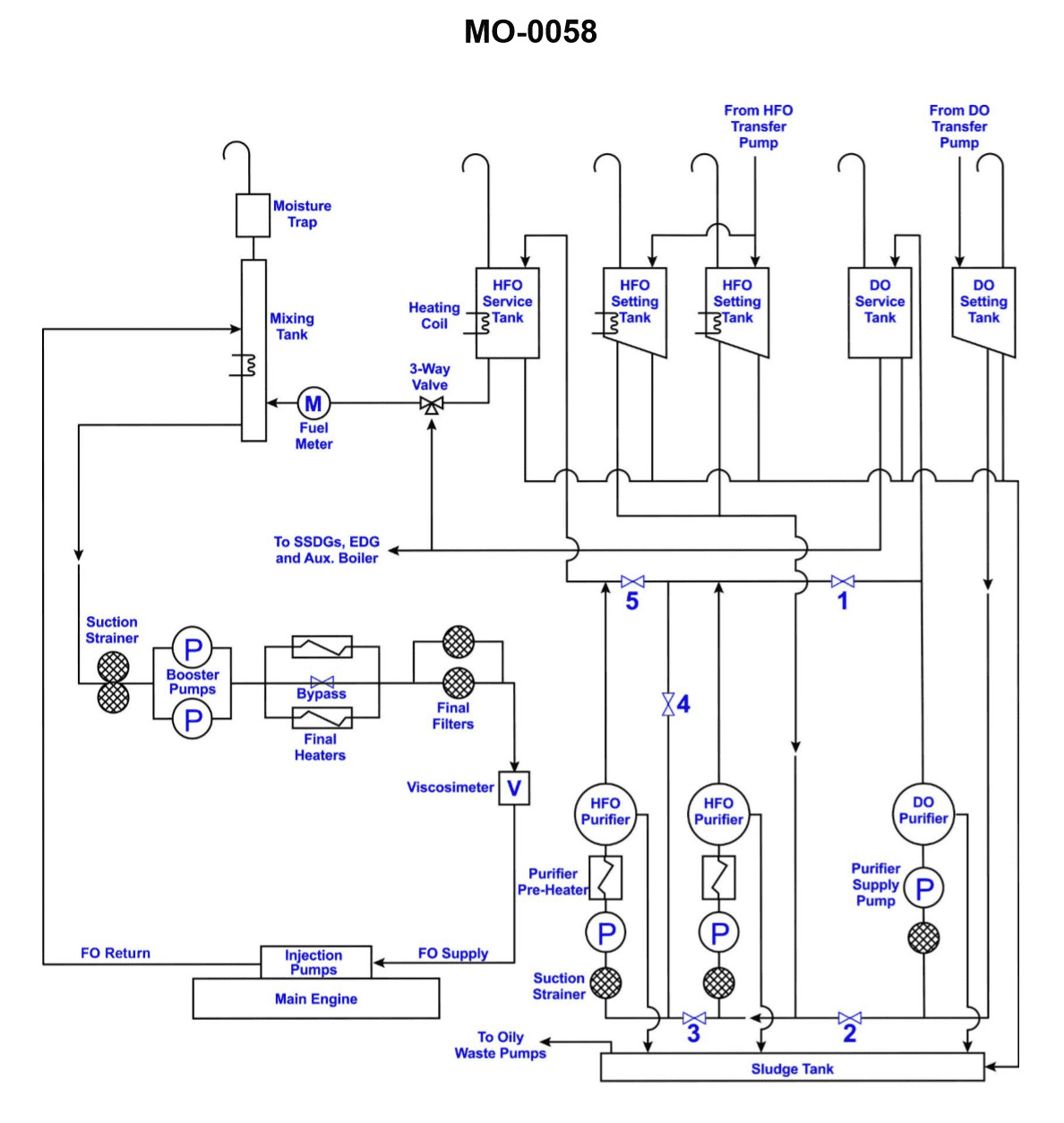
Question: Which of the tanks, shown in the illustration, supplies fuel to the emergency generator? Illustration MO-0058
A. Diesel Oil Service Tank
B. Diesel Oil Settling Tank
C. Diesel Oil Boiler Tank
D. Diesel Oil Booster Tank
The Correct Answer is A. ### Why Option A ("Diesel Oil Service Tank") is correct: The **Diesel Oil Service Tank** (or Day Tank) is specifically designed to hold a readily available supply of fuel sufficient for the immediate operation of critical machinery, such as the emergency generator, for a predetermined period (often 24 hours). In any marine or industrial setup, the emergency generator must start instantly and operate reliably, and the service tank provides this uncontaminated, gravity-fed (or low-pressure pumped) source of fuel directly to the generator's engine. ### Why the other options are incorrect: **B) Diesel Oil Settling Tank:** This tank is used for storing the fuel received from the bunker tanks for a period of time to allow water and heavy impurities (sludge) to naturally separate and settle at the bottom before the fuel is processed. It is a preliminary storage point, not the final supplier of fuel to the engine. **C) Diesel Oil Boiler Tank:** This term is non-standard in typical diesel generator fuel systems. Boilers usually use Heavy Fuel Oil (HFO) or Marine Gas Oil (MGO), and while their storage may be heated, a dedicated "Boiler Tank" is not part of the emergency generator supply chain. **D) Diesel Oil Booster Tank:** A Booster Tank (or Head Tank) is often used to ensure adequate pressure or flow rate to a system, but it is typically fed *from* the Service Tank or acts as a header tank within a pressurized distribution loop. The primary tank supplying the fuel for immediate use by the emergency generator is the Service Tank.
Question 11
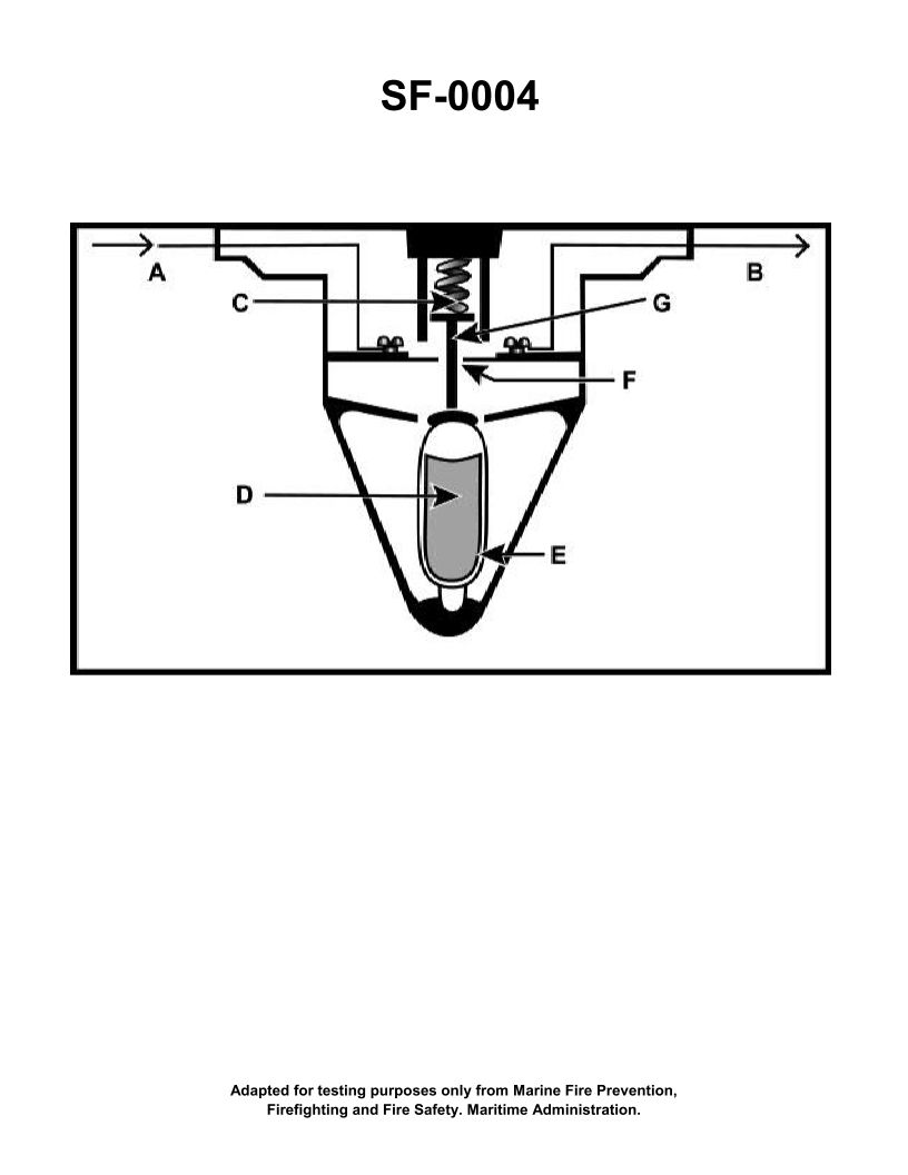
Question: The component shown in the illustration would be installed in which of the following types of fire detection systems? Illustration SF-0004
A. Fixed temperature
B. Line type pneumatic
C. Combined fixed temperature and rate-of-rise
D. Rate-of-rise
The Correct Answer is A **Explanation for Option A (Fixed temperature):** The component likely shown in Illustration SF-0004 (which is implied to be a common thermal detection device) is a fixed-temperature heat detector, such as a fusible alloy (solder) or bimetallic strip type. These detectors are designed to activate when the ambient temperature reaches a specific, predetermined level (e.g., $135^\circ\text{F}$ or $194^\circ\text{F}$). If the illustration depicts a common single-point thermal sensing element that operates purely based on reaching a defined heat threshold, it is characteristic of a **fixed temperature** fire detection system. **Explanation for Incorrect Options:** **B) Line type pneumatic:** This is incorrect. Line type pneumatic systems use a continuous tube run through the protected area, often connected to an air pressure sensing device (diaphragm or capsule). The detector shown in the illustration is a point-type sensor, not a continuous pneumatic tube assembly. **C) Combined fixed temperature and rate-of-rise:** This is incorrect. While this type of detector exists, it uses two distinct sensing mechanisms (one for the fixed temperature threshold and one for rapid temperature change). Unless the illustration explicitly shows both components (e.g., a fusible link alongside an air chamber with a vent), it represents only the fixed-temperature function, making Option A the most precise categorization for a standard fixed-temperature component. **D) Rate-of-rise:** This is incorrect. Rate-of-rise detectors (typically utilizing an air chamber that expands due to rapidly rising heat) are designed to trigger alarms based on how quickly the temperature increases (e.g., $15^\circ\text{F}$ per minute), not just reaching a specific absolute temperature threshold. The component described by the function inherent in the fixed-temperature system (Option A) operates solely on reaching that temperature threshold.

Question 19
Question: Which of the projections represents the left side view of the object "X" in the illustration? Illustration GS-0022
A. A
B. B
C. C
D. D
The Correct Answer is A **Explanation for Option A (A) being correct:** Projection A correctly represents the left side view of the object "X". When viewing the object from the left side, the following features are visible: 1. **Overall Shape:** The projection shows the overall height and depth (which becomes the width in this view) of the main rectangular block. 2. **"L" Cutout Feature:** The deep "L" shaped cutout visible on the front and top surfaces of the object translates into a large rectangular notch or missing section viewed from the left. This cutout goes from the top edge down towards the bottom and across from the front edge towards the back, meaning the left side view should show the remaining back corner as a solid rectangle, and the space created by the cutout as an empty area. Projection A accurately displays this resulting shape: a tall, narrow rectangle on the right side (representing the rear section of the object) and a lower, wider section on the left side (representing the front section's height). The overall profile matches the view obtained when looking directly at the left face. **Explanation for why other options are incorrect:** * **Option B (B):** Projection B is incorrect. It appears to represent the **right side view** of the object. When viewed from the right, the object would look like a simple solid rectangle, as the "L" cutout is located on the opposite (left) side and does not break the continuity of the right face. * **Option C (C):** Projection C is incorrect. This projection appears to represent the **front view** of the object. The front view clearly shows the main rectangular shape with the upper-left corner removed by the "L" cutout, resulting in a distinct "L" shape profile, but viewed from the front, not the side. * **Option D (D):** Projection D is incorrect. This projection appears to represent the **top view** of the object. The top view shows the overall width and depth, with the "L" cutout visible as a notch in the front-left corner of the rectangular outline.
Question 19
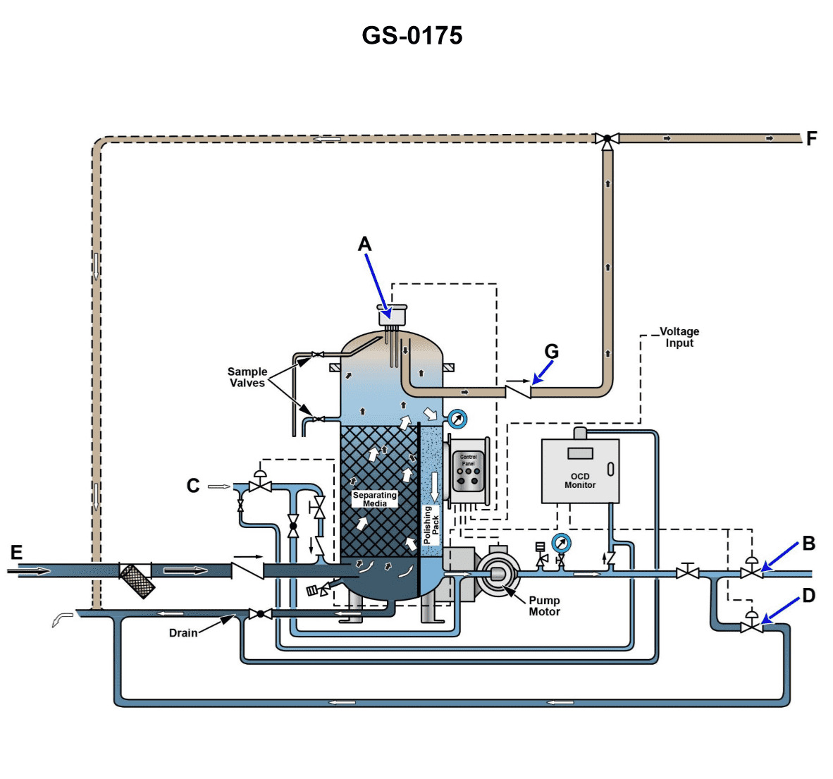
Question: The line labeled "C", as shown in the illustration, would be identified as the _____. Illustration GS-0175
A. oily bilge water inlet
B. clean water flushing line
C. tank drain line
D. oil discharge line
The Correct Answer is B ### Explanation for Option B (clean water flushing line) Illustration GS-0175 typically depicts components related to an Oily Water Separator (OWS) or sludge handling system found in maritime environments. Line "C" is identified as the **clean water flushing line** because, in such systems, it is necessary to periodically clean internal components (like the separation elements or the chambers) to prevent fouling by oil and solids, ensuring the system operates efficiently. This line introduces clean water (often fresh water or seawater) into the system for maintenance and cleaning purposes, especially when preparing the system for layup or inspection. ### Why the Other Options Are Incorrect **A) oily bilge water inlet:** This line (the main inlet) carries the unprocessed mixture of oil and water from the bilge or holding tank *into* the separator. If C were this line, it would be the primary flow path, not a secondary connection reserved for maintenance like flushing. **C) tank drain line:** A drain line is positioned at the very bottom of the separator or tank and is used to remove all contents (including heavy sludge and sediment) when the unit is taken out of service. It is an outlet for waste, not an inlet for clean water. **D) oil discharge line:** This line is an outlet used to carry the separated, concentrated oil (the less dense component) away from the separator and usually directs it to a sludge or waste oil holding tank. It carries waste oil, not clean flushing water.
Question 24
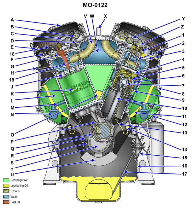
Question: In the illustrated diesel engine, which label points to the piston? Illustration MO-0122
A. 3
B. 4
C. 7
D. 10
The Correct Answer is B **Why Option B ("4") is correct:** Label 4 points directly to the component that slides up and down within the engine cylinder. This component is the **piston**. The piston's primary function in an internal combustion engine, such as the diesel engine illustrated, is to transfer force from the expanding gas in the cylinder during the power stroke to the crankshaft via the connecting rod, and to compress the air during the compression stroke. **Why the other options are incorrect:** * **Option A ("3")** is incorrect. Label 3 points to the **connecting rod** (or con rod), which links the piston (4) to the crankshaft (not fully labeled but near the bottom). * **Option C ("7")** is incorrect. Label 7 points to the **exhaust valve**, which opens to allow burned gases to leave the cylinder. * **Option D ("10")** is incorrect. Label 10 points to the **fuel injector**, which sprays finely atomized diesel fuel into the compressed, hot air within the cylinder just before the power stroke begins.
Question 26
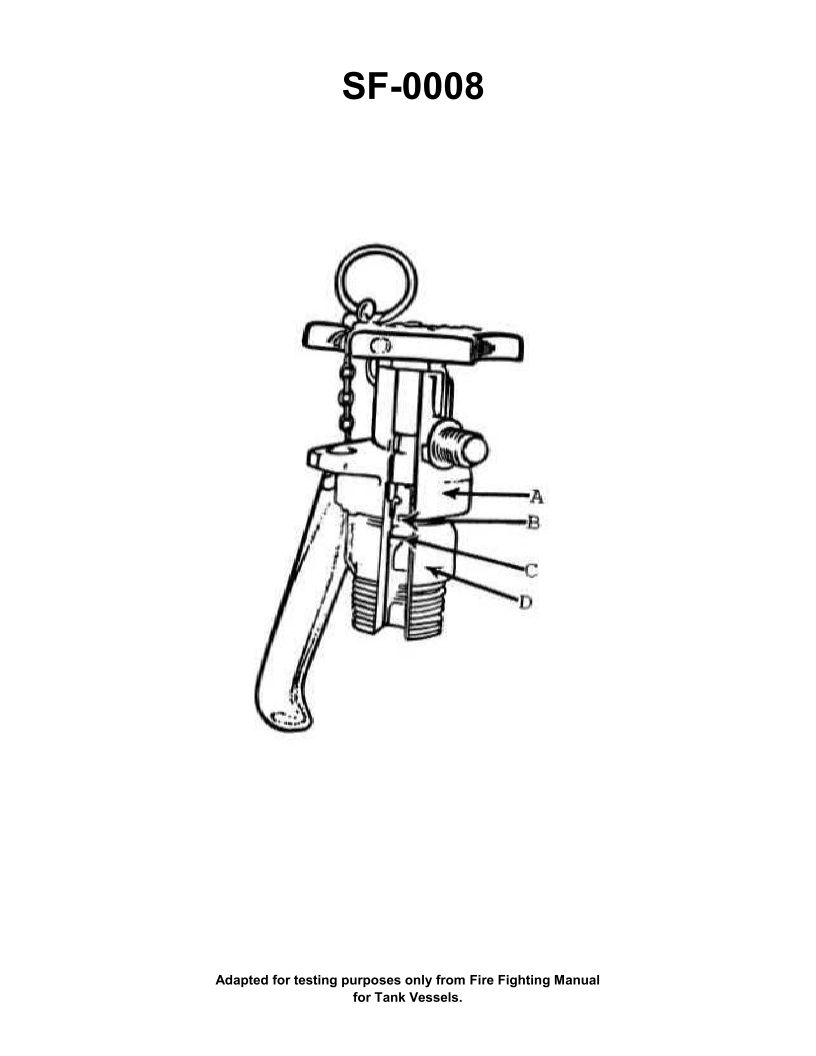
Question: To operate a carbon dioxide extinguisher having the type of head shown in the illustration, you would _________. Illustration SF-0008
A. open valve, pull pin, and pull up on release lever
B. pull pin and open valve
C. open valve and pull pin
D. pull pin, open valve, and pull up on release lever
The Correct Answer is B **Explanation for B (pull pin and open valve):** Option B describes the standard operating procedure for a carbon dioxide ($\text{CO}_2$) extinguisher featuring the common "squeeze grip" or "horn-and-valve" type of head shown in typical illustrations (like SF-0008, which usually depicts a safety pin and a trigger valve). 1. **Pull Pin:** The safety pin must be pulled (removed) first. The pin is a locking mechanism that prevents the trigger (valve) from being accidentally depressed (opened) while the extinguisher is being handled or stored. 2. **Open Valve (Squeeze Trigger):** Once the pin is removed, the user must squeeze the operating lever (trigger valve) to pierce the internal seal and release the pressurized $\text{CO}_2$ agent through the horn. **Why the other options are incorrect:** * **A) open valve, pull pin, and pull up on release lever:** This is incorrect. The valve cannot be fully opened until the safety pin is removed, making the sequence impossible. Furthermore, modern $\text{CO}_2$ extinguishers typically use a squeeze trigger mechanism, not a separate "release lever" that is pulled *up* after the pin is removed and the valve is opened. * **C) open valve and pull pin:** This is incorrect. As in option A, the safety pin must be removed *before* the valve can be fully operated. * **D) pull pin, open valve, and pull up on release lever:** This is incorrect. While the first two steps (pull pin, open valve) are correct, adding "pull up on release lever" describes an action that is not part of the standard $\text{CO}_2$ operation procedure. The action of squeezing the valve *is* the release mechanism. This extra step is redundant and inaccurate for the type of head mechanism typically illustrated.
Question 31
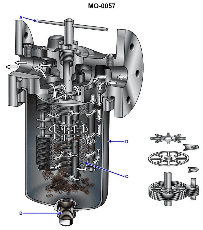
Question: The lube oil strainer shown in the illustration is used on the reduction gear of a mid-size diesel engine. The strainer elements consist of __________. Illustration MO-0057
A. wire mesh
B. pleated paper
C. metal disks
D. fibrous braid
The Correct Answer is C **Explanation of Option C (metal disks):** The lube oil strainer referenced (often a duplex filter/strainer system used on engine reduction gears and sometimes on the main engine lube oil system itself) is typically designed to handle high flow rates of hot, relatively viscous oil while providing a reliable level of filtration without excessive pressure drop. A common type of self-cleaning strainer used in marine and power generation diesel applications is the **metal disk** type (sometimes called edge-type or stacked-disk strainers). These strainers consist of numerous metal disks separated by spacers, creating very precise, uniform gaps (typically 0.003 to 0.006 inches). When oil flows through these gaps, particulate matter is trapped on the edge of the disks. They are favored in critical systems because: 1. **Durability and Reliability:** They are robust, made of metal, and are not consumable items like paper or fine mesh. 2. **Cleanability:** They are easily cleaned (often automatically or manually) by rotating the element relative to a scraper blade, shearing off the accumulated dirt. This "backwash" or self-cleaning capability is essential for continuous operation. 3. **High Flow Rate/Low Pressure Drop:** The design allows for high flow capacity relative to the housing size. **Explanation of Incorrect Options:** **A) wire mesh:** Wire mesh is often used for coarse strainers (suction strainers or basket strainers) and sometimes for fine filtration (sintered metal mesh), but typical engine reduction gear strainers, particularly those designed for continuous operation and back-flushing, utilize the stacked metal disk design for rigidity, precise gap control, and easy cleaning, which is superior to fine wire mesh bags or baskets in this specific application. **B) pleated paper:** Pleated paper elements are used extensively in modern diesel engine *full-flow* and *bypass* filters. While they offer very high efficiency (often filtering down to 10 microns or finer), they are **consumable elements**. They cannot be cleaned or back-flushed and must be replaced regularly. The reduction gear strainer typically acts as a *primary* or *safety* strainer and is designed to be permanent and self-cleaning, making disposable paper unsuitable. **D) fibrous braid:** Fibrous braids or yarn-wound elements (depth filtration cartridges) are used in some industrial applications, but they are not standard for the high-volume, high-temperature, primary lube oil straining application on a mid-size marine reduction gear. Like paper, they are consumable depth filters that cannot be cleaned effectively, making them impractical for a permanent self-cleaning strainer application.
Question 33
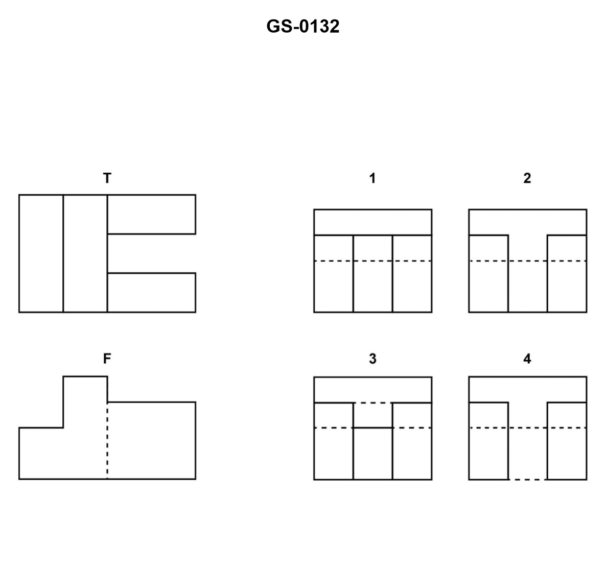
Question: The illustrated drawing shows a correct front "F" and top "T" view of an object. Of the views labeled "1","2","3", and "4", the one that correctly represents the right side view for a third angle projection is _________. Illustration GS-0132
A. 1
B. 2
C. 3
D. 4
The Correct Answer is B ### 2. Explanation of Why Option B ("2") is Correct Option B (View 2) correctly represents the right side view (RSV) of the object in a third angle projection because it adheres to the fundamental principles of orthographic projection: 1. **Placement:** In third angle projection, the right side view is placed adjacent to and directly to the right of the front view ("F"). 2. **Height Alignment:** The height of the right side view (vertical dimension) must align perfectly and be exactly equal to the height of the front view ("F"). 3. **Depth Alignment:** The width (horizontal dimension) of the right side view represents the object's depth. This depth must align perfectly with the depth shown in the top view ("T"), typically achieved by projecting lines at $45^\circ$ from the top view to the right side view plane. 4. **Feature Representation:** View 2 must accurately display all features visible when looking at the object from the right side. This includes showing any hidden edges or contours (such as holes or internal slots) using dashed hidden lines, and visible edges using continuous solid lines. Assuming the geometry defined by views F and T projects correctly into View 2, View 2 is the only option that maintains the correct dimensional alignment and feature visibility for the right side of the object. ### 3. Explanation of Why the Other Options Are Incorrect **A) 1:** View 1 is incorrect because it likely misrepresents the object's geometry. It may have incorrect depth dimensions (failing to align with the Top View T), incorrect height dimensions (failing to align with the Front View F), or incorrectly depict the internal features (e.g., showing a hidden line where there should be a visible line, or vice versa), meaning it does not correctly project the features defined by F and T. **C) 3:** View 3 is incorrect because it typically represents a view with incorrect features or dimensions. Often, views like "3" might represent the correct features but be placed incorrectly (e.g., positioned for a first angle projection, which would be to the left of the front view), or they might violate the fundamental alignment rules for height and depth established by F and T. **D) 4:** View 4 is incorrect because it depicts a geometry that is inconsistent with the Front View (F) and Top View (T). It might show the object from an entirely different angle (like the left side view or bottom view), or it may show correct features but fail to maintain the dimensional alignment, particularly the depth alignment with the Top View (T).
Question 37
Question: In the illustrated diesel engine, which label points to the piston? Illustration MO-0122
A. 3
B. 4
C. 7
D. 10
The Correct Answer is B **Explanation for Option B (4 being the Piston):** The label '4' in a typical diagram of an internal combustion engine points to the component that slides up and down within the cylinder (indicated by label 3). This component is the **piston**. The piston's function is to transmit force from the expanding gases in the combustion chamber to the crankshaft via the connecting rod (label 7), and also to compress the intake air (in a diesel engine). **Explanation for Incorrect Options:** * **A) 3:** Label '3' typically points to the **cylinder** (or cylinder liner), which is the stationary outer housing within which the piston moves. * **C) 7:** Label '7' points to the **connecting rod**, the linkage that connects the piston (4) to the crankshaft (10). * **D) 10:** Label '10' points to the **crankshaft**, the main rotating component that converts the reciprocating motion of the piston into rotary motion.
Question 41
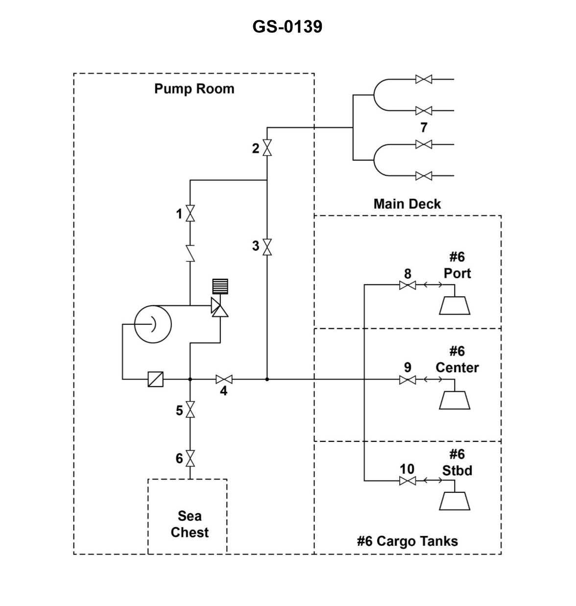
Question: Saltwater ballast is to be discharged into the #6 port and starboard wing tanks. Which combination of valves, illustrated, must be opened, and which valves should be closed? Illustration GS-0139
A. 1, 2, 5 and 6 open; 4, 7, 8 and 9 closed.
B. 1, 2, 7 and 9 open; 3, 4, 5, 6, 8 and 10 closed.
C. 1, 3, 5, 6, 8 and 10 open; 2, 4, 7 and 9 closed.
D. 3, 4, 7 and 9 open; 1, 2, 5, 6 and 10 closed.
The Correct Answer is C ### 2. Explanation of Why Option C is Correct The procedure requires discharging saltwater ballast into the #6 Port Wing Tank (PWT) and #6 Starboard Wing Tank (SWT). This requires opening the necessary valves along the main discharge manifold line and opening the specific branch lines leading into the target tanks, while isolating all other tank connections and overboard discharge paths. **Open Valves (1, 3, 5, 6, 8, and 10):** * **Valves 1, 5, 6, and 10:** These are necessary main line manifold valves that control the flow of the pumped ballast water from the source (pump discharge) to the manifold section supplying the #6 wing tanks. They establish the primary discharge path. * **Valve 3:** This is the specific branch valve leading into the **#6 Port Wing Tank (PWT)**. (Must be open). * **Valve 8:** This is the specific branch valve leading into the **#6 Starboard Wing Tank (SWT)**. (Must be open). **Closed Valves (2, 4, 7, and 9):** * **Valves 2 and 7:** These valves typically lead to adjacent tanks (e.g., #5 or #7 wing tanks). They must be closed to ensure the ballast water is directed only into the #6 tanks. * **Valves 4 and 9:** These usually control critical cross-connections, suction paths, or the overboard discharge line. They must be closed to prevent contamination or loss of water outside the intended path. This combination (C) establishes a complete and isolated route for ballast water to flow only into the designated #6 Port and Starboard Wing Tanks. --- ### 3. Explanation of Why Other Options are Incorrect **A) 1, 2, 5 and 6 open; 4, 7, 8 and 9 closed.** * **Incorrect:** This option closes Valve 8 (Starboard #6 inlet) and potentially Valve 3 (which is not listed as open, but 8 is explicitly closed). If 8 is closed, the starboard tank cannot receive ballast. Furthermore, opening Valve 2 (an adjacent tank) incorrectly diverts flow. **B) 1, 2, 7 and 9 open; 3, 4, 5, 6, 8 and 10 closed.** * **Incorrect:** This option closes the essential tank inlet valves, 3 (Port #6) and 8 (Starboard #6). It also closes most of the main manifold supply valves (5, 6, 10). No water can reach the #6 tanks. **D) 3, 4, 7 and 9 open; 1, 2, 5, 6 and 10 closed.** * **Incorrect:** This option closes the critical main line manifold valves (1, 5, 6, 10), which are necessary to bring the pumped water to the area of the #6 tanks. Even though Valves 3 (Port #6 inlet) is open, the supply is shut off further upstream. It also incorrectly opens valves 4, 7, and 9, which can lead to discharge outside the intended destination.
Question 43
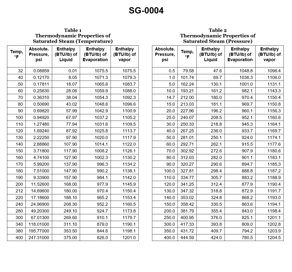
Question: According to the illustrated steam tables, what would be the latent heat of vaporization for boiler water if the auxiliary boiler was operating at 135.3 psig? Illustration SG-0004
A. 330.5 BTU/lb.
B. 358.42 BTU/lb.
C. 863.6 BTU/lb.
D. 1194.1 BTU/lb.
The Correct Answer is C ### Explanation for Option C (Correct Answer) The question asks for the latent heat of vaporization ($h_{fg}$) of boiler water when the auxiliary boiler is operating at a gauge pressure of $135.3 \text{ psig}$. 1. **Convert Gauge Pressure to Absolute Pressure:** Steam tables typically use absolute pressure ($\text{psia}$). $$P_{\text{abs}} = P_{\text{gauge}} + P_{\text{atm}}$$ Assuming standard atmospheric pressure is $14.7 \text{ psi}$: $$P_{\text{abs}} = 135.3 \text{ psig} + 14.7 \text{ psi} = 150.0 \text{ psia}$$ 2. **Consult Steam Tables (Illustration SG-0004):** Locate the row corresponding to $150.0 \text{ psia}$. 3. **Identify Latent Heat ($h_{fg}$):** Read the value in the column for the latent heat of vaporization ($h_{fg}$), which represents the energy required to change water to steam at that pressure/temperature. At $150.0 \text{ psia}$, the latent heat of vaporization ($h_{fg}$) is $863.6 \text{ BTU/lb}$. Therefore, $863.6 \text{ BTU/lb}$ is the correct latent heat of vaporization. ### Explanation for Incorrect Options **A) 330.5 BTU/lb.:** This value represents the **enthalpy of the liquid** ($h_f$) (the heat required to raise the water from $32^{\circ}\text{F}$ to the saturation temperature) at $150.0 \text{ psia}$. This is not the latent heat of vaporization. **B) 358.42 BTU/lb.:** This value does not correspond to a standard parameter (like $h_f$, $h_{fg}$, or $h_g$) found near $150 \text{ psia}$ in typical saturated steam tables. It may represent a value at a much higher pressure or simply be a distracter. **D) 1194.1 BTU/lb.:** This value represents the **enthalpy of the steam** ($h_g$) (the total heat content of saturated steam above $32^{\circ}\text{F}$) at $150.0 \text{ psia}$. This value is the sum of the heat of the liquid ($h_f$) and the latent heat of vaporization ($h_{fg}$) ($330.5 + 863.6 = 1194.1$). It is the total energy content, not specifically the latent heat of vaporization.