Pass Your Coast Guard Licensing Exams!
Study offline, track your progress, and simulate real exams with the Coast Guard Exams app
QMED04 - Boiler Technician-Watertender
6 images
Question 2
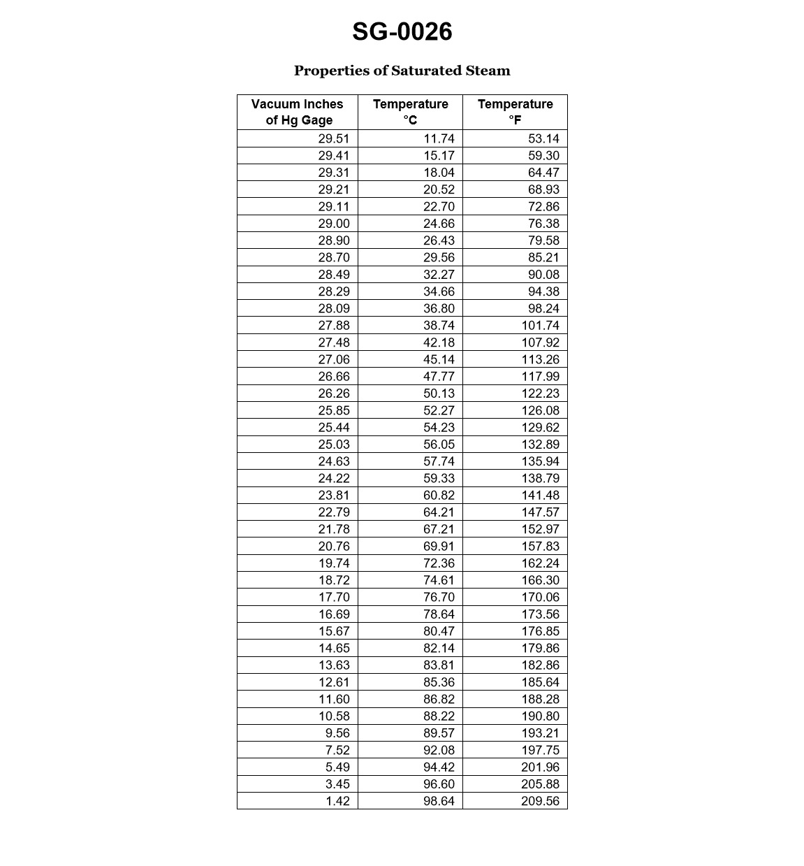
Question: While underway on a steamship, the main condenser is operating under a 28.09 "Hg vacuum gauge. According to the illustrated properties of saturated steam table, how much condensate depression would there be if the condensate temperature leaving the main condenser hot well is 96.0°F? Illustration SG-0026
A. 1.83°F
B. 2.24°F
C. 8.71°F
D. 70.15°F
The Correct Answer is B ### 1. Explanation for Option B (2.24°F) The required value is the **condensate depression**, which is the difference between the saturation temperature corresponding to the condenser vacuum and the actual temperature of the condensate leaving the hotwell. **Formula:** $$\text{Condensate Depression} = T_{\text{saturation}} - T_{\text{condensate}}$$ **Step 1: Determine the Absolute Pressure in the Condenser.** The condenser vacuum is given as $28.09 \text{ "Hg (gauge)}$. To use the saturated steam table (which correlates saturation temperature to absolute pressure), we must first find the absolute pressure. Assuming standard atmospheric pressure (for typical maritime/engineering contexts) is $29.92 \text{ "Hg}$: $$\text{Absolute Pressure} = \text{Atmospheric Pressure} - \text{Vacuum Gauge Reading}$$ $$\text{Absolute Pressure} = 29.92 \text{ "Hg} - 28.09 \text{ "Hg}$$ $$\text{Absolute Pressure} = 1.83 \text{ "Hg}$$ **Step 2: Find the Saturation Temperature ($T_{\text{saturation}}$).** Using the saturated steam table (SG-0026) for an absolute pressure of $1.83 \text{ "Hg}$: The table shows that the saturation temperature corresponding to $1.83 \text{ "Hg (absolute)}$ is $98.24^{\circ}\text{F}$. $$T_{\text{saturation}} = 98.24^{\circ}\text{F}$$ **Step 3: Calculate the Condensate Depression.** The actual condensate temperature ($T_{\text{condensate}}$) is given as $96.0^{\circ}\text{F}$. $$\text{Condensate Depression} = 98.24^{\circ}\text{F} - 96.0^{\circ}\text{F}$$ $$\text{Condensate Depression} = 2.24^{\circ}\text{F}$$ Therefore, the condensate depression is $2.24^{\circ}\text{F}$. --- ### 2. Explanation of Why Other Options are Incorrect **A) 1.83°F** This value is the absolute pressure in the condenser ($1.83 \text{ "Hg}$), not the temperature difference. This option is incorrect because it confuses pressure units with temperature units. **C) 8.71°F** This result is obtained if an incorrect saturation temperature is used. If one mistakenly used a saturation temperature corresponding to a higher vacuum or made a calculation error, this result could arise, but it does not match the thermodynamic properties provided by the pressure $1.83 \text{ "Hg absolute}$. (For example, $104.71^{\circ}\text{F} - 96.0^{\circ}\text{F} = 8.71^{\circ}\text{F}$, where $104.71^{\circ}\text{F}$ is the saturation temperature corresponding to approximately $2.24 \text{ "Hg absolute}$). **D) 70.15°F** This value is far too large for a typical condensate depression. This error likely results from using a completely incorrect reference point, such as calculating the difference between the condensate temperature and $32^{\circ}\text{F}$ or subtracting the vacuum gauge reading from the saturation temperature, which results in a meaningless physical quantity for this calculation.
Question 37
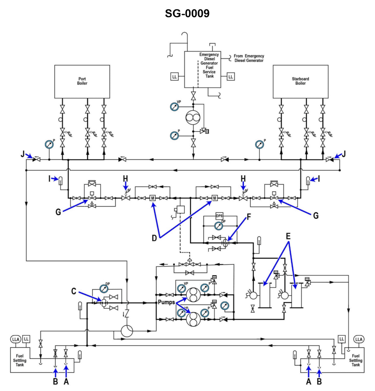
Question: Why are two fuel oil heaters "E" provided in the fuel oil system shown in the illustration? Illustration SG-0009
A. To allow fuel of different temperatures to be provided to each boiler.
B. To provide a backup in case one of the heaters becomes inoperable.
C. Two heaters are necessary when both boilers steam at full load.
D. Each heater supplies fuel to a different boiler.
The Correct Answer is B. Option B is correct because marine and power plant systems, especially those dealing with critical fluids like fuel oil, are designed with redundancy for reliability and safety. Fuel oil must be heated to the correct viscosity for proper atomization and combustion in the boiler burners. If the single operational fuel oil heater fails (due to leakage, scaling, or control failure), the standby heater allows operations to continue without interruption. Providing two heaters ensures that the required heating duty can always be maintained, fulfilling the critical function of providing a backup in case one of the heaters becomes inoperable. **Why the other options are incorrect:** * **A) To allow fuel of different temperatures to be provided to each boiler.** This is incorrect. Both boilers are typically supplied with the same type of fuel oil and require it to be heated to the same temperature (the temperature needed for optimal viscosity and combustion) before it reaches the burners. * **C) Two heaters are necessary when both boilers steam at full load.** This is incorrect. A single, properly sized fuel oil heater is designed to handle the maximum flow rate and heating requirement needed when both boilers are steaming at full load. The second unit is a standby unit, not a capacity booster required for normal operations. * **D) Each heater supplies fuel to a different boiler.** This is incorrect. Typically, the heaters operate in parallel, drawing from the same suction line and feeding into the common discharge header, which then supplies both boilers. They are arranged as duty/standby, not dedicated supply units.
Question 48
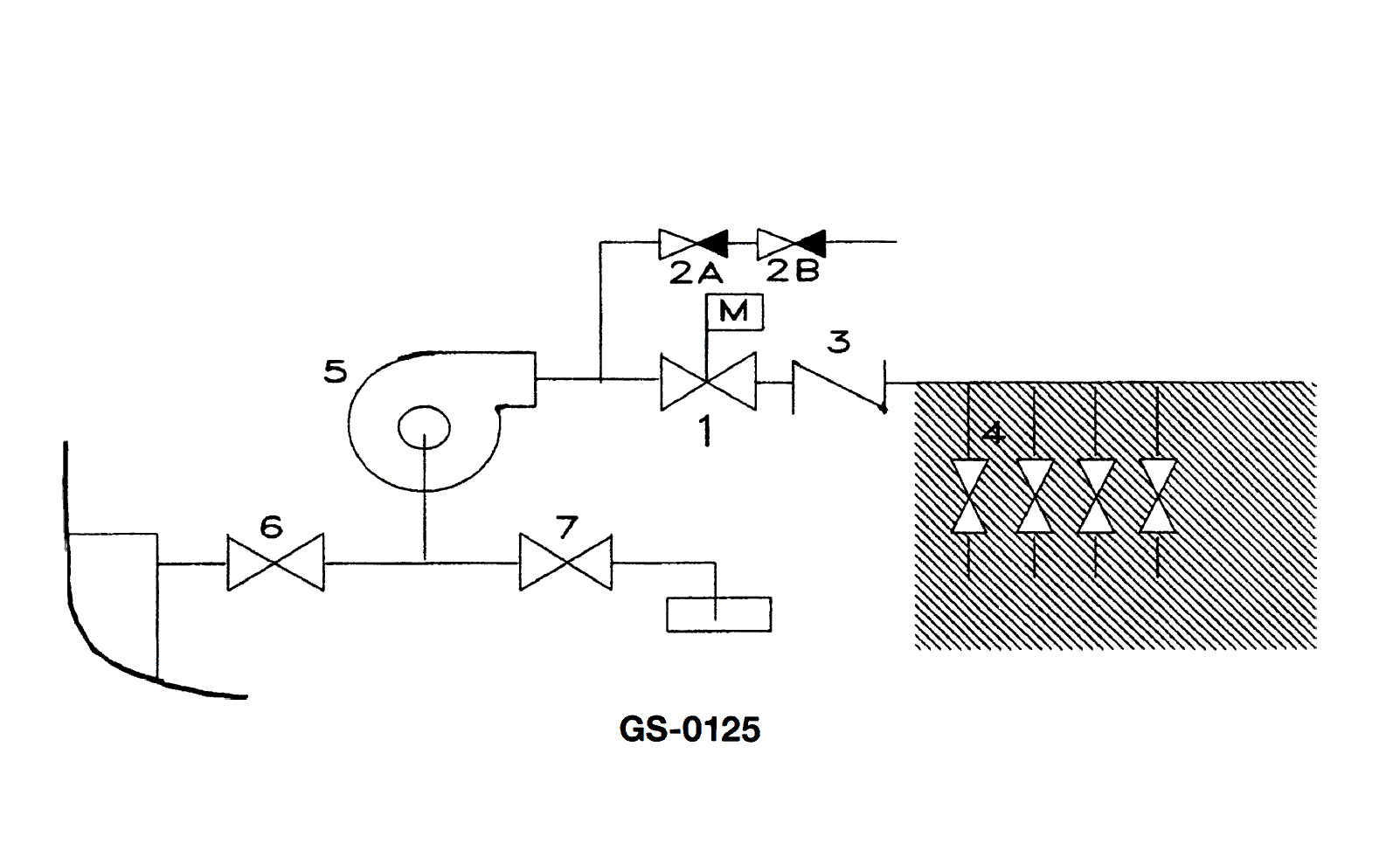
Question: Item 4 shown in the illustration represents a __________. Illustration GS-0125
A. manifold
B. suction line
C. bilge system
D. vacuum branch line
The Correct Answer is A **Explanation for A (manifold):** In marine engineering or process systems (which illustrations like GS-0125 often depict, focusing on piping schematics), a manifold is a pipe or chamber having several outlets or inlets that serves to divide or combine fluid flow. Item 4, based on standard illustrations of fluid handling systems, typically represents a section where multiple lines converge into a common header (inlet manifold) or diverge from a common header (distribution manifold). This component is designed to manage the flow control and routing for several separate pipelines, which is the defining function of a manifold. **Explanation for Incorrect Options:** * **B) suction line:** A suction line is a single pipe that draws fluid into a pump or system. While lines connected to the manifold may be suction lines, the manifold (Item 4) itself is the distributing/collecting device, not just a single flow line. * **C) bilge system:** A bilge system is the overall network of piping, pumps, and valves designed to remove water from the lower compartments (bilges) of a vessel. Item 4 is a specific component *within* a larger fluid system (which could be the bilge system), but it is not the entire system itself. * **D) vacuum branch line:** A vacuum branch line is a specific type of piping used to draw a vacuum. Like a suction line, this describes a single pipe's function. The manifold (Item 4) is the central fitting that connects multiple such lines, rather than being a single branch line.
Question 60
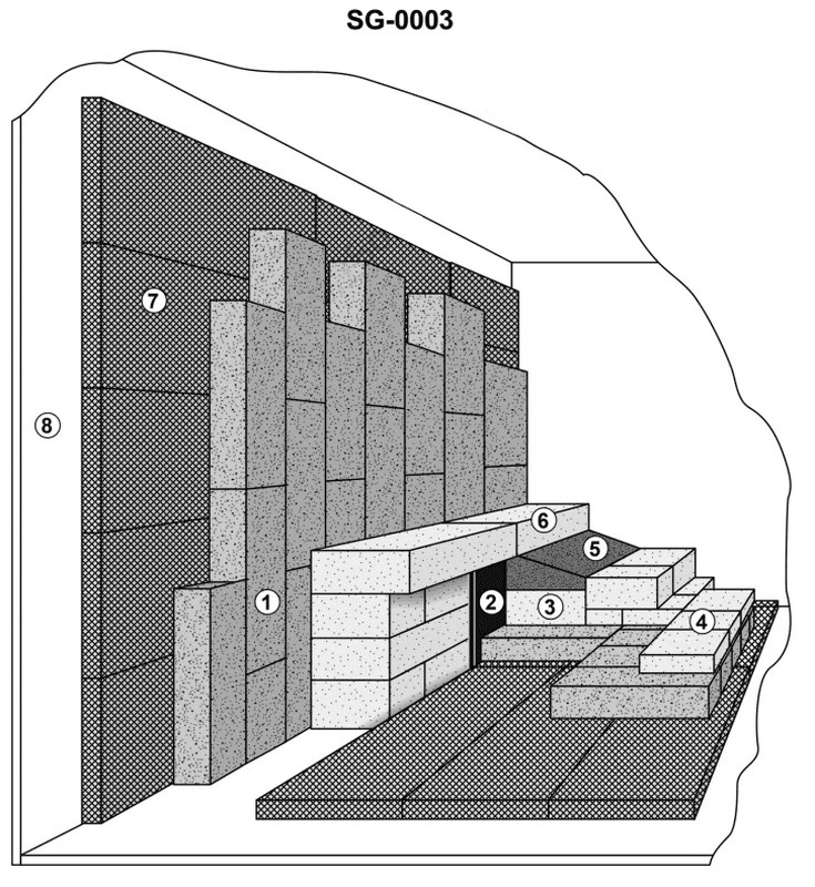
Question: Which of the following labeled items of the illustrated section of boiler refractory represents the insulating block? Illustration SG-0003
A. 1
B. 3
C. 4
D. 7
The Correct Answer is D **Why option D ("7") is correct:** Option D refers to item 7 in the illustration. Item 7 typically represents the layer furthest away from the hot combustion gases and closest to the boiler casing (or tube wall/casing). In standard boiler refractory construction, the layers are arranged based on thermal duty: a hot face layer (usually dense/abrasion-resistant firebrick or plastic refractory), a backup insulation layer (usually insulating firebrick or block), and then, often, a final layer of high-efficiency **insulating block** or blanket, which provides the majority of the heat savings and minimizes heat loss to the environment. Item 7 is positioned correctly as this final, external layer of high-efficiency insulation, often referred to as the insulating block or board. **Why the other options are incorrect:** * **A) 1:** Item 1 is typically the outer steel casing or boiler shell, which provides structural integrity, not the insulating block itself. * **B) 3:** Item 3 is usually positioned as the layer directly against the hot face refractory (e.g., item 4), representing the backup insulation layer (Insulating Fire Brick - IFB), which is different from the high-density insulating block (item 7) often used externally. * **C) 4:** Item 4 is the innermost layer, known as the hot face refractory (often firebrick or castable/plastic refractory), designed to withstand the highest temperatures and protect the underlying structure. It is not the insulating block.
Question 61
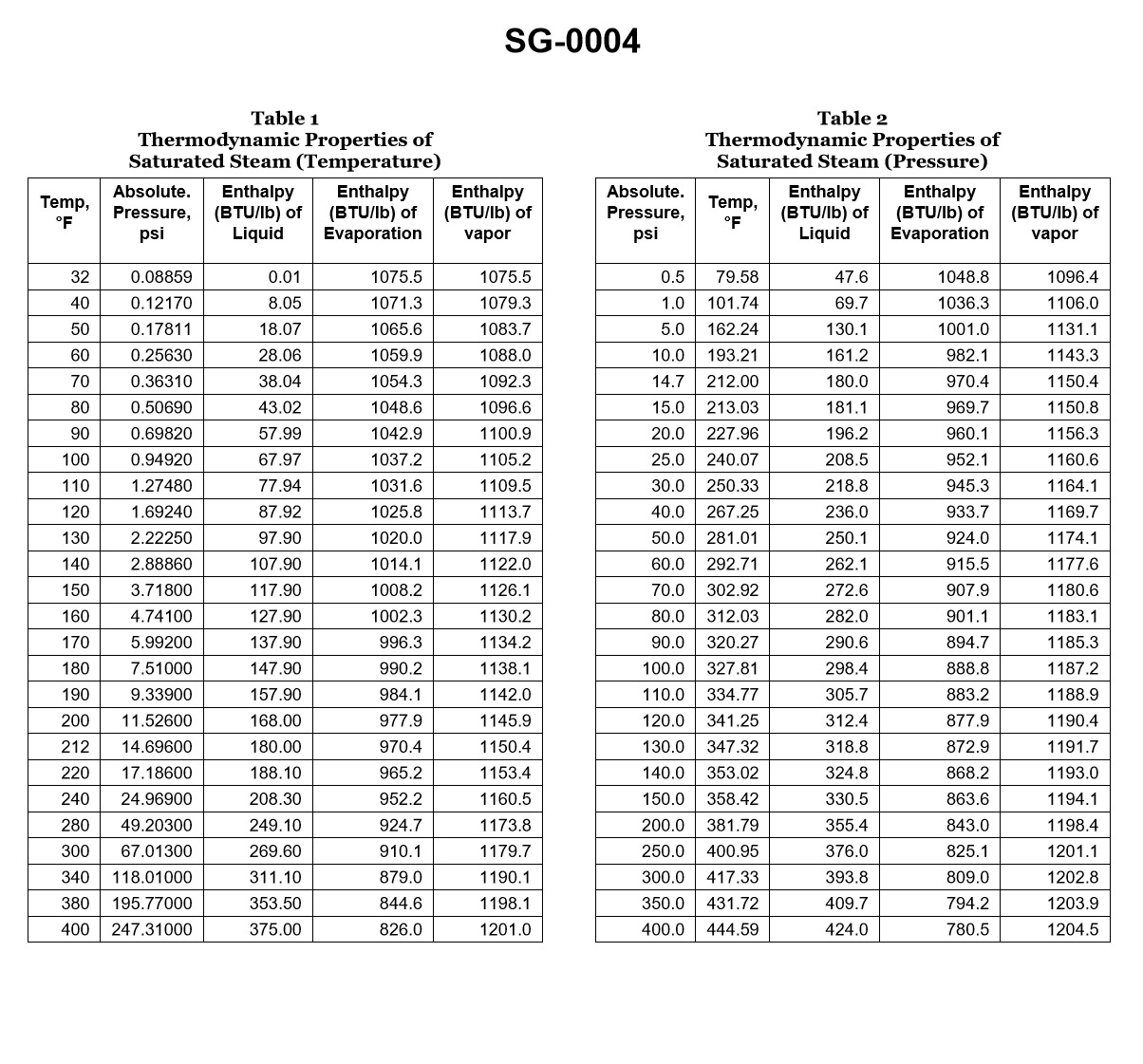
Question: According to the illustrated steam tables, what would be the superheater outlet temperature if saturated steam at 400 psia was elevated 192.83°F? Illustration SG-0004
A. 192.83°F
B. 247.31°F
C. 444.59°F
D. 637.42°F
The Correct Answer is D **Explanation for Option D (637.42°F):** The problem asks for the superheater outlet temperature ($T_{out}$) given the initial saturated steam pressure and the temperature elevation (superheat). 1. **Determine the Saturation Temperature ($T_{sat}$):** We must first find the temperature at which water boils (saturates) at the given pressure, 400 psia, using the steam tables (Illustration SG-0004). * Referring to the saturated steam tables for 400 psia: $T_{sat} = 444.59^\circ\text{F}$. 2. **Calculate the Superheater Outlet Temperature ($T_{out}$):** The superheater elevates the steam temperature by the given amount (superheat). The outlet temperature is the saturation temperature plus the temperature elevation. * Temperature Elevation ($\Delta T$) = $192.83^\circ\text{F}$ * $T_{out} = T_{sat} + \Delta T$ * $T_{out} = 444.59^\circ\text{F} + 192.83^\circ\text{F}$ * $T_{out} = 637.42^\circ\text{F}$ Therefore, the superheater outlet temperature is $637.42^\circ\text{F}$. **Explanation for Incorrect Options:** * **A) 192.83°F:** This is the value of the temperature elevation (the amount of superheat) itself, not the final outlet temperature. * **B) 247.31°F:** This value is likely the saturation temperature corresponding to a different, lower pressure (approximately 30 psia) and is irrelevant to the calculation at 400 psia. * **C) 444.59°F:** This is the saturation temperature ($T_{sat}$) of the steam at 400 psia. It represents the temperature *entering* the superheater, not the elevated temperature *exiting* it.
Question 68
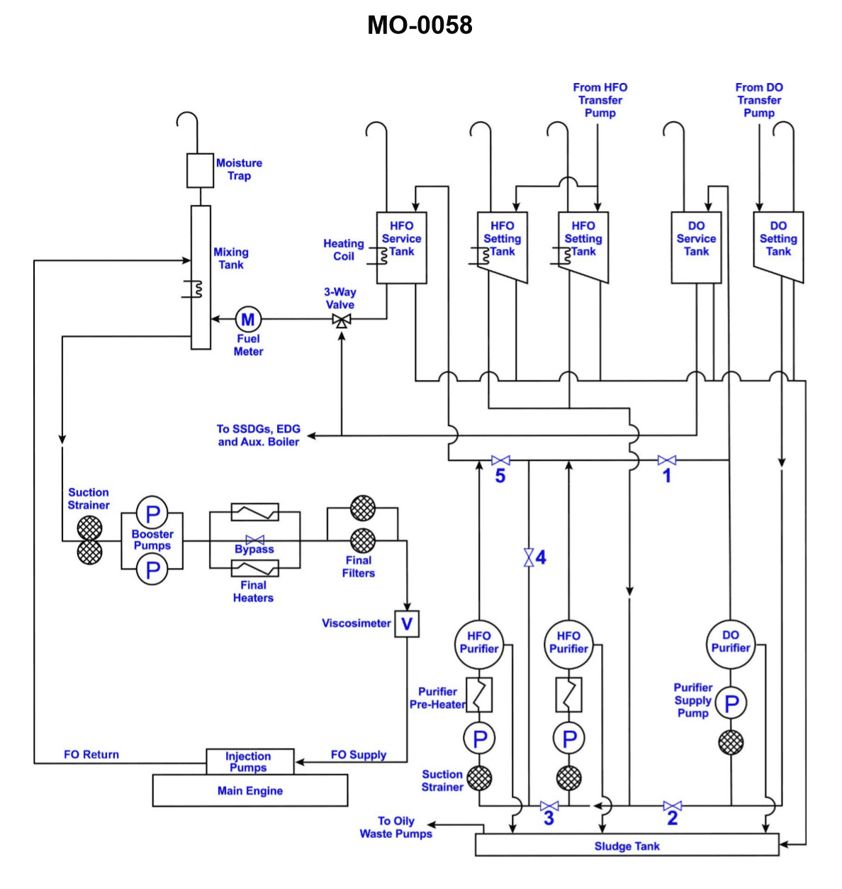
Question: Which of the tanks, shown in the illustration, supplies fuel to the emergency generator? Illustration MO-0058
A. Diesel Oil Service Tank
B. Diesel Oil Settling Tank
C. Diesel Oil Boiler Tank
D. Diesel Oil Booster Tank
The Correct Answer is A **Why Option A ("Diesel Oil Service Tank") is correct:** The Diesel Oil Service Tank (sometimes called the Day Tank) is specifically designed and positioned to supply readily usable, filtered fuel directly to the diesel engines, including the main engines and crucial auxiliary engines like the emergency generator. Because the emergency generator must be capable of starting immediately and reliably under blackout conditions, it requires a dedicated, clean fuel supply located near the generator, which is the function of the Service Tank in the fuel oil system layout (as typically depicted in marine or stationary power plant illustrations like MO-0058). **Why the other options are incorrect:** * **B) Diesel Oil Settling Tank:** The Settling Tank's primary function is to receive bulk fuel, allow heavier impurities and water to separate out through gravity over time, and prepare the fuel for further purification (e.g., by a purifier/centrifuge). It is an intermediate storage and treatment stage, not the direct supply source for the operating generator. * **C) Diesel Oil Boiler Tank:** This term is generally non-standard in a typical diesel fuel system layout. Boilers are typically fired by Heavy Fuel Oil (HFO) or Marine Gas Oil (MGO), and the tank supplying the boiler would be referred to as the HFO or MGO Service Tank, separate from the tanks supplying the emergency diesel generator. * **D) Diesel Oil Booster Tank:** This term is not standard terminology for a component within the main fuel storage or supply path. A "booster" function typically refers to a pump (a booster pump) used to increase pressure, not a storage tank.