Pass Your Coast Guard Licensing Exams!
Study offline, track your progress, and simulate real exams with the Coast Guard Exams app
QMED03 - Oiler
17 images
Question 1
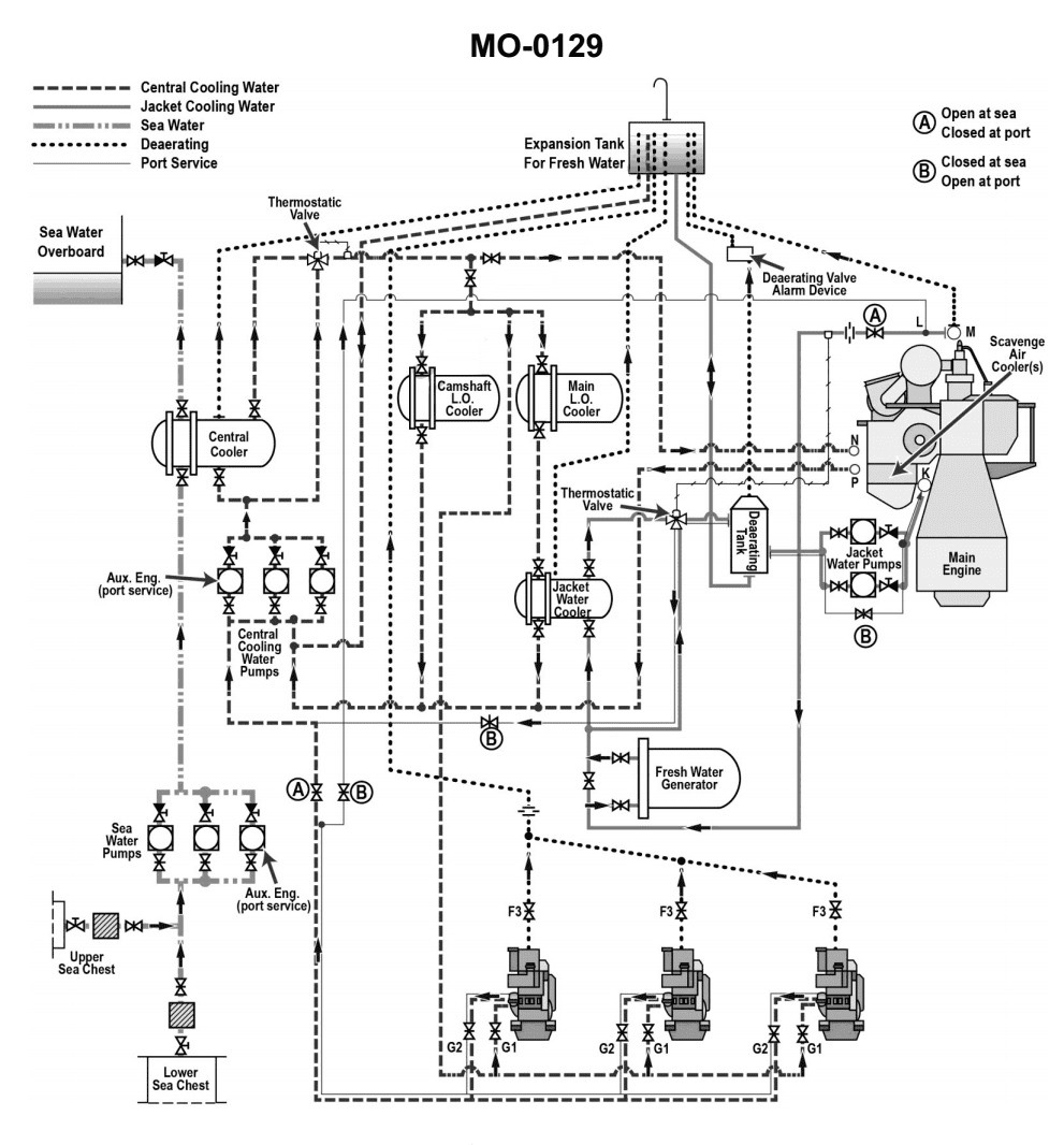
Question: According to the illustrated main and auxiliary diesel engine cooling water systems diagram, which of the following heat exchangers are connected directly in series with one another? Illustration MO-0129
A. Jacket water cooler and scavenge air cooler(s)
B. Camshaft lube oil cooler and jacket water cooler
C. Camshaft lube oil cooler and scavenge air cooler(s)
D. Lube oil cooler and jacket water cooler
The Correct Answer is D ### Explanation for Option D (Correct Answer) Option D is correct because in most standard marine main diesel engine cooling water system diagrams (like the typical configurations illustrated in diagrams such as MO-0129), the **Lube Oil Cooler (or Main Engine Lube Oil Cooler)** and the **Jacket Water Cooler (or High Temperature [HT] Fresh Water Cooler)** are designed to be connected directly in series on the *freshwater side* (HT circuit). The typical flow is: 1. Engine Jacket Water (HT circuit) leaves the engine cylinder jackets. 2. It flows directly to the **Jacket Water Cooler** where it rejects heat to the Low Temperature (LT) circuit (seawater or LT central cooler circuit). 3. The cooled Jacket Water then flows directly through the **Lube Oil Cooler** to pick up the heat rejected by the main engine lube oil before returning to the engine circulation pumps. Alternatively, some systems place the lube oil cooler first, but they are almost always placed sequentially (in series) within the HT circuit to manage the overall heat balance and maximize cooling efficiency before the jacket water returns to the engine. ### Explanation for Incorrect Options **A) Jacket water cooler and scavenge air cooler(s)** * **Incorrect:** These two components operate in different cooling circuits. The **Jacket Water Cooler** is in the High Temperature (HT) circuit. The **Scavenge Air Cooler(s)** is/are typically cooled by the Low Temperature (LT) circuit (which is often a separate centralized cooler circuit or direct seawater). They are therefore connected in parallel relative to the engine's main cooling requirements, not in series on the same HT line. **B) Camshaft lube oil cooler and jacket water cooler** * **Incorrect:** The **Camshaft Lube Oil Cooler** handles a minor, isolated cooling load. This cooler is almost always connected in parallel with the main HT system flow, often taking cooled jacket water *after* it has exited the main Jacket Water Cooler and returning it directly to the system pump suction or back into the main HT return line, but not directly in series with the main flow path of the Jacket Water Cooler itself. **C) Camshaft lube oil cooler and scavenge air cooler(s)** * **Incorrect:** These two components are cooled by two different circuits (Camshaft Cooler typically by HT or sometimes LT water, and Scavenge Air Cooler always by LT water). They are never connected directly in series with each other.

Question 3
Question: As shown in the illustrated wound-rotor induction motor, how is the direction of rotation of the motor reversed? Illustration EL-0148
A. Any two of the "T1, T2, and T3" leads are reversed only.
B. Any two of the "M1, M2, and M3" leads are reversed only.
C. Any two of the "T1, T2, and T3" leads are reversed and any of the two "M1, M2, and M3" leads must be reversed as well.
D. It is not possible to change the direction of rotation of a wound-rotor induction motor.
The Correct Answer is A ### Explanation for Option A (Correct Answer) **Option A: Any two of the "T1, T2, and T3" leads are reversed only.** A wound-rotor induction motor, like a squirrel-cage induction motor, is an AC machine whose direction of rotation is determined by the phase sequence of the three-phase power supplied to the **stator windings**. The leads labeled "T1, T2, and T3" are the terminals connecting the external three-phase power source to the **stator**. To reverse the direction of rotation of any three-phase AC motor (including the wound-rotor type), the phase sequence of the voltage applied to the stator must be reversed. This is achieved by simply swapping any two of the three input power leads (T1, T2, or T3). This action reverses the direction of the rotating magnetic field, thereby reversing the motor's direction of rotation. ### Explanation for Incorrect Options **Option B: Any two of the "M1, M2, and M3" leads are reversed only.** The leads labeled "M1, M2, and M3" (or similar notation) typically refer to the connections associated with the **rotor windings** via slip rings, often connected to external resistors or shorting devices (rheostats) for speed control or high starting torque. The speed and torque characteristics of the motor are controlled by varying the external resistance in the rotor circuit, but the direction of rotation is solely determined by the rotating magnetic field created by the **stator**. Reversing the rotor connections will not reverse the rotation. **Option C: Any two of the "T1, T2, and T3" leads are reversed and any of the two "M1, M2, and M3" leads must be reversed as well.** As established, reversing the stator leads (T1, T2, T3) is sufficient to reverse the direction of rotation. Reversing both the stator and the rotor connections simultaneously would result in the magnetic field rotating in one direction (due to the stator change) and the rotor connections being reversed relative to the original setup. Since the direction is set by the stator field, and the rotor connections (M1, M2, M3) are generally shorted or connected to balanced resistors, reversing both sets of leads achieves no functional change in the direction of rotation compared to simply reversing the stator leads alone. The second reversal (M1, M2, M3) is unnecessary and irrelevant to reversing the rotation direction. **Option D: It is not possible to change the direction of rotation of a wound-rotor induction motor.** This is incorrect. Any standard three-phase induction motor, including the wound-rotor type, can have its direction of rotation easily reversed by changing the phase sequence of the stator power supply (reversing any two T leads).
Question 5
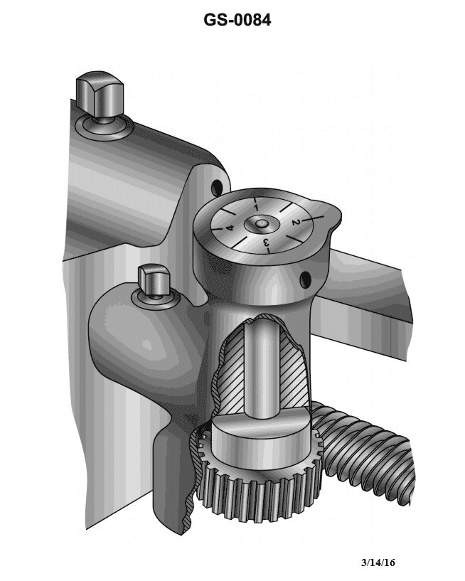
Question: To properly cut even numbered threads using the lathe thread dial indicator shown in the illustration, you should close the lathe split or half-nut on __________. Illustration GS-0084
A. any unnumbered half line
B. any line on the dial
C. odd numbered lines only
D. even numbered lines only
The Correct Answer is B ### Explanation of Why Option B is Correct **Option B) any line on the dial** is correct because of the relationship between the lead screw pitch and the thread dial mechanism when cutting even-numbered threads. When the threads per inch (TPI) being cut is an **even number**, the lathe's lead screw rotation aligns with the desired thread pitch regardless of which index mark (numbered line, odd line, or unnumbered half line) is used to engage the half-nut. This is because the movement of the carriage, relative to the lead screw, completes a full pitch cycle for every full rotation of the thread dial gear. Engaging on *any* line ensures the tool re-enters the groove correctly for the subsequent pass. ### Explanation of Why Other Options are Incorrect **Option A) any unnumbered half line:** While you can close the half-nut on an unnumbered half line when cutting even threads, this option is too restrictive. The rule for even threads allows engagement on *any* line, including the numbered lines. **Option C) odd numbered lines only:** This is incorrect. Odd-numbered lines (1, 3, 5, etc.) are safe to use for even threads, but limiting the choice only to these lines ignores the safe usage of even-numbered lines and unnumbered half lines. The restriction imposed by this option is unnecessary for even threads. (Note: Specific line requirements become critical when cutting odd threads or fractional TPI threads relative to the lead screw pitch.) **Option D) even numbered lines only:** This is incorrect. Just like Option C, this choice is too restrictive. For even TPI threads, all numbered lines (odd or even) and all unnumbered half lines are safe points for engagement.
Question 17
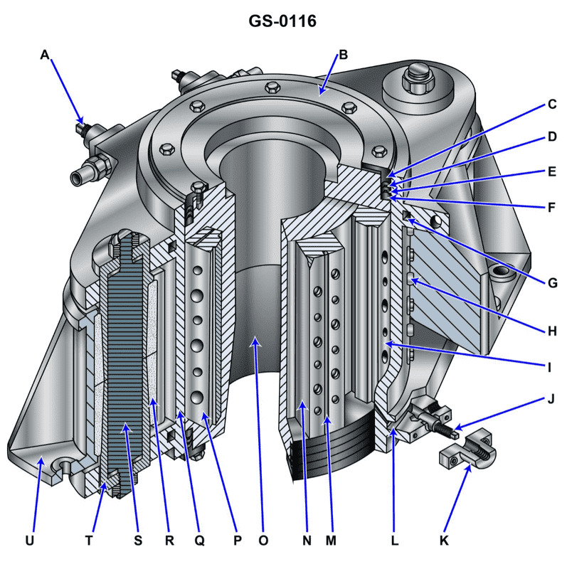
Question: The device shown in the illustration is a/an __________. Illustration GS-0116
A. mechanical shaft seal
B. vane type steering gear
C. diesel engine motor mount
D. oil scraper ring stuffing box for a crosshead engine
The Correct Answer is B **Why Option B ("vane type steering gear") is correct:** Illustration GS-0116 depicts a common type of modern marine steering apparatus. This device uses a rotor mounted directly on the rudder stock that moves within a fixed housing (stator). Pressurized hydraulic fluid is introduced into the chambers created by fixed vanes (on the stator) and moving vanes (on the rotor). By changing which chambers receive fluid pressure, the rotor is forced to rotate, thereby turning the rudder stock. This specific design is characteristic of a vane type steering gear (often referred to as a rotary vane steering gear) and is widely used on commercial vessels. **Why the other options are incorrect:** * **A) mechanical shaft seal:** A mechanical shaft seal is a component used to prevent leakage along a rotating shaft (e.g., a pump or propeller shaft). It typically consists of precision-machined stationary and rotating faces held together under pressure. The illustration clearly shows a large hydraulic actuator for angular movement, not a sealing mechanism. * **C) diesel engine motor mount:** A motor mount (or engine mount) is a passive structure or device (often incorporating rubber isolators) used to secure an engine to the ship's foundation while absorbing vibration. It does not contain hydraulic vanes or chambers for actuation. * **D) oil scraper ring stuffing box for a crosshead engine:** This component is part of the cylinder lubrication and sealing system of a large two-stroke crosshead diesel engine. It is positioned where the piston rod passes through the crankcase diaphragm plate. Its function is to scrape lubricating oil from the piston rod and prevent oil contamination. It is a linear sealing device, not a rotary hydraulic actuator.
Question 23
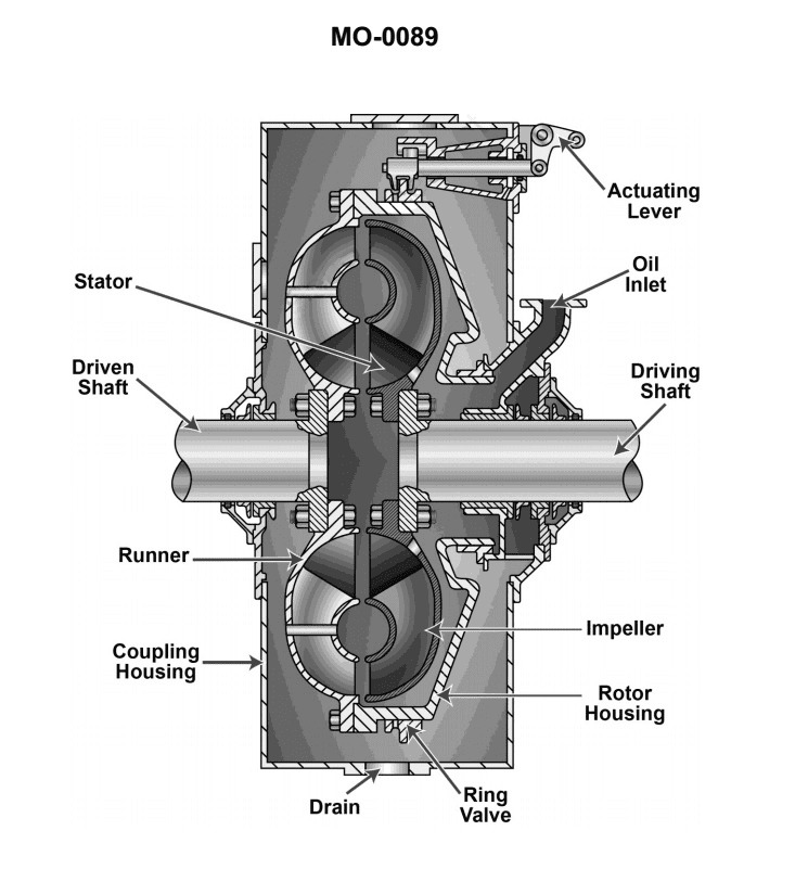
Question: What type of clutch is pictured in the illustration? Illustration MO-0089
A. Pneumatic
B. Electromagnetic
C. Mechanical
D. Hydraulic
The Correct Answer is D **Explanation for D (Hydraulic):** A hydraulic clutch utilizes fluid pressure (typically supplied by a master cylinder) to actuate the slave cylinder, which then moves the release bearing to engage or disengage the clutch. While Illustration MO-0089 itself is not provided, standard images depicting hydraulic clutches often show components like the master cylinder, slave cylinder (or concentric slave cylinder, CSC), and associated fluid lines. If the illustration shows a system that uses fluid pressure to transmit the force needed for clutch operation, it is correctly identified as a hydraulic clutch. **Why the other options are incorrect:** * **A) Pneumatic:** A pneumatic clutch uses compressed air to provide the actuation force. These are generally found in heavy-duty industrial or marine applications, not typically standard automotive setups. If the illustration does not show air lines, compressors, or air cylinders, it is not pneumatic. * **B) Electromagnetic:** An electromagnetic (or magnetic) clutch uses a magnetic field created by an electrical current passing through a coil to couple the input and output shafts. This type requires electrical wiring and a coil rather than fluid lines or mechanical linkage for operation. Common examples include air conditioning compressor clutches. * **C) Mechanical:** A mechanical clutch uses physical linkages, rods, or cables to transfer the force from the clutch pedal directly to the release fork. This system lacks the master cylinder, slave cylinder, and fluid lines that characterize hydraulic actuation.
Question 33
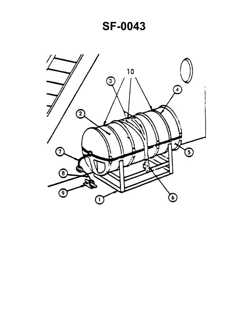
Question: In the illustration shown, the sea painter is identified as item number _____. Illustration SF-0043
A. 3
B. 6
C. 7
D. 9
The Correct Answer is C ### Explanation for Option C (7) The **sea painter** is a heavy line or hawser secured from the forward section of the vessel (the ship) and attached to the forward part (bow) of the small boat, lifeboat, or rigid hull inflatable boat (RHIB). Its primary purpose is to control the boat's position during lowering and recovery, keeping the boat taut and positioned well forward, clear of the ship's side, and away from the propellers. In Illustration SF-0043, item number **7** identifies this specific line running from the ship's deck forward of the davit station to the bow of the boat, which is the definition and typical location of the sea painter. ### Explanation for Incorrect Options * **A) 3:** Item 3 typically identifies components related to the boat's securing mechanisms while stowed, such as the **gripe** (a lashing or wire rope that holds the boat against the chocks) or perhaps a specific steadying line, but not the primary sea painter used during launch/recovery. * **B) 6:** Item 6 usually identifies the **stern painter** (a line similar to the sea painter but attached to the stern of the boat, used for aft control) or the boat falls/hoisting lines, not the forward sea painter. * **D) 9:** Item 9 is generally used to identify a structural component of the davit system, the releasing mechanism, or perhaps the limit switch, but it does not represent the sea painter line.
Question 34
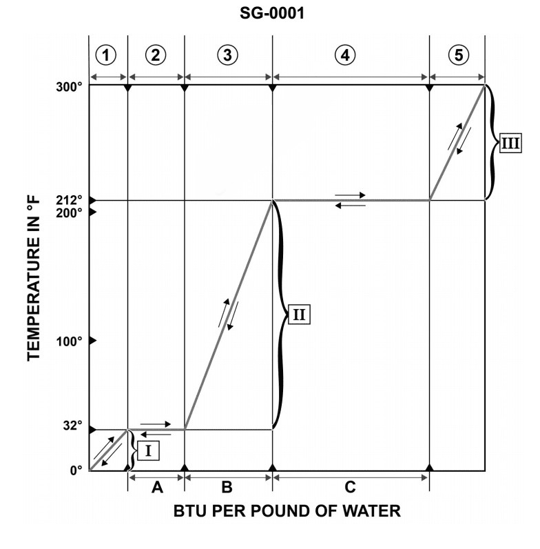
Question: According to the temperature/enthalpy diagram for water at atmospheric pressure, if the substance is undergoing a heat loss, what heat transfer process is represented by the region associated with "4"? Illustration SG-0001
A. Water absorbing its latent heat of vaporization and changing its physical state to become steam.
B. Steam losing its latent heat of condensation and changing its physical state to become water.
C. Steam losing its specific heat and experiencing a drop in temperature.
D. Water absorbing its specific heat and experiencing a rise in temperature.
The Correct Answer is B **Explanation for Option B (Correct):** The standard temperature/enthalpy diagram for water at atmospheric pressure shows five regions. Region 4 is the plateau where the temperature remains constant at 100°C (the boiling/condensation point). This plateau represents a phase change between liquid water and gaseous steam, requiring or releasing the latent heat of vaporization/condensation. Since the substance is undergoing **heat loss** (moving down the enthalpy scale), the process represented by Region 4 is condensation. In condensation, steam (gas) changes its physical state to become water (liquid) by losing its **latent heat of condensation**. **Why the Other Options are Incorrect:** * **A) Water absorbing its latent heat of vaporization and changing its physical state to become steam.** This process is boiling (vaporization) and represents a **heat gain** (enthalpy increase) in Region 4, the reverse of what is described in the question. * **C) Steam losing its specific heat and experiencing a drop in temperature.** This process occurs in Region 5 (superheated steam) and involves the specific heat of steam, not the latent heat associated with a phase change in Region 4. * **D) Water absorbing its specific heat and experiencing a rise in temperature.** This process represents heating liquid water and occurs in Region 3 (the sloping line between 0°C and 100°C). It is a process of **heat gain**, not heat loss.
Question 36
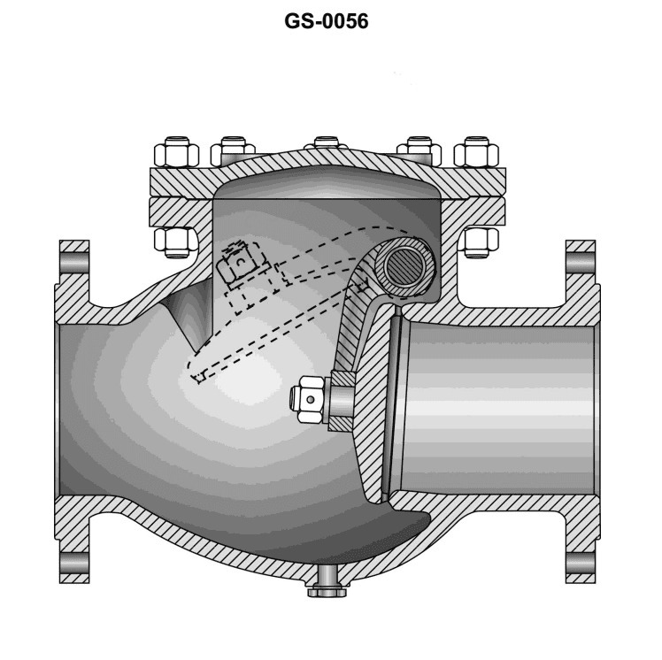
Question: The illustrated valve is known as a __________. Illustration GS-0056
A. swing check valve
B. butterfly lift valve
C. swing globe valve
D. lift gate valve
The Correct Answer is A **Explanation for Option A (swing check valve):** A swing check valve is a type of non-return or one-way valve designed to permit fluid flow in one direction only and automatically prevent backflow. It operates by having a disc or flapper that is hinged (the "swing" mechanism) to the body. When the fluid flows forward, the pressure pushes the disc open. If the flow stops or attempts to reverse, the disc swings shut against the seat, blocking the reverse flow. Illustration GS-0056 typically depicts this specific hinged internal mechanism, characteristic of a swing check valve. **Why the other options are incorrect:** * **B) butterfly lift valve:** This term is a confusing mix of valve types. A standard *butterfly valve* uses a rotating disc (like a butterfly wing) to regulate flow, not a lifting action. A *lift check valve* uses a disc that lifts off the seat, but this is distinct from the hinged mechanism of a swing check valve. The term "butterfly lift valve" does not describe a standard, recognized valve type. * **C) swing globe valve:** A *globe valve* controls and throttles flow by moving a plug or disc perpendicularly towards or away from a seat within a spherical body shape. While a swing valve refers to a type of check valve, combining "swing" and "globe" doesn't accurately describe a recognized standard industrial valve; a globe valve is primarily used for throttling, while a check valve (like a swing check) is only for preventing backflow. * **D) lift gate valve:** A *gate valve* operates by lifting a rectangular wedge or gate completely out of the path of the fluid flow, providing minimal resistance when fully open. A *lift check valve* uses a lifting disc to prevent backflow. The term "lift gate valve" is redundant or incorrect; standard gate valves already lift to operate, and combining this with "lift" does not describe the illustrated check valve structure.
Question 45
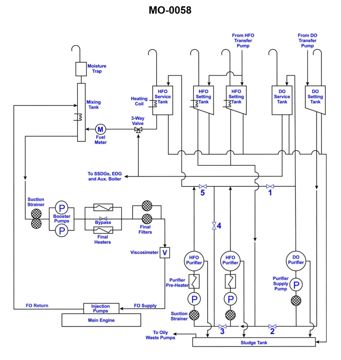
Question: Which of the tanks, shown in the illustration, supplies fuel to the emergency generator? Illustration MO-0058
A. Diesel Oil Service Tank
B. Diesel Oil Settling Tank
C. Diesel Oil Boiler Tank
D. Diesel Oil Booster Tank
The Correct Answer is A. **Explanation for Option A (Diesel Oil Service Tank):** The Diesel Oil Service Tank (or Day Tank) is designed specifically to hold a ready supply of fuel for immediate consumption by engines or generators. In the context of an emergency generator (like those found on a ship or in a critical facility), the service tank ensures that if the main supply is interrupted, or if the fuel needs to be filtered and pre-conditioned immediately before injection, a reliable supply is available directly at the point of use. This tank is positioned to gravity feed or supply the fuel pump of the emergency generator directly. **Why other options are incorrect:** * **B) Diesel Oil Settling Tank:** The Settling Tank's primary function is to receive bulk fuel, allow impurities and water time to separate out due to gravity, and then transfer the cleaned fuel to the Service Tank. It does not directly supply critical equipment like an emergency generator. * **C) Diesel Oil Boiler Tank:** This term is non-standard in typical diesel fuel systems. Diesel oil is the fuel, and it may supply a boiler, but the tank itself is not usually named after the receiving equipment in this manner. It certainly would not be the direct source for an emergency generator. * **D) Diesel Oil Booster Tank:** A booster system typically refers to pumps or equipment used to increase pressure, not a storage tank dedicated to the generator supply. The term does not describe a standard tank function in a fuel oil system.
Question 45
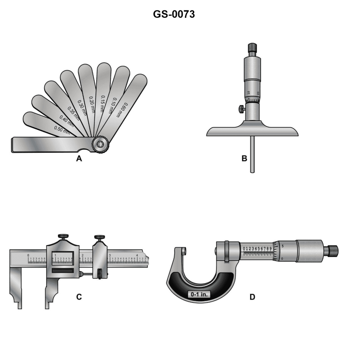
Question: Which of the devices shown in the illustration is designed for both inside and outside measurements? Illustration GS-0073
A. A
B. B
C. C
D. D
The Correct Answer is C **Explanation for Option C (Correct):** Option C points to the **Vernier Caliper** (or often referred to simply as a caliper). Vernier calipers are precision measuring tools universally designed to perform three types of measurements: 1. **Outside diameter/dimensions** (using the main jaws). 2. **Inside diameter/dimensions** (using the upper, smaller jaws). 3. **Depth** (using the extending depth rod/blade). Therefore, a Vernier caliper is designed for both inside and outside measurements. **Explanation for Other Options (Incorrect):** * **A) A:** This device appears to be an **outside micrometer**. Micrometers of this type are specifically designed to measure **outside dimensions** (OD) with high precision but cannot be used for direct inside or depth measurements. * **B) B:** This device appears to be an **inside micrometer** or possibly a bore gauge component. It is specifically designed to measure **inside dimensions** (ID) such as bores or internal grooves, but it cannot be used for outside measurements. * **D) D:** This device appears to be a **dial indicator** mounted on a stand, possibly being used as a comparator or test indicator. While highly useful for checking variations, runout, or comparing dimensions, it is not a direct measuring tool designed to take absolute inside or outside dimensional measurements like a caliper or micrometer.
Question 49
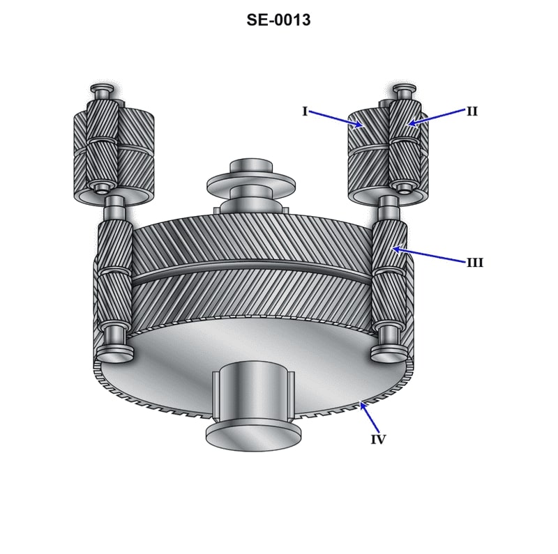
Question: The component shown in the illustration, labeled "I", is the __________. Illustration SE-0013
A. second reduction pinion
B. second reduction gear
C. first reduction gear
D. first reduction pinion
The Correct Answer is C **Explanation for Option C (first reduction gear):** The component labeled "I" in Illustration SE-0013 is typically identified as the **first reduction gear** (or primary driven gear) in a multi-stage gear reduction system, such as those found in starters or transmissions. This gear is larger and meshed directly with the **first reduction pinion** (the smaller driving gear, often attached to the armature shaft or input shaft). Its primary function is to immediately reduce the high rotational speed coming from the input shaft and increase torque, transferring the power to the next stage of the reduction process. **Why the other options are incorrect:** * **A) second reduction pinion:** This would be a smaller driving gear used in the *second* stage of reduction. Component "I" is the larger driven gear in the *first* stage. * **B) second reduction gear:** This would be the larger driven gear in the *second* stage of reduction, which follows the first reduction stage. Component "I" is positioned in the primary stage. * **D) first reduction pinion:** The first reduction pinion is the *smaller* driving gear that meshes with and drives component "I." Therefore, "I" itself cannot be the pinion.
Question 57
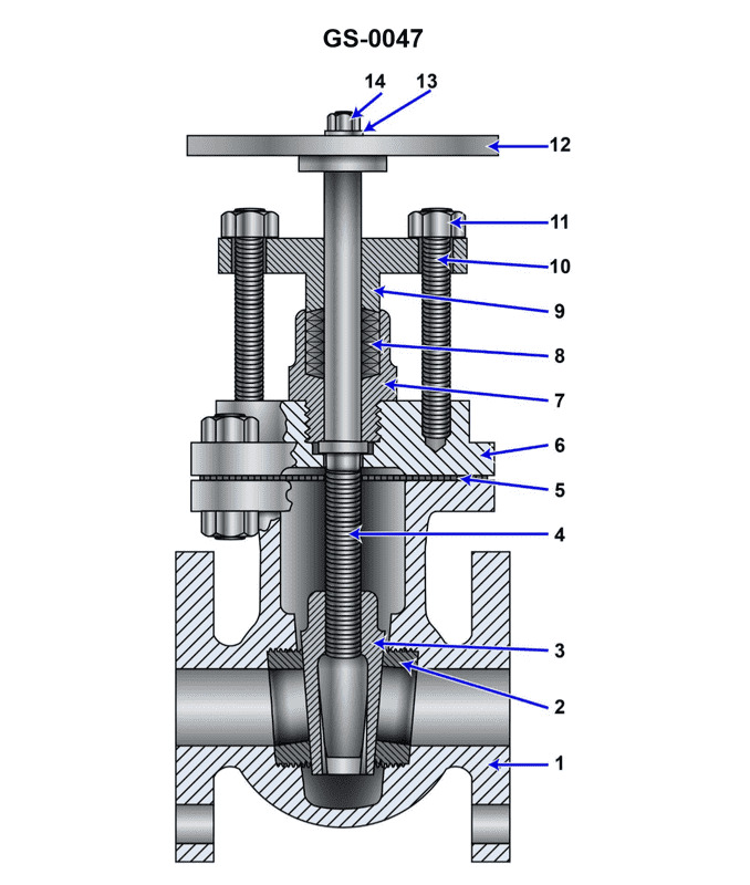
Question: What type of valve is shown in the illustration? Illustration GS-0047
A. Gate valve
B. Globe valve
C. Butterfly valve
D. Check valve
The Correct Answer is A. **Why Option A ("Gate valve") is correct:** The valve depicted in illustration GS-0047 is a **Gate Valve**. A gate valve operates by lifting a rectangular or wedge-shaped gate (the closing mechanism) out of the path of the fluid flow. In the illustration, you can typically identify key characteristics of a gate valve: 1. **Straight-through flow:** The valve body is designed so that when fully open, the flow path is unobstructed, leading to very little pressure drop. 2. **Rising Stem (often):** The handwheel is attached to a threaded stem that rises as the valve is opened, moving the internal gate vertically. 3. **Use for Isolation:** Gate valves are primarily used for starting or stopping flow (isolation service) and are generally operated in the fully open or fully closed position. **Why the other options are incorrect:** * **B) Globe valve:** A globe valve is characterized by a body that has an internal baffle (or partition) where the flow changes direction (often an S or Z pattern). The closing mechanism (disc or plug) moves perpendicularly to the direction of the flow stream when closing against a seat. They are designed for throttling (regulating flow), unlike the gate valve. * **C) Butterfly valve:** A butterfly valve uses a rotating disc (like a butterfly wing) positioned in the center of the pipe. The disc rotates 90 degrees to open or close the flow. They are easily distinguishable by their compact, wafer-style body and simple internal disc mechanism. * **D) Check valve:** A check valve is a one-way valve designed solely to prevent backflow. It operates automatically based on pressure differential; it does not have a handwheel or external actuator for manual control (though some may have an auxiliary manual override).
Question 60
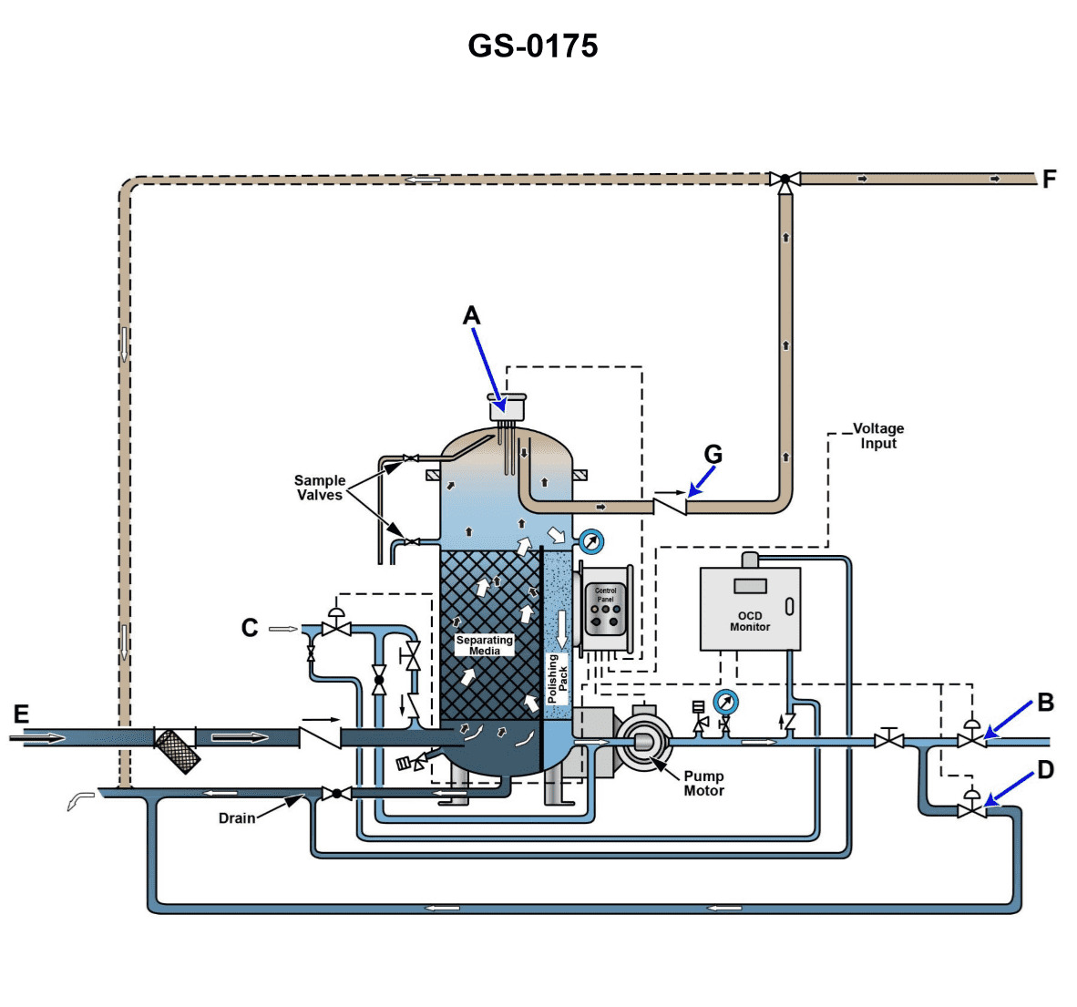
Question: The line labeled "G", as shown in the illustration, would be identified as the _____. Illustration GS-0175
A. clean water flushing line
B. separated oil outlet
C. oily bilge water inlet
D. processed bilge water outlet
The Correct Answer is B. The line labeled "G" in Illustration GS-0175 points to the outlet port specifically designated for the discharge of the separated oil layer that accumulates within the oil content monitor or oil-water separator system. In these systems, once the oily water mixture is processed, the oil (being less dense) separates and collects, needing a dedicated path for removal. Therefore, line G identifies the **separated oil outlet**. * **Option A (clean water flushing line) is incorrect** because a flushing line typically connects to a clean water source (like a potable or service water system) for cleaning the interior of the monitor or sensor, and is usually smaller or located near the sensors, not positioned as the main oil discharge port. * **Option C (oily bilge water inlet) is incorrect** because the inlet line (where the raw, unprocessed bilge water enters the separator/monitor) is usually labeled differently (often positioned lower on the unit) and carries the mixed liquid before separation occurs. * **Option D (processed bilge water outlet) is incorrect** because the processed bilge water outlet (where the cleaned water is discharged overboard or back to the bilge) is typically the largest outlet and is the main exit for the cleaned effluent after the oil has been separated. Line G specifically points to the port for the separated oil itself, not the bulk of the processed water.
Question 61
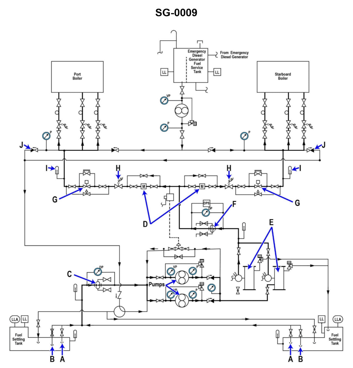
Question: Why are two fuel oil heaters "E" provided in the fuel oil system shown in the illustration? Illustration SG-0009
A. Two heaters are necessary when both boilers steam at full load.
B. To provide a backup in case one of the heaters becomes inoperable.
C. To allow fuel of different temperatures to be provided to each boiler.
D. Each heater supplies fuel to a different boiler.
The Correct Answer is B. Option B ("To provide a backup in case one of the heaters becomes inoperable.") is correct because safety and redundancy are paramount in critical ship systems like the fuel oil supply. If the single operational fuel oil heater fails (due to leakage, fouling, or control system malfunction), the entire propulsion plant could be shut down due to inability to properly atomize the fuel. By providing two heaters, one can remain operational (the standby) while the other is in use, ensuring continuous fuel preparation and allowing maintenance or repair on the faulty unit without interrupting boiler operation. **Why the other options are incorrect:** * **A) Two heaters are necessary when both boilers steam at full load.** This is incorrect. While the required heating capacity must be sufficient for maximum load, modern marine systems typically size **one** operational heater to handle the maximum required flow for all boilers at full load. The second unit serves purely as redundancy/standby, not as an auxiliary unit required simultaneously for capacity. * **C) To allow fuel of different temperatures to be provided to each boiler.** This is incorrect. Both boilers burning the same grade of fuel oil (e.g., Heavy Fuel Oil) typically require the fuel to be heated to the same optimum viscosity/temperature for proper atomization, usually achieved by controlling the temperature in a common line leading to the boilers. * **D) Each heater supplies fuel to a different boiler.** This is incorrect. Fuel oil heaters are generally installed upstream of a common header/ring main. Both heaters are manifolded such that either heater (or a single combination of heaters) can supply the conditioned fuel to the entire system, which then feeds both boilers. They do not operate in a dedicated, isolated fashion for individual boilers.
Question 64
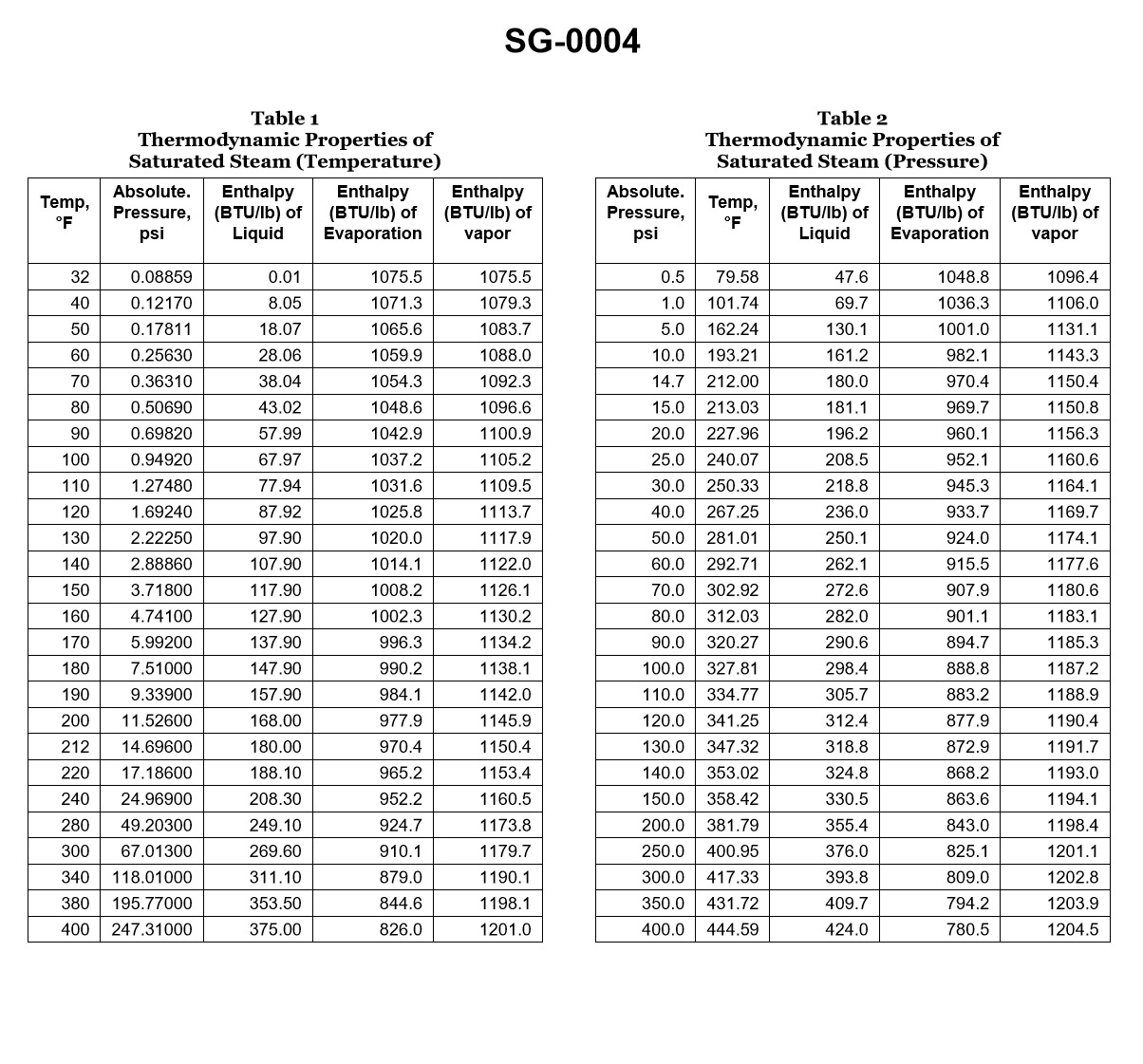
Question: According to the illustrated steam tables, what would be the superheater outlet temperature if saturated steam at 400 psia was elevated 192.83°F? Illustration SG-0004
A. 192.83°F
B. 247.31°F
C. 444.59°F
D. 637.42°F
The Correct Answer is D **Explanation for Option D (637.42°F):** The superheater outlet temperature is calculated by adding the given temperature elevation (the degree of superheat) to the saturation temperature of the steam at the given pressure. 1. **Find the Saturation Temperature ($T_{sat}$):** According to the steam tables (specifically Illustration SG-0004) for steam at 400 psia (absolute pressure), the saturation temperature is $444.59^\circ\text{F}$. 2. **Determine the Temperature Elevation ($\Delta T$):** The steam is elevated by $192.83^\circ\text{F}$. 3. **Calculate the Superheater Outlet Temperature ($T_{out}$):** $$T_{out} = T_{sat} + \Delta T$$ $$T_{out} = 444.59^\circ\text{F} + 192.83^\circ\text{F}$$ $$T_{out} = 637.42^\circ\text{F}$$ Therefore, the superheater outlet temperature is $637.42^\circ\text{F}$. **Explanation of Incorrect Options:** * **A) 192.83°F:** This is the temperature *elevation* (degree of superheat) only. It does not account for the initial saturation temperature of the steam. * **B) 247.31°F:** This value is likely the result of an incorrect calculation, possibly subtracting the temperature elevation from the saturation temperature ($444.59^\circ\text{F} - 192.83^\circ\text{F}$), or using an incorrect saturation temperature (such as 212°F used for standard atmospheric pressure). * **C) 444.59°F:** This is the saturation temperature of the steam at 400 psia. This would be the temperature of the steam *before* it enters the superheater, or if it were still saturated, not the final superheated outlet temperature.
Question 66
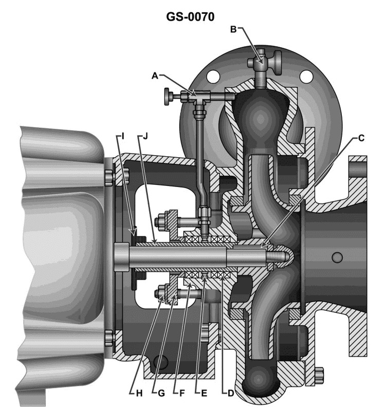
Question: Which of the following statements correctly describes the construction of the close coupled sanitary pump shown in the illustration? Illustration GS-0070
A. The pump suction and discharge connections are made with screwed pipe fittings.
B. The pump housing and motor frame provide for radial adjustment of the shaft coupling.
C. The pump impeller is classified as double suction.
D. The pump and motor have a common shaft.
The Correct Answer is D ### Explanation for Correct Option (D) **D) The pump and motor have a common shaft.** This statement correctly describes the defining characteristic of a **close-coupled pump**. In a close-coupled design (also known as a motor pump), the centrifugal impeller is mounted directly onto the extended shaft of the motor. This eliminates the need for a separate bearing frame, an external flexible coupling, and complex alignment procedures. Because the motor shaft serves as the pump shaft, the pump and motor are considered to share a common shaft. ### Explanation for Incorrect Options **A) The pump suction and discharge connections are made with screwed pipe fittings.** Sanitary pumps are designed for easy cleaning (CIP - Clean In Place) and to prevent the entrapment of bacteria. Standard screwed pipe fittings (NPT) are difficult to sanitize because they create small crevices where media can accumulate. Therefore, sanitary pumps utilize specialized quick-disconnect fittings, such as Tri-Clamp, Bevel Seat, or other sanitary clamp connections, rather than standard screwed fittings. **B) The pump housing and motor frame provide for radial adjustment of the shaft coupling.** Radial adjustment is necessary for external, flexible couplings used in *frame-mounted* pumps to ensure proper alignment between the separately supported motor shaft and pump shaft. Since the close-coupled pump uses a common shaft (D is correct) and eliminates the need for a separate flexible coupling, no radial or angular adjustment between shafts is required or provided for. **C) The pump impeller is classified as double suction.** While double-suction impellers exist (used primarily for very high-flow applications to balance axial thrust), the vast majority of standard close-coupled sanitary pumps use a single-suction (or end-suction) impeller design. Double suction is not a universally defining feature of the typical close-coupled sanitary pump construction.
Question 70
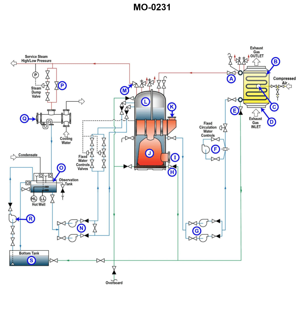
Question: As shown in the illustration, what component would normally be installed at location "I"? Illustration MO-0231
A. Boiler sootblower unit
B. Oil fired mechanical burner
C. Flue gas smoke indicator
D. Boiler water level indicator
The Correct Answer is B **Explanation for B (Oil fired mechanical burner):** The location "I" (as referenced in illustration MO-0231, which typically depicts a marine or industrial watertube boiler setup) is positioned at the front wall (furnace front) of the boiler, directly interfacing with the combustion chamber (furnace). This specific location is where the fuel (in this case, oil) is introduced, atomized, and ignited to create the flame necessary for generating heat. Therefore, an **oil fired mechanical burner** (or register) is the component universally installed at this primary firing location. **Explanation for why other options are incorrect:** * **A) Boiler sootblower unit:** Sootblowers are installed to clean heat transfer surfaces (like superheaters, economizers, or convection tubes) typically located *inside* the gas passages, not directly at the furnace front for firing purposes. * **C) Flue gas smoke indicator:** This instrument is used to monitor the quality of the exhaust gases. It is installed in the stack or uptake (the path where the flue gases exit the boiler), far downstream from the combustion process location "I". * **D) Boiler water level indicator:** This gauge is mounted externally on the boiler drum (steam/water drum) to provide a visual indication of the water level. It is related to the steam generation cycle, not the firing process that occurs at the furnace front (Location "I").