Pass Your Coast Guard Licensing Exams!
Study offline, track your progress, and simulate real exams with the Coast Guard Exams app
QMED02 - Electrician-Refrigerating Engineer
16 images

Question 13
Question: What is the drive arrangement of refrigeration compressor shown in figure "B" of the illustration? Illustration RA-0041
A. open
B. serviceable, bolted, accessible semi-hermetic
C. external drive
D. welded, fully hermetic
The Correct Answer is D. **Explanation for D (welded, fully hermetic) being correct:** Figure B typically illustrates a compressor unit where the motor and the compressor mechanism are enclosed within a single, permanently sealed (welded) steel shell. This design is characteristic of a **welded, fully hermetic** compressor. In this type of arrangement, there are no access panels, bolts, or service valves to open the shell for internal repair; if the internal components fail, the entire unit is replaced. The drive arrangement is internal (hermetic). **Why the other options are incorrect:** * **A) open:** An open drive compressor (or "open type") uses an external motor connected to the compressor shaft via a coupling or belt, requiring a rotating shaft seal to prevent refrigerant leakage. Figure B shows an integrated, sealed unit, not an open-drive system. * **B) serviceable, bolted, accessible semi-hermetic:** A semi-hermetic compressor (or "accessible hermetic") integrates the motor and compressor within a single housing, but the housing is bolted together. This allows technicians to open the unit (serviceable) and replace components like the motor or valve plates in the field. Figure B depicts a welded, non-serviceable housing. * **C) external drive:** "External drive" is synonymous with an "open" compressor (Option A), where the motor is located outside the compressor housing and connects mechanically via a seal. Figure B shows an internal, sealed motor drive.
Question 18
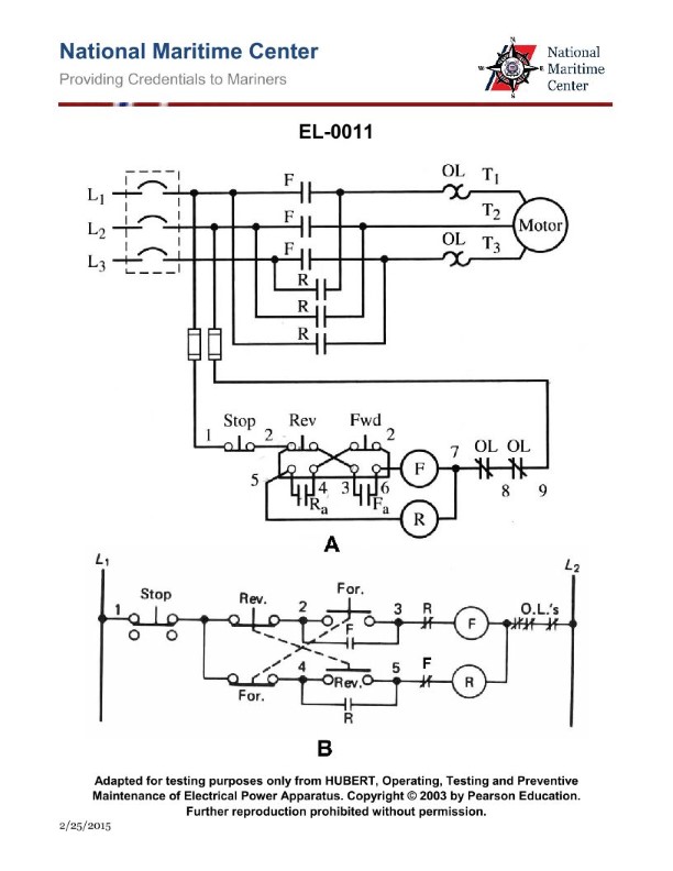
Question: If the supply voltage is 220 volts 60 Hz, what is the operating voltage of the motor controller control circuit illustrated in figure "A" of the illustration? Illustration EL-0011
A. 110 volts DC
B. 110 volts AC
C. 220 volts DC
D. 220 volts AC
The Correct Answer is D **Explanation for Option D (220 volts AC):** The control circuit voltage in an industrial motor control schematic is determined by the voltage supplied to the components (like the contactor coil, overload relay contacts, and pushbuttons) shown in the control section of the diagram. Standard control diagrams, especially for smaller or simpler motor applications where 220V AC is the supply voltage, often use the line voltage (220V AC) directly for the control circuit. Unless the illustration (EL-0011, Figure A) specifically shows a control power transformer (CPT) stepping the voltage down (e.g., to 110V AC or 24V AC) or a rectifier circuit to convert it to DC, it is assumed that the control circuit operates directly off the provided supply voltage. Since the main supply voltage is stated as 220 volts 60 Hz (AC), and assuming the circuit is a common full-voltage non-reversing starter without a CPT, the operating voltage for the control circuit will be **220 volts AC**. **Why the other options are incorrect:** * **A) 110 volts DC:** This is incorrect. The supply is AC (60 Hz), and there is no indication that the voltage is stepped down to 110V *and* converted to DC for the control circuit. 110V DC is an uncommon control standard. * **B) 110 volts AC:** This is incorrect. While 110V AC (or 120V AC) is a very common control voltage, achieving this requires a Control Power Transformer (CPT) to step down the 220V supply. If the illustration (EL-0011, Figure A) does not include a CPT, the control voltage remains 220V AC. * **C) 220 volts DC:** This is incorrect. The supply is 220 volts 60 Hz, which is AC. Operating the control circuit at 220 volts DC would require a rectifier circuit, which is not standard unless specified for high-voltage DC coil operation.
Question 19
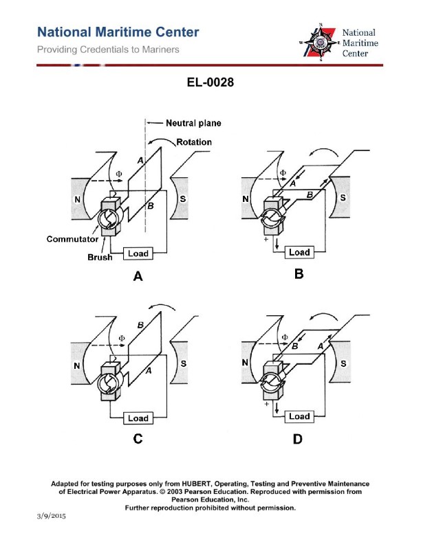
Question: In which figure shown in the illustration will the highest voltage be induced? Illustration EL-0028
A. figure "A" only
B. figure "B" only
C. both figures "A" and "C"
D. both figures "B" and "D"
The Correct Answer is D. ### 2. Explanation of why option D ("both figures "B" and "D"") is correct The voltage (electromotive force, or EMF) induced in a conductor moving through a magnetic field is determined by Faraday’s Law of Induction. This law states that the induced voltage is directly proportional to the rate of change of magnetic flux ($\frac{d\Phi_B}{dt}$). For a conductor moving in a field, the induced voltage ($E$) is maximized when the conductor: 1. Moves at the highest velocity ($v$). 2. Cuts the magnetic field lines perpendicularly (at $90^{\circ}$). 3. Moves through the strongest possible magnetic field ($B$). Figures B and D must represent the conditions under which the rate of flux cutting is maximized—for instance, if B and D show the conductors moving faster than A and C, or if B and D show the conductors moving perfectly perpendicular to the flux lines while A and C show parallel or slow movement. Since the induced voltage depends on the maximum *rate* of cutting the magnetic lines, both figures B and D must illustrate the scenarios yielding the maximum rate, resulting in the highest induced voltage. ### 3. Explanation of why the other options are incorrect **A) figure "A" only is incorrect:** Figure A must represent a scenario where the rate of flux change is low compared to figures B and D. This could be due to slower movement, movement parallel to the magnetic field lines (which induces zero voltage), or movement through a weaker magnetic field. Therefore, A alone does not represent the highest induced voltage. **B) figure "B" only is incorrect:** While figure B is one of the scenarios leading to the highest induced voltage, this option is incomplete because figure D also represents a scenario where the maximum voltage is induced. To provide the complete answer showing all figures with maximum induced voltage, D must also be included. **C) both figures "A" and "C" is incorrect:** As noted above, figures A and C represent scenarios where the induced voltage is low (low rate of flux change). This option incorrectly pairs two low-voltage conditions.
Question 26
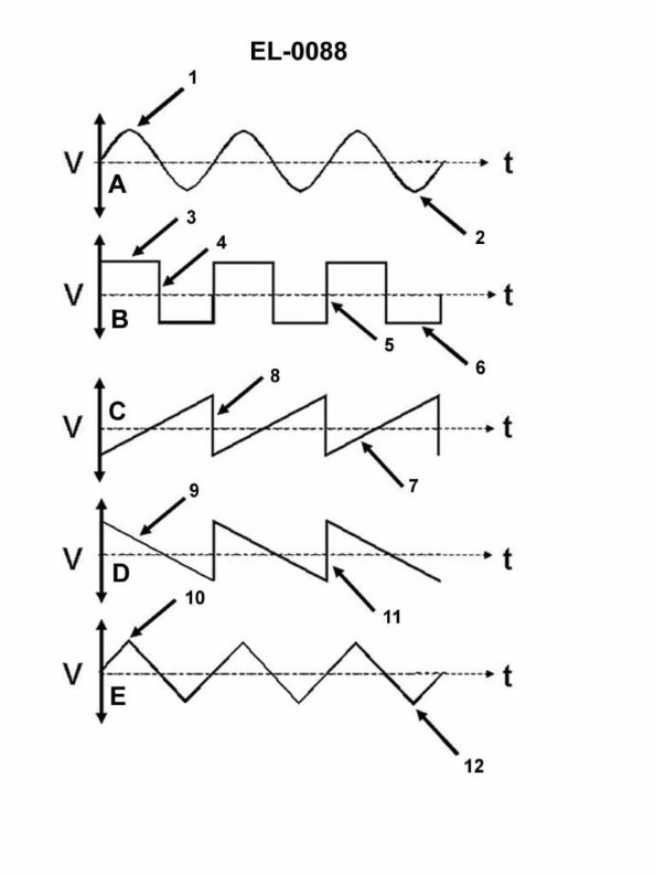
Question: Which line in figure "B" shown in the illustration represents the trailing edge of the wave? Illustration EL-0088
A. 3
B. 4
C. 5
D. 6
The Correct Answer is B **Explanation for Option B (4):** The trailing edge of a wave, in the context of typical wave analysis (like a square wave, pulse, or wavefront in optics/electronics), is the part of the wave that transitions back to its initial state or baseline after reaching its peak or maximum amplitude. In the provided illustration (Figure "B", which typically depicts a square or pulsed wave), Line 4 represents the falling edge—the point where the voltage or amplitude rapidly drops back down to the zero or baseline level. This falling edge is synonymous with the trailing edge of the wave pulse. **Explanation for Incorrect Options:** * **A) 3:** Line 3 represents the **leading edge** (or rising edge) of the wave, where the amplitude rapidly transitions from the baseline to the peak level. * **C) 5:** Line 5 represents the baseline or the minimum amplitude (often zero volts) that exists **after** the pulse has passed. * **D) 6:** Line 6 represents the high-level plateau or the maximum amplitude (the pulse width) between the leading and trailing edges.
Question 30
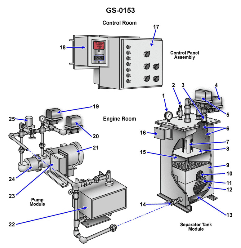
Question: Which of the valves listed for the device shown in the illustration will be open while the unit is operating in the backflush mode? Illustration GS-0153
A. valve "4"
B. valves "4" and "5"
C. valves "4" and "14"
D. valves "4", "5", and "14"
The Correct Answer is C **Explanation for Option C (valves "4" and "14"):** The device shown in illustration GS-0153 is typically a filter unit (often a multimedia or sand filter). "Backflush mode" is a cleaning process where the flow of water is reversed through the filter media to dislodge accumulated debris and flush it out to waste. 1. **Valve "4" (Influent/Inlet Valve):** During normal filtration, water enters the unit through this valve. In backflush mode, water must still enter the unit to perform the cleaning action. Therefore, valve "4" must be **open**. 2. **Valve "14" (Backwash Waste/Drain Valve):** In backflush mode, the dirty water (containing the flushed-out debris) exits the filter unit through the drain or waste line. Valve "14" controls this flow and must therefore be **open** to allow the waste water to leave the system. Thus, for the unit to successfully operate in backflush mode, the influent flow (4) must be open, and the backwash waste flow (14) must be open. **Explanation for Incorrect Options:** * **A) valve "4":** This is insufficient. While valve "4" must be open to let water in, the dirty water has nowhere to exit the system if the drain valve (14) is closed. * **B) valves "4" and "5":** Valve "5" typically controls the effluent/filtered water outlet line (the clean water outlet). During backflush, the clean water outlet must be **closed** to force the incoming water (4) down through the filter and out the waste line (14). Opening valve "5" during backflush would contaminate the clean water line or prevent proper backwashing pressure. * **D) valves "4", "5", and "14":** This is incorrect because valve "5" (the filtered water outlet) must be **closed** during the backflush operation, as explained above.

Question 30
Question: If the valve labeled "D" in the illustration is a suction service valve, what will the port labeled "7" be connected to? Illustration RA-0008
A. to the line connected to the evaporator inlet
B. to the inlet of the compressor
C. to the outlet of the compressor
D. to the line connected to the evaporator outlet
The Correct Answer is D **Explanation for Option D (Correct):** In refrigeration systems, the valve labeled "D" is identified as a **suction service valve**. The suction service valve is mounted on the suction line, which carries low-pressure, low-temperature refrigerant vapor from the evaporator outlet back to the compressor inlet. The main body of the service valve (often port '7' in standard illustrations) is always connected directly to the primary line it serves. Therefore, if "D" is the suction service valve, port "7" will be connected to the main suction line coming **from the evaporator outlet**. **Explanation of Incorrect Options:** * **A) to the line connected to the evaporator inlet:** The line connected to the evaporator inlet is the liquid line, carrying high-pressure liquid refrigerant (or saturated liquid/vapor mix) from the expansion device. The suction service valve is not located on this line. * **B) to the inlet of the compressor:** While the suction line eventually connects to the compressor inlet, the suction **service valve** itself has three ports (front-seat, back-seat, and gauge port). The port '7' (the main line connection) is connected to the suction line that runs between the evaporator and the compressor. If '7' were connected *directly* to the compressor inlet, it would imply the valve is mounted directly on the compressor shell, which is typically the location of a separate service port, not the main flow connection of the valve body itself unless the valve is integrated onto the compressor shell. More accurately, '7' connects to the line coming from the evaporator, feeding the compressor. * **C) to the outlet of the compressor:** The line connected to the outlet of the compressor is the discharge line (or hot gas line), which carries high-pressure, high-temperature vapor to the condenser. The valve serving this location would be the discharge service valve, not the suction service valve.
Question 31
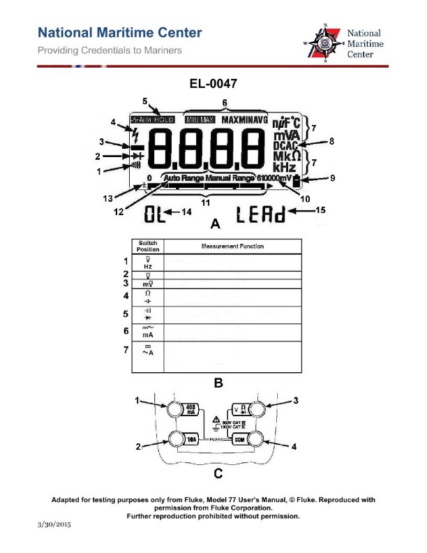
Question: As shown in figures "B" and "C" of the illustration, what should be the switch position and which test lead terminal jacks should be used if your intent is to measure DC currents anticipated as high as 200 milliamps? Illustration EL-0047
A. switch position "7" and terminal jacks "1 and 4"
B. switch position "6" and terminal jacks "2 and 4"
C. switch position "6" and terminal jacks "1 and 4"
D. switch position "7" and terminal jacks "2 and 4"
The Correct Answer is C **Explanation of why Option C ("switch position "6" and terminal jacks "1 and 4"") is correct:** To measure DC current in the milliamps (mA) range, two primary selections must be made on the meter (as defined by illustration EL-0047): 1. **Switch Position:** The selector switch must be set to the DC Milliamps (DC mA) function and range. Position "6" is designated for the DC current (mA) measurement function, and depending on the specific range selected within that position, it handles currents up to a specific limit, which usually includes 200 mA. 2. **Terminal Jacks:** For general voltage, resistance, and standard low/medium current (milliamps) measurements, the test leads must be inserted into the jacks designated for these functions. Jack "4" is the common (COM) terminal, and Jack "1" is the main input terminal for V/$\Omega$/mA. This configuration correctly places the meter in series with the circuit to measure DC current up to 200 mA. **Explanation of why the other options are incorrect:** * **A) switch position "7" and terminal jacks "1 and 4":** While terminal jacks "1 and 4" are correctly used for mA measurements, switch position "7" is typically designated for measuring Resistance ($\Omega$), AC Volts (V~), or a different, non-milliamps range. Therefore, the function/range selector is incorrect. * **B) switch position "6" and terminal jacks "2 and 4":** Switch position "6" correctly selects the DC mA range. However, terminal jack "2" is almost universally designated as the high-current input (e.g., the 10-Amp unfused or fused input). Using jack "2" for a 200 mA measurement is incorrect and would bypass the necessary mA shunt resistor circuitry, often requiring the range switch to be set to a high-Amp setting instead of the mA setting. * **D) switch position "7" and terminal jacks "2 and 4":** Both the switch position "7" (incorrect function) and the terminal jacks "2 and 4" (incorrect leads for mA measurement) are wrong for measuring a 200 mA DC current. This configuration is usually reserved for a high-Amp AC or DC measurement (using Jack 2) or a completely different function (using Position 7).
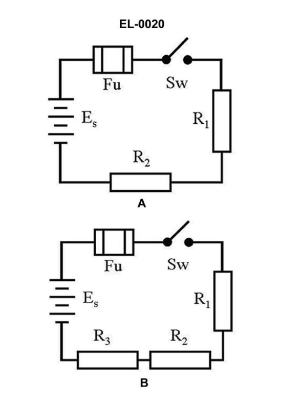
Question 32
Question: What is the power consumed by "R2" in the circuit illustrated in figure "B", if the applied voltage is 24 volts and the resistance of R1 is 3 ohms, R2 is 4 ohms, and R3 is 5 ohms, respectively? Illustration EL-0020
A. 16 watts
B. 20 watts
C. 24 watts
D. 28 watts
The Correct Answer is A ### Explanation of the Correct Answer (A) The power consumed by a resistor ($P$) is calculated using the formula $P = I^2 R$, where $I$ is the current flowing through the resistor and $R$ is the resistance value. Figure B illustrates a series circuit where the total applied voltage ($V_{total}$) is 24 V, and the resistors $R_1$, $R_2$, and $R_3$ are connected end-to-end. **1. Calculate the Total Resistance ($R_{total}$):** In a series circuit, the total resistance is the sum of individual resistances: $R_{total} = R_1 + R_2 + R_3$ $R_{total} = 3 \, \Omega + 4 \, \Omega + 5 \, \Omega = 12 \, \Omega$ **2. Calculate the Total Current ($I_{total}$):** The current is the same throughout a series circuit. Use Ohm's Law ($I = V/R$): $I_{total} = V_{total} / R_{total}$ $I_{total} = 24 \, \text{V} / 12 \, \Omega = 2 \, \text{A}$ Since the circuit is in series, the current flowing through $R_2$ ($I_{R2}$) is the total current: $I_{R2} = 2 \, \text{A}$ **3. Calculate the Power Consumed by $R_2$ ($P_{R2}$):** Use the power formula $P = I^2 R$: $P_{R2} = (I_{R2})^2 \times R_2$ $P_{R2} = (2 \, \text{A})^2 \times 4 \, \Omega$ $P_{R2} = 4 \, \text{A}^2 \times 4 \, \Omega = 16 \, \text{W}$ Therefore, the power consumed by $R_2$ is 16 watts. --- ### Explanation of Incorrect Options **B) 20 watts:** This value does not correspond to the power dissipation of $R_2$. For comparison, the power dissipated by $R_3$ (5 $\Omega$) is $P_{R3} = (2 \text{ A})^2 \times 5 \, \Omega = 20 \, \text{W}$. This option represents the power consumed by R3, not R2. **C) 24 watts:** This value is likely derived from an error such as calculating the power of $R_1$ and $R_2$ combined ($R_1 + R_2 = 7 \, \Omega$) if the current was incorrectly assumed (e.g., $I=2$ A, $P = 4 \times 7 = 28$ W - which is Option D), or perhaps an attempt to calculate the voltage drop across $R_2$ (8V) multiplied by a mistakenly calculated current (3 A, which is incorrect). It does not match the actual power of $R_2$ (16 W). **D) 28 watts:** This value is the power consumed by the first two resistors combined ($P_{R1} + P_{R2}$): $P_{R1} = (2 \, \text{A})^2 \times 3 \, \Omega = 12 \, \text{W}$ $P_{R1} + P_{R2} = 12 \, \text{W} + 16 \, \text{W} = 28 \, \text{W}$. This option represents the combined power of R1 and R2, not the power consumed by R2 alone.
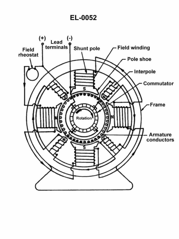
Question 45
Question: As shown in the illustrated DC machine which is configured as a generator, what is the purpose of the interpoles? Illustration EL-0052
A. counteract armature reaction to maintain the brushes in the neutral plane to minimize brush sparking
B. statically balance the stator for uniform weight distribution
C. provide residual magnetism to facilitate an output by means of self-excitation
D. strengthen the main field above and beyond the capability of the main field poles
The Correct Answer is A. **Explanation for Option A (Correct):** The purpose of interpoles (also known as commutating poles) in a DC machine (whether operating as a motor or a generator) is to overcome the distorting effects of armature reaction, specifically in the commutation zone. Armature reaction shifts the magnetic neutral plane (MNP) away from the geometric neutral plane (GNP). During commutation (the process where the current in an armature coil is reversed as it passes under a brush), the coil undergoing reversal is momentarily short-circuited by the brush. If the MNP is shifted, the short-circuited coil will still have a significant induced voltage (reactance voltage), leading to large circulating currents and severe sparking at the brushes. Interpoles are small poles placed midway between the main poles, carrying the armature current, and are wound to produce a flux that directly opposes the armature flux in the commutation zone. By neutralizing the reactance voltage, they ensure commutation occurs essentially without current reversal difficulty (black commutation), thereby keeping the effective neutral plane under the brushes and minimizing brush sparking. **Explanation of Incorrect Options:** * **B) statically balance the stator for uniform weight distribution:** Interpoles are electromagnetic devices designed for magnetic field manipulation and commutation improvement. They have no role in the mechanical or static balancing of the stator or the machine's overall weight distribution. * **C) provide residual magnetism to facilitate an output by means of self-excitation:** Residual magnetism is provided by the main field poles (usually steel) themselves, which retain a small amount of flux after the machine is shut down. This initial residual flux is necessary to start the voltage build-up in a self-excited generator. Interpoles only function when armature current is flowing and do not contribute to the residual magnetism required for starting. * **D) strengthen the main field above and beyond the capability of the main field poles:** Interpoles are designed to create a localized field *opposite* to the armature reaction field in the commutation zone. Their flux is intentionally localized and oriented primarily to aid commutation, not to increase the overall operating strength (magnitude) of the main working flux produced by the main field poles.
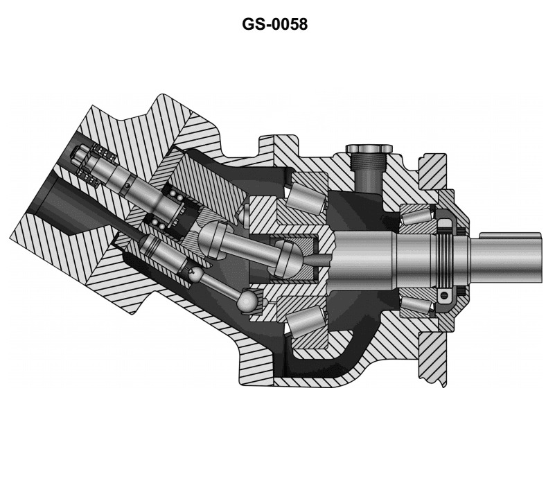
Question 49
Question: The discharge capacity of the axial piston hydraulic pump, shown in the illustration, is _______. Illustration GS-0058
A. variable set by angle determined by operator
B. fixed by the pump housing angle
C. fixed by length of the shaft
D. variable set by adding shorter or longer cylinder block
The Correct Answer is B **Explanation for Option B (Correct Answer):** The illustration (GS-0058, depicting a common type of axial piston pump) shows a **bent-axis type** axial piston pump. In this design, the cylinder block and the drive shaft are connected via a universal joint, and the angle ($\alpha$) between the cylinder block axis and the drive shaft axis is the key determinant of the pump's displacement (discharge capacity per revolution). If this angle ($\alpha$) is mechanically fixed (i.e., the pump is designed with a specific, non-adjustable housing/yoke angle), the volume of fluid displaced per stroke of the piston, and therefore the total discharge capacity per revolution, is **fixed** by this predetermined pump housing angle. **Why other options are incorrect:** * **A) variable set by angle determined by operator:** This would describe a **variable displacement** pump. While bent-axis pumps *can* be designed to be variable (by allowing the angle $\alpha$ to change, often controlled by an actuator or operator input), the question asks about the illustrated pump's capacity in general terms, and standard or basic versions of this design often have a *fixed* housing angle. Assuming a standard, fixed-displacement configuration where the angle is structural, the capacity is fixed, not operator-variable. * **C) fixed by length of the shaft:** The length of the shaft itself does not determine the volumetric displacement. Displacement is determined by the piston area, the number of pistons, and the stroke length, which is a function of the angle ($\alpha$). * **D) variable set by adding shorter or longer cylinder block:** The discharge capacity is based on the internal volume displacement, which relies on the piston stroke (determined by the angle) and the piston bore/area. Swapping cylinder blocks (which would change the overall size and potentially the number of pistons) would change the *design* capacity, but it does not make the capacity *variable* in operation. Furthermore, the length of the cylinder block itself is not the primary factor determining displacement; the bore and stroke are.
Question 51
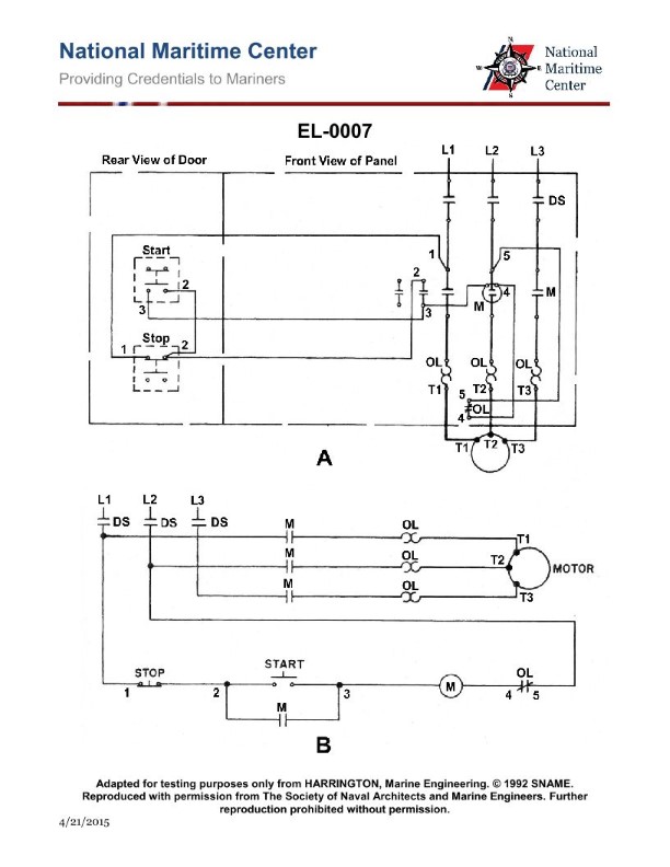
Question: The motor fails to start on an attempted startup. With the start button depressed, a voltmeter reading between 1 and 5, as illustrated in figure "A", indicates line voltage available to the control circuit, what should be your next step in the troubleshooting process? Illustration EL-0007
A. test the contactor coil "M" for continuity and replace if necessary
B. ensure that the disconnect switch (DS) is closed
C. test the stop button for continuity and replace if necessary
D. attempt to reset the overload relay and determine the cause of the overload if applicable
The Correct Answer is D. ### Explanation for D (Correct Option) The scenario describes a motor failing to start when the start button is depressed, but line voltage is confirmed to be available to the control circuit (indicated by a voltmeter reading between points 1 and 5 in Figure A, representing the input and output of the entire control circuit). This means power is getting *to* the control circuit but is not passing through it to energize the motor contactor coil (M). The control circuit typically includes, in series: 1. Power input (1) 2. Fuses/Circuit Protection 3. The Stop Button (normally closed, NC) 4. The Overload (OL) Contacts (normally closed, NC) 5. The Start Button (normally open, NO, bypassed by the M auxiliary contact once started) 6. The Contactor Coil (M) 7. Ground/Neutral (5) If the start button is depressed and the motor does not start, the most common single-point failure preventing power from reaching the coil (M) is an open protective device *downstream* of the main power input, but *upstream* of the coil. The overload (OL) relay contacts (thermal protection) are designed to open and interrupt the control circuit when the motor draws excessive current. Since the failure occurred on startup, the OL relay is the prime suspect for having tripped, interrupting the flow of power to the coil (M). Therefore, the immediate next logical and safest troubleshooting step is to attempt to reset the OL relay. If it resets, the circuit is complete, and the motor should start (or a short-term issue is resolved). If it immediately trips again, a serious fault (like a mechanical jam or short circuit) is confirmed, requiring immediate investigation. ### Why Other Options Are Incorrect **A) test the contactor coil "M" for continuity and replace if necessary** This step is premature. Power must reach the coil before you test the coil itself. If the OL contacts are open, power never reaches the coil, regardless of the coil's health. Testing the OL contacts (or attempting a reset) must logically precede testing the coil. **B) ensure that the disconnect switch (DS) is closed** The voltmeter reading between points 1 and 5 *already confirms* that the disconnect switch (DS) is closed and power is successfully applied to the control circuit inputs. If the DS were open, there would be no line voltage reading. **C) test the stop button for continuity and replace if necessary** The stop button is normally closed (NC). If the stop button had failed (i.e., its contacts were stuck open), power would not reach the rest of the control circuit. However, it is far less common for an NC component like a stop button to fail open than it is for a protective device (the OL relay) to trip. While it's a possibility, the OL relay trip is the standard first assumption when a motor fails to start, making D the better next step.
Question 55
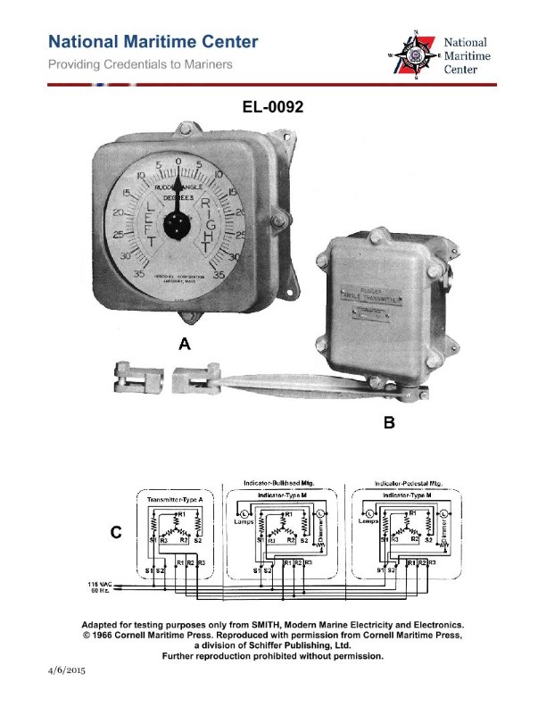
Question: In actual applications, electrical connections associated with "R1, R2 and R3" of the transmitter to "R1, R2, and R3" of the indicators shown in figure "C" of the illustration are made by what means? Illustration EL-0092
A. spliced and taped connections
B. slip rings and brushes
C. soldered contacts
D. solderless crimp-on connectors
The Correct Answer is B. **Explanation of Option B (Slip Rings and Brushes):** The illustration described (figure "C" of illustration EL-0092, which typically depicts a synchro or Autosyn remote indicating system used in aircraft) shows a system where the "transmitter" (often mounted on an engine or flight control surface) needs to send positional data to the "indicator" (in the cockpit). For the system to function, the rotor of the transmitter must be free to rotate continuously or semi-continuously (e.g., following the movement of a throttle, flap, or rudder). The connections designated R1, R2, and R3 are typically the connections to the rotating element (the rotor) of the synchro transmitter, which is excited by AC power (e.g., 26 VAC or 115 VAC). To supply electrical power (R1/R2) or signal reference (R3) to a component that is continuously rotating, **slip rings and brushes** are the required mechanical means. The slip rings are concentric conductive rings mounted on the rotating shaft, and the brushes (usually spring-loaded carbon or metallic contacts) ride on these rings to maintain continuous electrical contact while allowing full rotation. **Why the other options are incorrect:** * **A) Spliced and taped connections:** Splicing and taping are fixed wiring methods. If applied to a rotating component, the wires would twist, break, or short out after very little movement. They are suitable only for static connections. * **C) Soldered contacts:** Soldered contacts create a permanent, rigid electrical connection. Like splicing, they cannot accommodate the continuous rotary motion required between the fixed frame (stator leads) and the moving element (rotor leads) of the transmitter. * **D) Solderless crimp-on connectors:** While modern aviation heavily uses crimp connectors for reliable wiring terminations, these connectors are used to attach wires to fixed terminals. They are a static connection method and cannot facilitate continuous rotational movement between two parts.
Question 62
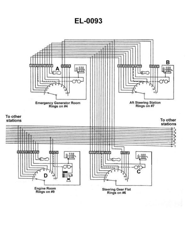
Question: What does the component labeled "B" shown in the illustration represent? Illustration EL-0093
A. selsyn motor
B. bridge rectifier
C. shielded lamp
D. hand-cranked generator
The Correct Answer is D **Explanation for Option D (hand-cranked generator):** The component labeled "B" in electrical schematics, particularly within older or specialized military/communications contexts (like those often featuring illustrations designated by numbers such as EL-0093), often represents a power source that can be operated manually. The symbol for a **hand-cranked generator** (sometimes denoted as G-HND or similar) typically consists of a circle (representing the generator or dynamo) with an arrow or a zig-zag line exiting one side, visually suggesting the mechanical input mechanism (the crank handle). This component is used to generate the necessary AC or DC voltage to power field equipment, such as radio transmitters/receivers, when grid power or batteries are unavailable. **Explanation of Incorrect Options:** **A) selsyn motor:** A selsyn (or synchro) motor is used for remote position sensing or data transmission (e.g., transmitting the angular position of a compass to a remote indicator). Its schematic symbol generally represents a three-phase motor or transformer configuration, which looks significantly different from the basic generator symbol with a manual crank indication. **B) bridge rectifier:** A bridge rectifier is a circuit component (usually four diodes arranged in a specific configuration) used to convert AC voltage into pulsating DC voltage. Its symbol is typically drawn as a diamond shape containing diodes, or simply represented by the standard rectifier symbol, not the rotating machine symbol associated with a generator. **C) shielded lamp:** A shielded lamp (or pilot lamp/indicator light) is typically symbolized by a circle containing a cross (X) or filament representation, sometimes enclosed in a dashed line to indicate shielding. It is an output device (a load) and does not represent a power generation source like a hand-cranked generator.

Question 62
Question: Which of the hand valve configurations for the gauge manifold set is the correct set up for monitoring both the low and high system pressures? Illustration RA-0003
A. A
B. B
C. C
D. D
The Correct Answer is D. **Why option D ("D") is correct:** Option D illustrates the gauge manifold set configured for monitoring both the low and (high) system pressures. To monitor the pressures within the refrigeration or AC system, the gauges must be connected to the system ports, but the valves must be configured to prevent refrigerant flow through the manifold and into the vacuum pump or recovery machine. * The **low-side (blue) hose** is connected to the low-side test port. * The **high-side (red) hose** is connected to the high-side test port. * The **center (yellow) hose** is capped or unconnected to any service equipment. * Crucially, both the **low-side (blue) hand valve** and the **high-side (red) hand valve** are shown in the **closed position (turned fully clockwise)**. When both hand valves are closed, the system pressure flows directly through the hoses and into the respective gauges (low-pressure gauge and high-pressure gauge), allowing the technician to read the system's static pressures without causing cross-contamination, releasing refrigerant, or improperly connecting service equipment. **Why the other options are incorrect:** * **Option A (A) is incorrect:** In this configuration, the high-side (red) valve is shown **open**. Opening the high-side valve while connected to the system and with the center hose capped would potentially allow refrigerant to flow through the manifold if the low-side valve was also open (or could lead to improper operation if service equipment was attached). For simple pressure monitoring, all valves must be closed. * **Option B (B) is incorrect:** In this configuration, the low-side (blue) valve is shown **open**. Opening the low-side valve while connected to the system is unnecessary for simple pressure monitoring and could lead to issues if the center hose was later connected to a vacuum pump or recovery machine, allowing high-pressure refrigerant to flow toward the service equipment or cross-flow through the manifold (depending on the system's differential pressure). For monitoring, both valves must be closed. * **Option C (C) is incorrect:** In this configuration, **both the low-side (blue) and high-side (red) valves are shown open**. This configuration is primarily used for deep vacuum pulling or charging/recovery operations, where refrigerant must flow through the manifold. When simply monitoring pressure, leaving both valves open risks incorrect readings, cross-flow of refrigerant (if system pressures are significantly different), and potential damage to equipment if the center hose is connected to a low-pressure device (like a vacuum pump).
Question 63
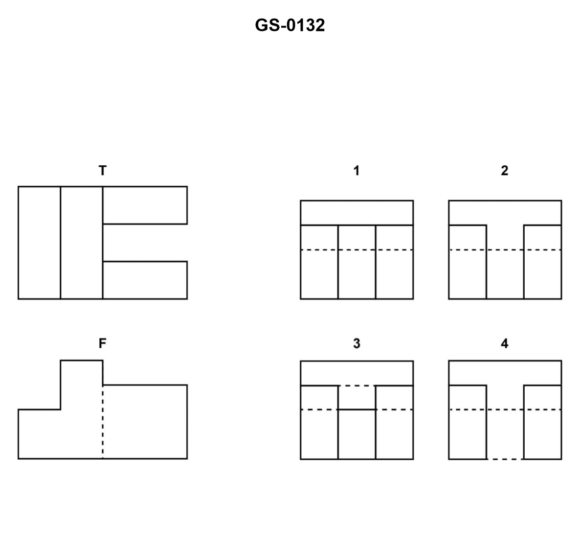
Question: The illustrated drawing shows a correct front "F" and top "T" view of an object. Of the views labeled "1","2","3", and "4", the one that correctly represents the right side view for a third angle projection is_______. Illustration GS-0132
A. 1
B. 2
C. 3
D. 4
The Correct Answer is B ### Explanation for why Option B ("2") is Correct: The problem asks for the correct right side view using a **third angle projection**. In third angle projection, the view is placed in the quadrant adjacent to the face it represents: the top view is placed above the front view, and the right side view is placed to the right of the front view. The front view (F) shows the object has a main rectangular base and an upper, narrower rectangular block centered on the base. To generate the right side view (R), we look at the object from the right side. 1. **Overall Shape:** The object, when viewed from the right, will appear as a rectangle. 2. **Hidden/Visible Features:** The front view (F) and top view (T) both confirm that the upper block is narrower than the base block. Therefore, when looking from the right, the sides of the **upper block** (which are parallel to the viewing direction) are visible. The sides of the **base block** (which extend beyond the upper block) are also visible. Crucially, the **recessed corners** (where the upper block meets the base) are visible edges. 3. **Projection:** The height of the base and the height of the step up to the upper block must align horizontally with the front view (F). The width of the base must align horizontally with the top view (T) and transfer to the right side view (R). View **2** correctly depicts this structure: it shows a large rectangle representing the overall width and height, and an internal horizontal line. This internal horizontal line represents the shoulder or step formed by the narrower upper block resting on the wider base block. Since this step/shoulder is a visible edge when looking from the right (the base is wider than the top block), it is drawn as a **solid line**. ### Explanation for why the other options are incorrect: * **A) 1 is incorrect:** View 1 shows a simple solid rectangle with no internal lines. This would represent a simple rectangular prism, not the stepped object shown in the front and top views. * **C) 3 is incorrect:** View 3 shows a solid rectangle with an internal horizontal **dashed (hidden)** line. A dashed line indicates an edge that is not visible from the viewing direction. The step/shoulder in this object is clearly visible when looking from the right side (because the base block is wider than the upper block), so it must be represented by a solid line. * **D) 4 is incorrect:** View 4 shows a solid rectangle with an internal vertical dashed line. This configuration would represent a hole or slot running through the object from front to back, which is not indicated in the provided top (T) or front (F) views. Furthermore, the object's structure requires a horizontal internal line to depict the height step, not a vertical line.
Question 63
Question: With a service gauge manifold set connected to a refrigerant compressor as shown in the illustration, which arrangement of the gauge manifold set valves and compressor service valves would allow for simultaneous reading of the compressor suction and discharge pressures? Illustration RA-0003
A. Valves "2" and "5" both closed, along with valves "1" and "6" both cracked open off their backseats.
B. Valves "2" and "5" both closed, along with valves "1" and "6" both back-seated.
C. Valves "2" and "5" both open, along with valves "1" and "6" both open in the mid-position.
D. Valves "2" and "5" both open, along with valves "1" and "6" both front-seated.
The Correct Answer is A. ### Explanation of Why Option A is Correct Option A states: "Valves '2' and '5' both closed, along with valves '1' and '6' both cracked open off their backseats." 1. **Purpose of Valves '1' and '6' (Compressor Service Valves):** These are the service valves connecting the compressor to the system and providing access points for the gauge manifold. To read the system pressure (suction and discharge) at the compressor, these valves must be positioned to allow system pressure to reach the gauge port. * **Back-seated:** When a compressor service valve (like '1' or '6') is fully open (back-seated), the gauge port is isolated (closed off). * **Cracked open (off their backseat):** When these valves are turned slightly forward from the fully open (back-seated) position, the service port is opened, allowing system pressure (suction or discharge) to be read on the manifold gauges (G1 and G2). The valve remains primarily open to the system, but now the gauges are connected. 2. **Purpose of Valves '2' and '5' (Manifold Hand Valves):** These are the valves on the gauge manifold itself. * **Closed:** When these valves are closed, they prevent refrigerant from flowing across the manifold (e.g., from high side to low side, or into a center hose connected for charging/evacuation). * **Simultaneous Reading:** To simply read the pressure, the manifold valves ('2' and '5') must be closed to isolate the high-side gauge (G2) from the low-side gauge (G1) and the center hose connection. Therefore, closing the manifold valves ('2' and '5') isolates the gauges from each other and the center port, and cracking open the service valves ('1' and '6') connects the gauges to the suction and discharge lines, allowing for simultaneous pressure readings. *** ### Explanation of Why the Other Options are Incorrect **B) Valves "2" and "5" both closed, along with valves "1" and "6" both back-seated.** * **Incorrect:** While manifold valves '2' and '5' must be closed, back-seating service valves '1' and '6' completely isolates (closes off) the gauge ports, meaning the gauges (G1 and G2) would read zero or ambient pressure, not the system pressure. **C) Valves "2" and "5" both open, along with valves "1" and "6" both open in the mid-position.** * **Incorrect:** Opening manifold valves '2' and '5' connects the high side and low side of the system together, leading to equalization of pressure (a disastrous situation for a running compressor, or resulting in a blended pressure reading). While mid-position on service valves '1' and '6' *does* allow pressure reading, the open manifold valves negate the possibility of reading distinct suction and discharge pressures. **D) Valves "2" and "5" both open, along with valves "1" and "6" both front-seated.** * **Incorrect:** Opening manifold valves '2' and '5' again connects the high and low sides. More critically, front-seating (fully closing) the service valves '1' and '6' completely shuts off the flow of refrigerant from the compressor and system. If the compressor is running, this creates high pressure on the discharge side (potentially triggering a high-pressure cutout) and low pressure on the suction side, but the gauge manifold setup would be incorrect for standard pressure measurement. Furthermore, front-seating the service valves does not typically allow pressure to reach the gauge port; it shuts off the system port entirely.