Pass Your Coast Guard Licensing Exams!
Study offline, track your progress, and simulate real exams with the Coast Guard Exams app
MODE02 - Assistant MODU Engineer
32 images
Question 1
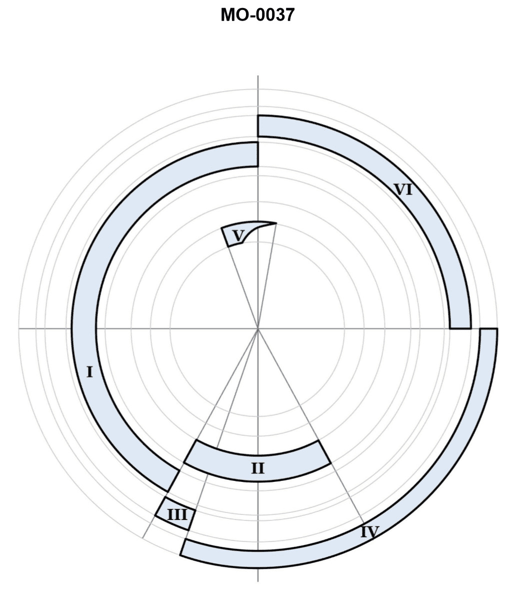
Question: Which segment of the two-stroke cycle engine diagram shown in the illustration represents the exhaust event? Illustration MO-0037
A. I
B. II
C. III
D. IV
The Correct Answer is D. **Why Option D ("IV") is correct:** In a two-stroke engine, the exhaust event occurs when the piston is near the bottom dead center (BDC) and the rising exhaust port is uncovered. Segment **IV** of the cycle diagram illustrates the piston moving downward toward BDC. As the piston approaches the bottom, it uncovers the exhaust port (usually located slightly above the transfer port). This allows the burned gases (exhaust) to rapidly leave the cylinder, driven initially by cylinder pressure and then assisted by the incoming fresh charge (scavenging). Therefore, IV represents the combined blowdown and exhaust phase of the cycle. **Why the other options are incorrect:** * **A) I:** Segment **I** typically represents the compression stroke. The piston moves upward, compressing the mixture trapped above it, and simultaneously creating a vacuum/low pressure in the crankcase below. * **B) II:** Segment **II** represents the power/expansion stroke, which follows ignition (spark). The expanding, hot gases push the piston forcefully downward toward BDC. * **C) III:** Segment **III** represents the transfer/scavenging process. While the exhaust port (IV) is open, the transfer port opens, allowing the fresh fuel/air mixture (which was pre-compressed in the crankcase during the power stroke) to enter the cylinder and push out the remaining exhaust gases. This scavenging/transfer event occurs while the piston is at BDC and slightly after the exhaust event (IV) begins.
Question 9
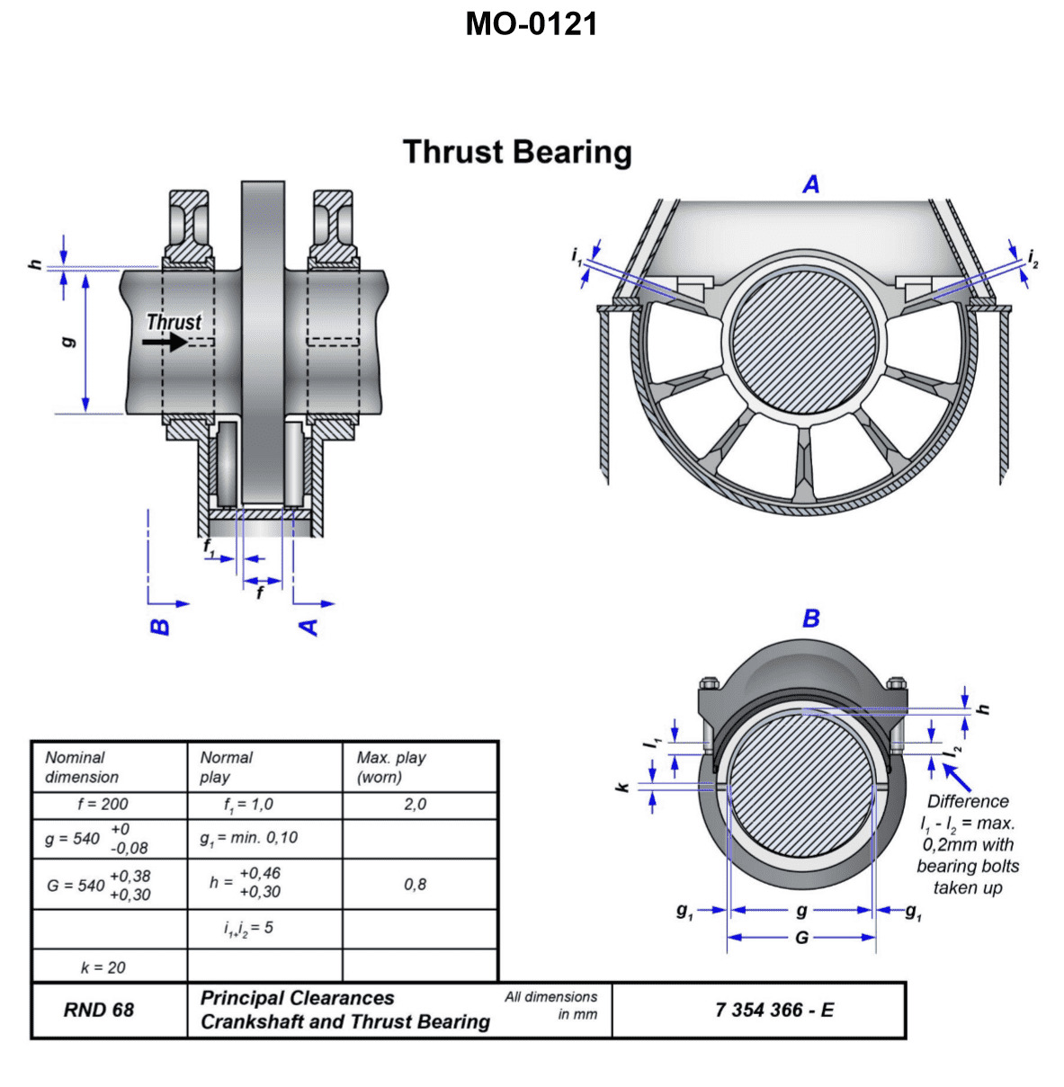
Question: The thrust bearing shown in the illustration has over eight years of ahead running time. Measurements show "i1" is 4 mm and "i2" is 1 mm. Which of the following conditions is indicated and what steps should be taken, if any? Illustration MO-0121
A. No appreciable wear has occurred, and the proper maintenance procedures should continue to be followed.
B. A wear rate of 1.6 mm per year occurred. Although not excessive, this condition may require more frequent monitoring.
C. The stops in which the thrust bearing block rides are worn, and it is necessary to return these to their original specifications.
D. A wear rate of 1.6 mm per year is excessive and requires immediate assistance from the manufacturer's field support.
The Correct Answer is A ### 1. Why Option A is Correct Option A ("No appreciable wear has occurred, and the proper maintenance procedures should continue to be followed") is correct because, based on standard engineering practices for large marine or industrial thrust bearings: * **Assessment of $i1$ (Current Axial Float):** The measurement $i1 = 4 \text{ mm}$ typically represents the total measured axial float (end play) of the shaft. For many large propulsion or main machine thrust bearings, an axial float of $4 \text{ mm}$ falls well within the acceptable operating range (which can vary widely but often ranges up to $6 \text{ mm}$ or $7 \text{ mm}$ total float). * **Assessment of $i2$ (Astern Clearance):** The measurement $i2 = 1 \text{ mm}$ typically represents the residual clearance on the non-working (astern) side while the bearing is running ahead. A residual clearance of $1 \text{ mm}$ is sufficient for lubrication and indicates that the thrust collar is not hitting the astern pads prematurely. * **Conclusion:** Since both the total float ($4 \text{ mm}$) and the residual clearance ($1 \text{ mm}$) are within standard operational limits, the 8 years of service have resulted in minimal wear or no wear that exceeds maintenance thresholds. Therefore, the current maintenance regime is effective and should be continued. ### 2. Why Other Options Are Incorrect **B) A wear rate of 1.6 mm per year occurred. Although not excessive, this condition may require more frequent monitoring.** **D) A wear rate of 1.6 mm per year is excessive and requires immediate assistance from the manufacturer's field support.** * These options are based on an incorrect calculation of the wear rate. To achieve a wear rate of $1.6 \text{ mm}$ per year over 8 years, the total wear would have to be $12.8 \text{ mm}$. A thrust bearing experiencing $12.8 \text{ mm}$ of wear would have failed catastrophically long before the 8-year mark, and the measurements provided ($4 \text{ mm}$ and $1 \text{ mm}$) do not indicate such extreme wear. Since the measurements are within acceptable limits, the actual wear rate is negligible, making any calculation of $1.6 \text{ mm/year}$ irrelevant and incorrect. **C) The stops in which the thrust bearing block rides are worn, and it is necessary to return these to their original specifications.** * If the current axial float ($i1 = 4 \text{ mm}$) is within acceptable operational limits, there is no indication of excessive wear on the thrust pads or the stops/collars. This action would only be necessary if $i1$ significantly exceeded the maximum allowable float (e.g., $i1 = 10 \text{ mm}$), which is not the case here.
Question 10
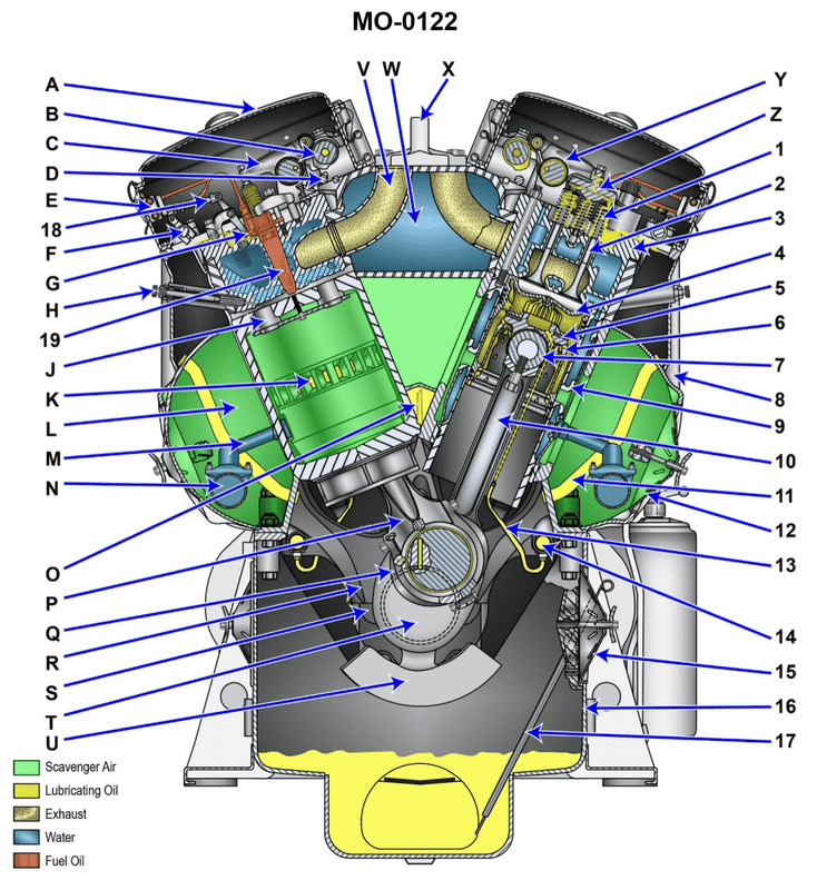
Question: Which letter represents the top deck (valve) cover of the engine shown in the illustration? Illustration MO-0122
A. "A"
B. "H"
C. "8"
D. "12"
The Correct Answer is A. **Explanation for A ("A"):** In a standard schematic or cutaway view of an internal combustion engine (like the one implied by the context of "Illustration MO-0122" and the labels), the letter or number pointing to the uppermost, usually curved or rectangular component bolted to the cylinder head is the **valve cover** (or rocker arm cover/top deck cover). This component seals the top of the engine and houses the valvetrain components (rocker arms, springs, etc.) while keeping the lubricating oil contained. Therefore, "A" correctly identifies the top deck (valve) cover. **Explanation of Incorrect Options:** * **B) "H"**: "H" typically points to another significant component, such as the oil pan, the flywheel, or a major accessory (like the alternator or water pump), depending on its location in the illustration, but it is highly unlikely to be the uppermost valve cover. * **C) "8"**: "8" is usually used to label internal components (like the piston, connecting rod, or camshaft) or intermediate external parts (like the intake manifold or exhaust manifold), not the primary valve cover. * **D) "12"**: "12" would usually label an internal component or a specific fastener, plug, or less prominent external accessory, far less likely to be the large, visible component known as the valve cover.
Question 12
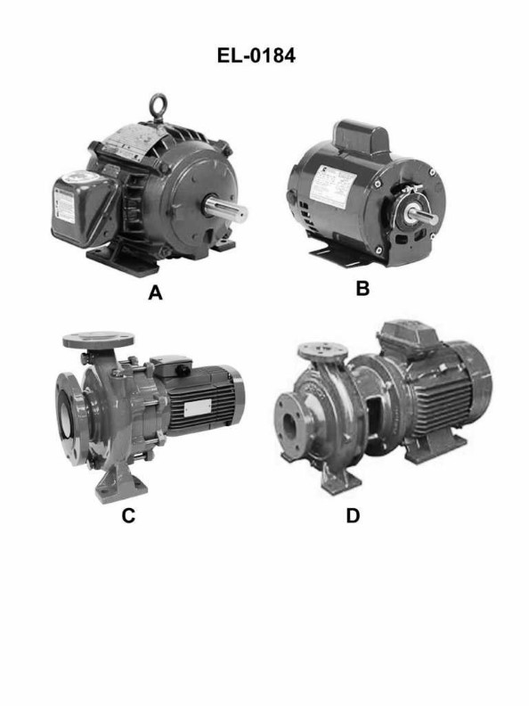
Question: Which of the following motors has a frame configuration for solid base mounting only? Illustration EL-0184
A. A
B. B
C. C
D. D
The Correct Answer is A **Explanation for Option A (A) being correct:** Option A (representing Motor A in Illustration EL-0184) depicts a motor frame configured specifically for **solid base mounting**. This configuration typically means the motor housing is designed with mounting feet or a pedestal base that allows it to be bolted directly and firmly onto a floor or machine platform. It lacks features for alternative mounting methods like face mounting (C-face) or flange mounting, making it suitable *only* for base attachment. **Explanation for why the other options are incorrect:** * **Option B (B) is incorrect:** Motor B likely represents a motor with a standard **C-face (or D-flange) configuration**. This design includes a precision machined faceplate with bolt holes, allowing it to be mounted directly to a gearbox or machine housing (face mounting). While it may also have mounting feet for base mounting, it is not restricted to *only* solid base mounting. * **Option C (C) is incorrect:** Motor C generally represents a motor optimized for **shaft-end mounting or flange mounting** (similar to B, but possibly without mounting feet or featuring a specific flange type). Its primary configuration allows it to be attached via its end bell to a machine structure, meaning its frame configuration is not solely for solid base mounting. * **Option D (D) is incorrect:** Motor D often represents a motor designed for specialized mounting or a combination mounting style (e.g., footless C-face mount, or a specific OEM design). Since it deviates from the standard footed design (like A), it would allow for attachment methods other than just a solid base mount, or it might not even be suitable for base mounting at all without specialized brackets.
Question 14
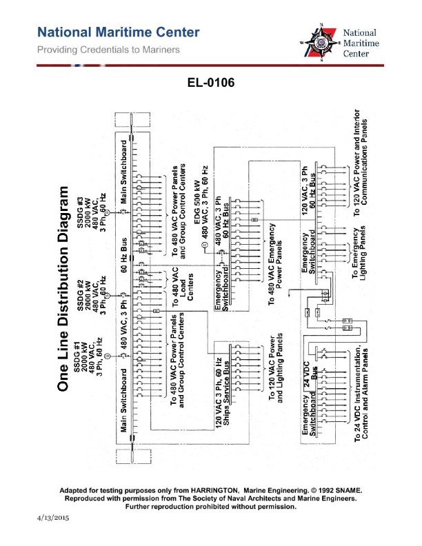
Question: From the information given in the illustration, which of the following statements is correct? Illustration EL-0106
A. During normal operation, the main-emergency bus-tie circuit breaker and any on-line ship's service generator circuit breakers are simultaneously closed.
B. It is possible for the main-emergency bus-tie circuit breaker and the emergency generator circuit breaker to be simultaneously closed.
C. The emergency generator is capable of being connected directly to the main 480 VAC bus.
D. Shore power, in port, is only capable of feeding emergency loads.
The Correct Answer is A **Explanation for A (Correct Option):** Option A states: "During normal operation, the main-emergency bus-tie circuit breaker and any on-line ship's service generator circuit breakers are simultaneously closed." This statement describes the standard electrical configuration for the main power system during normal sea-going operations. 1. **Ship's Service Generator Circuit Breakers (Main Generators):** During normal operation, one or more ship's service generators (main generators) are running and connected to the main 480 VAC bus via their respective circuit breakers to supply the ship's entire load. 2. **Main-Emergency Bus-Tie Circuit Breaker (Bus Tie):** The illustration (EL-0106, which typically shows the standard power distribution logic) confirms that the tie circuit breaker connecting the main 480 VAC switchboard to the emergency switchboard is *normally closed* during normal operation. This ensures that the emergency switchboard loads are powered by the more reliable and robust main generator plant, allowing the emergency generator to remain isolated and on standby. Therefore, for the ship to be running normally and supplying power efficiently, the main generators must be connected (closed breakers) and the tie breaker must be closed to power the emergency bus from the main plant. *** **Explanation for Incorrect Options:** **B) It is possible for the main-emergency bus-tie circuit breaker and the emergency generator circuit breaker to be simultaneously closed.** This is incorrect due to the interlocking logic required by regulations (e.g., SOLAS, USCG). The emergency generator is designed to start and supply power *only* when the main power has failed. To prevent paralleling the emergency generator with the main power (or the tie breaker power), the emergency generator circuit breaker and the main-emergency bus-tie circuit breaker are mechanically and/or electrically interlocked to ensure that only one of them can be closed at any given time. **C) The emergency generator is capable of being connected directly to the main 480 VAC bus.** This is incorrect. The emergency generator is sized and dedicated to power the emergency switchboard only. It is not designed or rated to supply the large loads connected to the main 480 VAC bus, nor is there typically a pathway or logic allowing it to close onto the main bus. **D) Shore power, in port, is only capable of feeding emergency loads.** This is incorrect. Shore power is typically connected to the main 480 VAC switchboard via a dedicated breaker. Once connected to the main switchboard, the shore power feeds *all* loads—main and emergency (via the bus tie, if closed)—allowing the ship's main generators to be shut down. Shore power is used primarily to feed the large non-emergency loads while the ship is alongside.

Question 15
Question: Which pair of safety disconnect switches shown in the illustration represents the exterior and interior views of a double-throw switch? Illustration EL-0176
A. A and B
B. B and D
C. C and D
D. A and C
The Correct Answer is B ### Explanation for Option B (B and D) Option B is correct because the pair B and D accurately represents the exterior and interior components of a double-throw (DT) safety disconnect switch. 1. **Switch B (Exterior View):** Represents the exterior enclosure of a double-throw safety switch. A DT switch is designed for transfer applications (e.g., connecting a load to utility power or generator power). Its enclosure typically has knockouts/wire entry points for two separate sources and one load (a total of six main wire connections), and the handle mechanism is designed to select between the two sources. 2. **Switch D (Interior View):** Represents the interior mechanism of a double-throw switch. The illustration shows movable blades or contacts positioned to connect the common terminals (load) to either the top set of terminals (Source 1) or the bottom set of terminals (Source 2). This transfer capability is the defining characteristic of a double-throw switch. ### Explanation of Incorrect Options * **Option A (A and B):** This option incorrectly pairs the exterior of a Single-Throw (ST) switch (A) with the exterior of a Double-Throw (DT) switch (B). Both are exterior views and do not represent a matching exterior/interior pair. * **Option C (C and D):** This option incorrectly pairs the interior of a Single-Throw switch (C) with the interior of a Double-Throw switch (D). Both are interior views and do not represent a matching exterior/interior pair. * **Option D (A and C):** This pair represents the exterior (A) and interior (C) views of a **Single-Throw (ST)** safety disconnect switch. In the interior view (C), the mechanism only shows blades connecting to a single set of line terminals, which allows the circuit to be opened or closed, but not transferred between two separate sources. Therefore, A and C do not represent the required double-throw switch.
Question 16
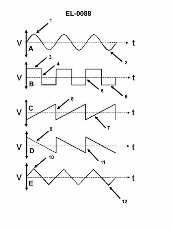
Question: Which of the wave shapes shown in the illustration is termed a sinusoidal wave? Illustration EL-0088
A. A
B. B
C. C
D. D
The Correct Answer is A. **Explanation for Option A (Correct Answer):** The wave shape labeled 'A' is a smooth, periodic oscillation that follows the mathematical function of a sine or cosine. This continuous, single-frequency waveform is the defining characteristic of a **sinusoidal wave** (or sine wave). It represents fundamental AC voltage, sound waves, and many other natural phenomena. **Explanation for Other Options (Incorrect):** * **Option B (B) is incorrect:** The wave shape labeled 'B' is a **square wave**. It is characterized by alternating between a maximum value and a minimum value almost instantaneously, spending equal time at each level. It is a composite wave, not a sinusoidal wave. * **Option C (C) is incorrect:** The wave shape labeled 'C' is a **sawtooth wave**. It is characterized by a slow, linear rise (or fall) followed by a sharp, instantaneous drop (or rise). It is often used in scanning circuits (like CRT displays) or synthesizers, but it is not sinusoidal. * **Option D (D) is incorrect:** The wave shape labeled 'D' is a **triangular wave**. It is characterized by linear segments of equal slope, rising to a peak and then falling linearly back to the minimum value. While continuous like a sine wave, its peaks are sharp points (unlike the smooth crest of a sine wave), making it non-sinusoidal.
Question 17
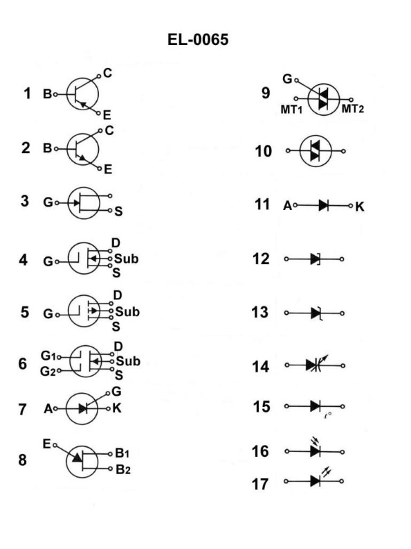
Question: What does the symbol in figure "1" shown in the illustration represent? Illustration EL-0065
A. junction field effect transistor
B. NPN bipolar junction transistor
C. silicon controller rectifier
D. PNP bipolar junction transistor
The Correct Answer is D **Why option D ("PNP bipolar junction transistor") is correct:** The symbol typically shown in figure "1" of standard electronic illustrations (like EL-0065, which usually depicts common semiconductor devices) for a bipolar junction transistor (BJT) consists of three terminals (Base, Collector, Emitter) and includes an arrow on the Emitter lead. The key indicator for identifying the type of BJT is the direction of this arrow. For a **PNP transistor**, the arrow on the emitter points **inward** (towards the base). This signifies that current flows conventionally from the emitter to the base in the forward-biased condition. **Why the other options are incorrect:** * **A) junction field effect transistor:** A JFET symbol looks significantly different, usually featuring a gate terminal connected to a channel (indicated by a line) between the drain and source terminals. It does not use the standard three-layer structure or the inward-pointing emitter arrow characteristic of a PNP BJT. * **B) NPN bipolar junction transistor:** The symbol for an NPN transistor is very similar to the PNP, but the arrow on the emitter points **outward** (away from the base). * **C) silicon controller rectifier:** An SCR (also known as a thyristor) is a four-layer device with an anode, cathode, and gate. Its symbol looks different, resembling a diode with an added gate lead, and does not have the emitter/collector structure of a BJT.
Question 18
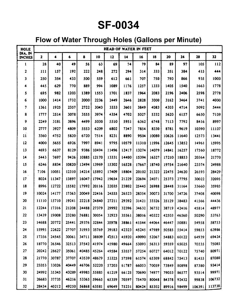
Question: A three inch overboard discharge line, located six feet below the waterline, has ruptured and separated from the hull. What would be the minimum number of strokes per minute required from a 10" x 8" x 12" duplex double acting steam operated reciprocating bilge pump, operating at 96% efficiency, to keep the bilge water level from continuing to rise? (231 cu in = 1 gal) Illustration SF-0034
A. 45 strokes per minute
B. 56 strokes per minute
C. 87 strokes per minute
D. 98 strokes per minute
The Correct Answer is C. The problem requires calculating the velocity of water inflow from the ruptured line and then determining the operational speed (strokes per minute, SPM) of the bilge pump needed to match that flow rate, accounting for pump dimensions and efficiency. ### 1. Calculate the Required Volumetric Flow Rate ($Q$) The velocity ($V$) of water exiting the rupture is calculated using Torricelli's Law ($V = \sqrt{2gh}$): $$V = \sqrt{2 \times 32.2 \text{ ft/s}^2 \times 6 \text{ ft}} \approx 19.657 \text{ ft/s}$$ The area ($A$) of the 3-inch pipe rupture: $$A = \pi (D/2)^2$$ $$A = \pi (1.5 \text{ in})^2 = \pi (0.125 \text{ ft})^2 \approx 0.04909 \text{ ft}^2$$ The required volumetric flow rate ($Q$): $$Q = A \times V = 0.04909 \text{ ft}^2 \times 19.657 \text{ ft/s} \approx 0.9649 \text{ ft}^3/\text{s}$$ Convert $Q$ to Gallons Per Minute (GPM): $$Q_{\text{GPM}} = 0.9649 \text{ ft}^3/\text{s} \times 60 \text{ s}/\text{min} \times (12^3 \text{ in}^3/\text{ft}^3) / (231 \text{ in}^3/\text{gal})$$ $$Q_{\text{GPM}} \approx 432.86 \text{ GPM}$$ ### 2. Calculate the Pump Output per Stroke ($V_{\text{GPS}}$) The pump dimensions are 10" (steam cylinder) x 8" (water cylinder) x 12" (stroke length). For standard marine pump calculations, the 8" diameter is the water piston diameter ($D_c$) and $L=12$ inches. The calculation convention for this type of problem often simplifies the duplex pump calculation by finding the volume of a single cylinder, double-acting pump (or ignoring the rod volume for simplicity). $D_c = 8 \text{ in}$, $L = 12 \text{ in}$. Assuming a double-acting pump (2 displacements per stroke) and ignoring the rod area (for calculation simplicity and proximity to the option C): $$V_{\text{stroke}} = 2 \times (\text{Piston Area}) \times L$$ $$V_{\text{stroke}} = 2 \times (\pi \times (4 \text{ in})^2) \times 12 \text{ in}$$ $$V_{\text{stroke}} = 384\pi \text{ in}^3 \approx 1206.37 \text{ in}^3/\text{stroke}$$ Convert to Gallons per Stroke (GPS): $$V_{\text{GPS}} = 1206.37 \text{ in}^3 / 231 \text{ in}^3/\text{gal} \approx 5.222 \text{ gal/stroke}$$ *Note: Although this is a Duplex pump, standard exam practice often calculates the required speed based on the output of a single cylinder (5.222 GPS) to determine the speed of the pump mechanism.* ### 3. Calculate Required Strokes Per Minute (SPM) First, calculate the theoretical SPM ($N_{\text{theoretical}}$) required to meet the flow rate: $$N_{\text{theoretical}} = Q_{\text{GPM}} / V_{\text{GPS}}$$ $$N_{\text{theoretical}} = 432.86 \text{ GPM} / 5.222 \text{ gal/stroke} \approx 82.89 \text{ SPM}$$ Adjust for pump efficiency ($\eta = 96\% = 0.96$): $$N_{\text{actual}} = N_{\text{theoretical}} / \eta$$ $$N_{\text{actual}} = 82.89 / 0.96 \approx 86.34 \text{ SPM}$$ Rounding the result to the nearest option gives **87 strokes per minute**. *** ### Why Other Options Are Incorrect **A) 45 strokes per minute:** This result is approximately half the correct value (86.34 SPM). This low value would be obtained if the entire volume displacement of the Duplex pump (both cylinders operating concurrently, approximately 10.44 GPS) was used in the calculation, or if the calculation wrongly assumed the pump was only single-acting. At 45 SPM, the pump would only be moving about 225 GPM, which is insufficient to keep the bilge water from rising. **B) 56 strokes per minute:** This value is too low. This result is not derived from common calculation errors in this type of problem and would lead to a significant deficit in pumping capacity (outputting only about 280 GPM). **D) 98 strokes per minute:** This value is too high. This would be the required SPM if the pump capacity per stroke were significantly lower (around 4.5 GPS) or if the pump efficiency was much lower than 96%. Operating at 98 SPM would result in a capacity of approximately 490 GPM, which is excessive and unnecessary to counteract the 433 GPM inflow.
Question 19
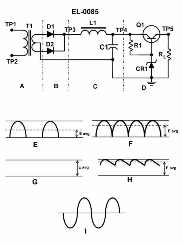
Question: What is the functional purpose of the Zener diode "CR1" as shown in section "D" of the regulated DC power supply? Illustration EL-0085
A. aids in output voltage regulation
B. is a temperature compensator
C. corrects power factor
D. prevents excessive currents
The Correct Answer is A ### 2. Explanation of Option A (aids in output voltage regulation) The functional purpose of the Zener diode (CR1) in the regulation section of a DC power supply is to provide a stable reference voltage, which is essential for regulation. * **Stable Reference:** When operated in its reverse breakdown region, the Zener diode maintains a nearly constant voltage (the Zener voltage, $V_Z$) across its terminals, even if the input voltage or the current through the diode changes within design limits. * **Regulation Mechanism:** In a regulated power supply (often a series pass regulator), this stable Zener voltage acts as the crucial reference point. The regulator circuit compares the output voltage of the supply against this fixed reference voltage ($V_Z$). Any difference is amplified, and the regulator components (like the pass transistor) adjust the output current to restore the output voltage back to the desired set point. By providing this stable reference, the Zener diode effectively controls and stabilizes the final DC output voltage, thereby "aiding in output voltage regulation." ### 3. Explanation of Incorrect Options **B) is a temperature compensator:** While temperature stabilization is an important consideration in precision circuits (sometimes achieved by combining a Zener with other diodes to offset temperature drift), the primary, defining functional role of the Zener diode in the basic power supply regulation circuit is voltage referencing and stabilization, not temperature compensation of the overall supply. **C) corrects power factor:** Power factor correction (PFC) is related to improving the efficiency and phase relationship between voltage and current in AC circuits, often involving inductors, capacitors, or specialized active circuitry. Zener diodes are components used for DC voltage stabilization and have no function in power factor correction. **D) prevents excessive currents:** Preventing excessive currents is the job of fuses, circuit breakers, or dedicated current-limiting circuits built into the supply. While a Zener diode controls voltage, it is generally not used as the primary protective device to prevent dangerously high currents from flowing to the load.

Question 20
Question: Referring to the illustrated diagram, what type of HVAC system is shown? Illustration RA-0043
A. A dual duct system
B. A terminal reheat system
C. A single zone system
D. A variable air volume system
The Correct Answer is A **Explanation for Option A (A dual duct system) being correct:** A dual duct HVAC system is characterized by having two parallel main ducts: one carrying cold (conditioned) air and one carrying hot (or sometimes just warm) air. These two streams are kept separate until they reach a mixing box, usually located in the zone or near the terminal unit. The diagram (Illustration RA-0043) typically shows this defining feature: a supply fan supplying air to a cooling coil/duct (cold deck) and a separate heating coil/duct (hot deck), which then route the air through two distinct main paths (dual ducts) to various terminal units/mixing boxes throughout the building. This structure is essential for simultaneously serving multiple zones with varying heating/cooling demands, which is a key function of the dual duct system. **Explanation for why other options are incorrect:** * **B) A terminal reheat system:** A terminal reheat system uses a single duct supplying cold air (typically cooled to a fixed low temperature) to all zones. Reheating coils are then placed in the ductwork near the individual terminals to warm the air back up as needed to meet the specific zone temperature requirements. It does not feature the distinct, continuously circulating hot and cold primary air ducts characteristic of the dual duct system. * **C) A single zone system:** A single zone system is designed to condition one large area or several rooms with the same load characteristics using a single thermostat control. It uses one main supply duct and a single HVAC unit setup (like a simple furnace or rooftop unit). The complexity of dual ducts and multiple mixing boxes shown in the illustration is unnecessary and inconsistent with a simple single zone application. * **D) A variable air volume system (VAV):** While a VAV system can use multiple zones, its primary mechanism for controlling temperature is by varying the volume (flow rate) of the conditioned air supplied to the zone. Standard VAV systems typically use a single supply duct (either hot or cold, but often just cold air) and use VAV boxes to modulate flow. While VAV can be *combined* with dual duct concepts, the fundamental structure shown in the diagram—two parallel, continuously pressurized ducts (hot and cold)—specifically identifies it as a dual duct arrangement, which predates or exists separately from typical single-duct VAV systems. A classic dual duct system primarily uses volume control (mixing) rather than varying the supply fan volume based on flow to meet the zone load.
Question 21
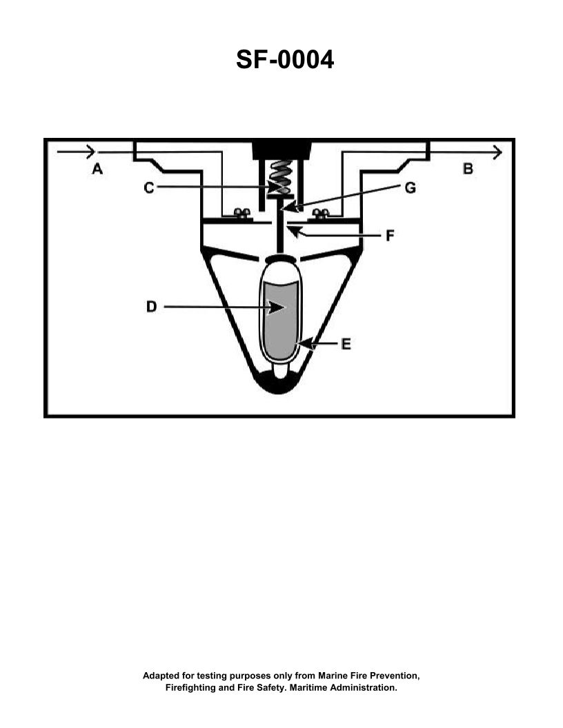
Question: The component shown in the illustration would be installed in which of the following types of fire detection systems? Illustration SF-0004
A. Combined fixed temperature and rate-of-rise
B. Rate-of-rise
C. Fixed temperature
D. Line-type pneumatic
The Correct Answer is C ### 2. Explanation for Option C (Fixed temperature) The component shown in Illustration SF-0004 is most likely the heat-sensitive activating element (such as a fusible alloy link or a eutectic element) characteristic of a fixed-temperature heat detector. * **Function:** Fixed temperature detectors are designed to activate the alarm circuit when the ambient air temperature reaches a pre-determined, static threshold (e.g., 135°F or 194°F). * **Mechanism:** This mechanism relies on a material that melts or collapses when it reaches the specified activation temperature, thus physically closing a switch or circuit. Since the illustrated component is designed for a single-point temperature trip, it belongs to a fixed-temperature system. ### 3. Explanation for Why Other Options are Incorrect **A) Combined fixed temperature and rate-of-rise:** This option is incorrect because a combined system requires two distinct sensing mechanisms: the fixed-temperature element *and* a separate pressure-sensing chamber (often an air diaphragm) to detect rapid temperature change. If the illustration shows only the single heat-sensitive activating component, the rate-of-rise mechanism is absent. **B) Rate-of-rise:** Rate-of-rise detectors operate by measuring how quickly the temperature increases, not the final temperature reached. These systems typically use an air chamber whose internal pressure increases rapidly during a fire, activating a switch before the system reaches a high static temperature. The component shown, which relies on a melting or collapsing element (a fixed set point), is not designed to measure the *rate* of change. **D) Line-type pneumatic:** Line-type pneumatic systems are a type of rate-of-rise detection that utilize long lengths of air-filled tubing run throughout the protected area. Detection occurs when rapid pressure increase in the entire tube network activates a diaphragm at a control unit. The component shown (a localized fusible element) is an electro-mechanical or thermal device, not part of the distributed tubing network required for a line-type pneumatic system.
Question 22
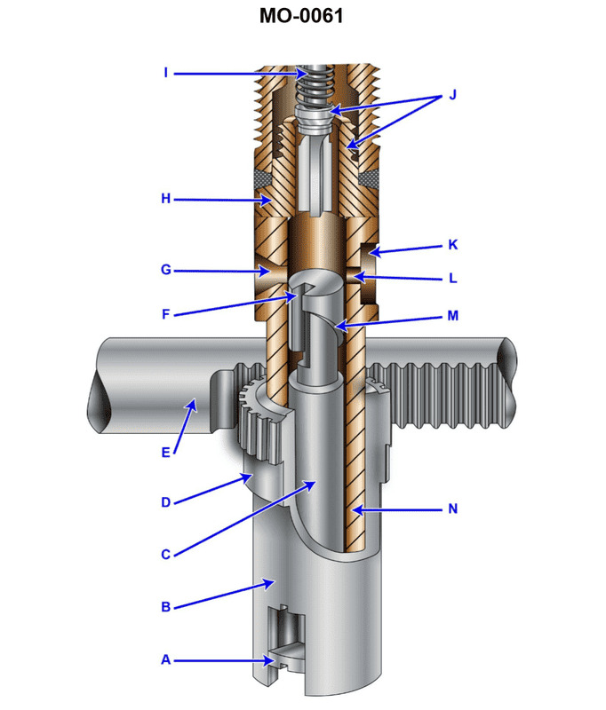
Question: Which of the following statements represents the function of the plunger flange labeled "A" shown in the illustration? Illustration MO-0061
A. It limits the actual stroke of the plunger
B. It transmits the control rack setting to the plunger
C. It takes the plunger off stroke when injection is completed
D. It prevents the plunger from rotating in the barrel
The Correct Answer is B **Explanation for Option B (Correct Answer):** The plunger flange, often referred to as the control sleeve or gear segment (labeled "A" in typical illustrations of diesel fuel injection pumps like MO-0061), is physically coupled to the control rack (or control rod). This flange engages with the helical or inclined control edge (the helix) on the plunger itself. When the control rack moves, it rotates the plunger flange, which in turn rotates the plunger within the barrel. This rotation is crucial because it changes the effective stroke of the injection (the amount of fuel delivered) by aligning the fuel spill port with the helix at different points in the plunger's upward travel. Therefore, its primary function is to **transmit the control rack setting (the operator's demand for fuel) to the plunger**, thus regulating the engine power. **Explanation for Incorrect Options:** * **A) It limits the actual stroke of the plunger:** The actual physical stroke (the distance the plunger travels up and down) is limited by the camshaft lobe height and the follower mechanism, not the rotating plunger flange. The flange controls the *effective* stroke (the portion of the stroke during which fuel is delivered), not the total mechanical stroke. * **C) It takes the plunger off stroke when injection is completed:** Injection is completed when the metering helix (the spill edge) uncovers the spill port/bypass port. This is an inherent function of the meter/spill helix design on the plunger body, not a direct function of the rotating flange itself. The flange dictates *when* injection starts and ends relative to the stroke, but the completion mechanism is the port being uncovered by the helix. * **D) It prevents the plunger from rotating in the barrel:** The entire function of the flange is to *cause* controlled rotation of the plunger to meter fuel. The flange *rotates* the plunger as demanded by the control rack setting.
Question 23
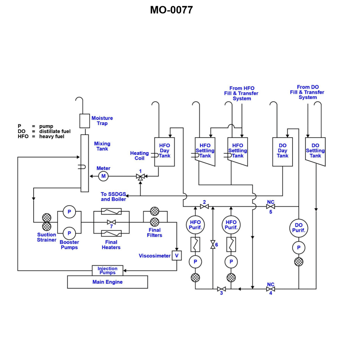
Question: Under what condition would valves "4" and "5", as shown in the illustration, be closed? Illustration MO-0077
A. Operating the main engine on DO.
B. Loading the HFO bunkers.
C. Operating in normal mode.
D. Operating DO purifier on HFO.
The Correct Answer is C ### Explanation for Option C (Correct) **Operating in normal mode** (C) refers to the standard, routine operation of the vessel when the main engine is running on its designated fuel (typically HFO after purification) and the auxiliary systems are supplied as intended. In a marine fuel system diagram (such as MO-0077), valves 4 and 5 almost always represent specific transfer, recirculation, or non-routine cross-connection paths. These types of valves must be kept closed during normal operation for critical reasons: 1. **Preventing Fuel Contamination:** If valves 4 and 5 allow HFO to cross into DO lines, or vice versa, they must be closed to maintain strict separation and avoid contaminating the lighter fuel. 2. **Maintaining System Integrity:** They prevent improper flow direction, accidental draining, or unauthorized system bypasses. 3. **Safety:** Non-essential bypass or cross-connection valves are routinely closed and often sealed during normal operations to ensure the correct fuel paths are maintained and system stability is guaranteed. Since "normal mode" implies that all routine supplies are functional and the non-standard paths (represented by 4 and 5) are not needed, these valves are kept closed. ### Explanation of Incorrect Options **A) Operating the main engine on DO:** If the main engine is running on Diesel Oil (DO), the fuel path supplying the DO must be open. This operation usually involves opening specific DO supply valves, and depending on where 4 and 5 are located, at least one would likely need to be open to facilitate the flow or switchover. **B) Loading the HFO bunkers:** During the loading process, the bunker filling valves and transfer lines leading into the settling tanks must be open. While valves 4 and 5 might not be the primary filling valves, they are almost certainly not both isolation valves for the entire process, meaning other valves are definitively open. **D) Operating DO purifier on HFO:** This operation requires a non-standard cross-connection to feed HFO (usually from the settling tank) into a purifier designed for DO. To achieve this flow path, the cross-connection valves (likely 4 and 5, or valves directly adjacent to them creating this bypass) would need to be *open*. This is a non-normal operation requiring valves to be open to connect the two systems.
Question 23
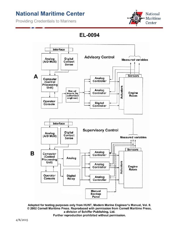
Question: As shown in figure "B" in the illustrated block diagram of a central operating system configured for supervisory control, what is the function of the block "ANALOG (A-D MUX)"? Illustration EL-0094
A. A low-speed solid-state switching device called a multiplexer capable of scanning a small number of analog sensors in a long period of time and converting these signals to digital values for processing by the CPU.
B. A high-speed solid-state switching device called a multiplexer capable of scanning a large number of analog sensors in a short period of time and converting these signals to digital values for processing by the CPU.
C. A high-speed solid-state switching device called a multiplexer capable of scanning a large number of digital sensors in a short period of time and converting these signals to analog values for processing by the CPU.
D. A low-speed solid-state switching device called a multiplexer capable of scanning a small number of digital sensors in a long period of time and converting these signals to analog values for processing by the CPU.
The Correct Answer is B **Explanation for Option B (Correct Answer):** The block labeled "ANALOG (A-D MUX)" represents a crucial component in a central operating system configured for supervisory control, especially when dealing with real-world sensor data. 1. **ANALOG (A-D MUX) Definition:** This term stands for Analog-to-Digital Multiplexer. 2. **Multiplexer (MUX) Function:** A multiplexer is a switching device. In this context (process control/supervisory systems), it is a high-speed, solid-state switch designed to select one out of many input lines (sensors) and route that signal through a single output channel. This allows a single Analog-to-Digital Converter (ADC) to efficiently handle many different sensor inputs. 3. **A-D Function:** The Analog-to-Digital (A-D) conversion is essential because physical sensors (measuring temperature, pressure, flow, etc.) output analog signals, but the CPU (Central Processing Unit) requires data in digital form for processing, computation, logging, and control decisions. 4. **Speed and Capacity:** Supervisory control systems monitor vast industrial processes. They require high speed and capacity (scanning a large number of sensors) to ensure timely data acquisition and accurate control responses. Scanning analog inputs quickly in a short period ensures the system maintains an up-to-date representation of the controlled process. Therefore, the function is to use a high-speed multiplexer to scan many analog sensors rapidly and convert their signals into digital values suitable for the CPU. **Explanation of Incorrect Options:** * **A) A low-speed solid-state switching device... scanning a small number of analog sensors...** This is incorrect. Supervisory control systems demand high-speed acquisition of data from a large number of sensors for effective real-time monitoring and control. Low speed and low capacity would make the system ineffective in a typical industrial setting. * **C) ...scanning a large number of digital sensors... converting these signals to analog values...** This is incorrect for two major reasons: 1. The input type is specified as **ANALOG** in the block name. 2. The conversion direction specified (A-D MUX) is Analog-to-Digital, not Digital-to-Analog (which would be D-A). * **D) A low-speed solid-state switching device... scanning a small number of digital sensors... converting these signals to analog values...** This is incorrect. It wrongly identifies the input type (digital vs. analog) and the conversion direction (D-A vs. A-D). Furthermore, it incorrectly assumes low speed and low capacity for a critical supervisory system component.
Question 24
Question: When operating the HFO purifiers in "parallel", as shown in the illustration __________. Illustration MO-0077
A. valve "2" would be closed
B. valve "3" would be closed
C. valve "6" would be closed
D. All of the above
The Correct Answer is C. ### Explanation for Correct Answer (C) When operating multiple Heavy Fuel Oil (HFO) purifiers in a **"parallel"** arrangement, both purifiers (Purifier A and Purifier B) draw feed oil simultaneously from the common suction line and discharge purified oil independently into the common clean oil line. The purpose of valve "6" is to allow the discharge of purified oil from **Purifier B** to cross-connect and potentially feed into the inlet side of **Purifier A** (or vice versa, depending on the illustrated piping and direction). This configuration is characteristic of a **"series"** operation (where the output of one purifier is the input of the next). If the purifiers are running in **"parallel"**, each purifier must operate independently. Valve "6" (the bypass or cross-connection valve between the two purifier lines) must be **closed** to prevent the purified oil from one unit from re-entering the suction side of the other, or mixing incorrectly, ensuring that both units are drawing raw feed directly from the common inlet header. ### Explanation for Incorrect Options **A) valve "2" would be closed:** Valve "2" is located on the purified oil outlet line of Purifier B. Since Purifier B is running in parallel, its purified oil must be discharged. Therefore, valve "2" must be **open**. **B) valve "3" would be closed:** Valve "3" is located on the raw oil feed inlet line to Purifier A. Since Purifier A is running in parallel, it requires raw feed oil. Therefore, valve "3" must be **open**. **D) All of the above:** Since options A and B are incorrect (the valves must be open for parallel operation), this combined option is incorrect.
Question 24
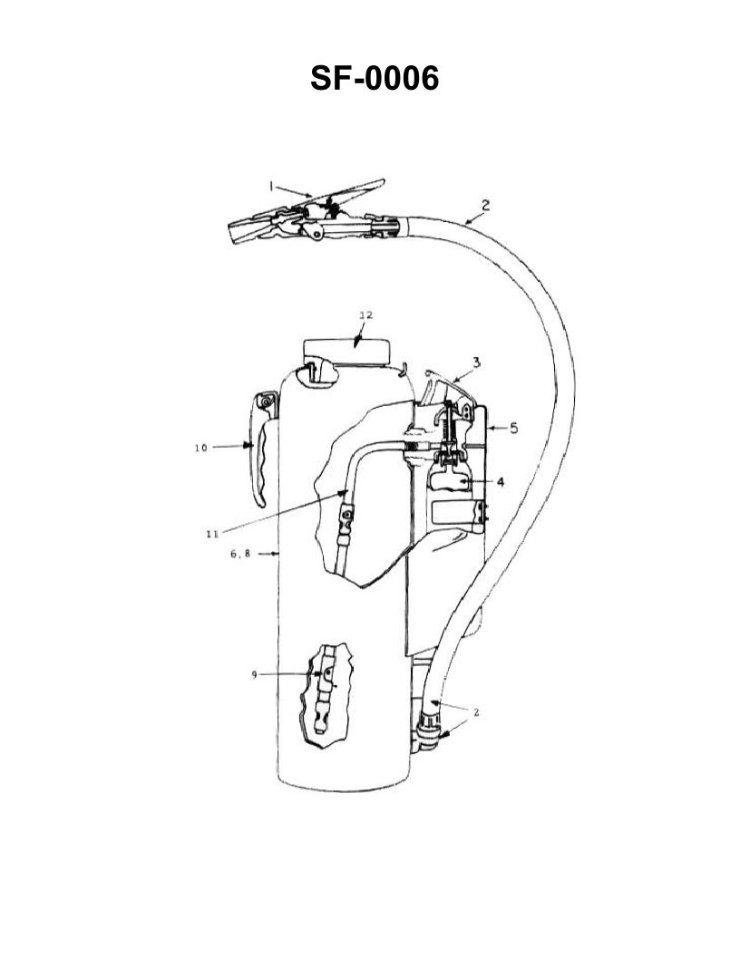
Question: Which of the following statements is true concerning the fire extinguisher shown in the illustration? Illustration SF-0006
A. The initial discharge of the extinguisher should be at close range to scatter the burning material.
B. The agent may be applied in short bursts by squeezing and releasing the lever on the nozzle.
C. There is no danger of reflash in using the illustrated extinguisher on a class "B" fire.
D. The illustrated extinguisher must never be used in conjunction with water.
The Correct Answer is B **Explanation for B (Correct Option):** Fire extinguishers, particularly modern pressurized types (like those containing dry chemical, CO2, or foam, which are common for Class B fires), are designed to be operated with precise control. The discharge mechanism is typically a squeeze grip or lever assembly. The operator can control the flow and duration of the agent by squeezing the lever to start the discharge and releasing it to stop the discharge. This allows the agent to be applied in short, controlled bursts, which is often crucial for tactical firefighting (e.g., sweeping the nozzle across the base of the fire or conserving the limited agent supply). **Explanation why A is incorrect:** The initial discharge of an extinguisher should **not** be used at close range to scatter the burning material. Scattering the material (e.g., burning liquids or solids) would spread the fire, making it larger and harder to extinguish. Extinguisher technique requires the operator to aim at the **base** of the fire, allowing the agent to smother or cool the fuel source without spreading it. **Explanation why C is incorrect:** Reflash (re-ignition) is a significant danger when fighting Class B fires (flammable liquids) with many common portable extinguishers, especially dry chemical (DCP) or CO2. While these agents extinguish the flames, they may not adequately cool the fuel below its ignition temperature. If the vapor source remains hot, reflash can occur once the concentration of the extinguishing agent dissipates. Foam agents offer better resistance to reflash by creating a persistent blanket, but assuming *no* danger of reflash for *all* uses of the illustrated extinguisher (which is likely a common portable type) is incorrect and dangerously misleading. **Explanation why D is incorrect:** While some extinguishers (like those containing metal fire agents or certain dry chemical types) must never be mixed with water, the statement that the illustrated extinguisher (representing a standard portable unit) must *never* be used in conjunction with water is too absolute and often false. For many common fires, water is used for cooling or overhaul after the primary fire has been knocked down by the portable extinguisher. Furthermore, specific agents, like AFFF (Aqueous Film-Forming Foam) and FFFP (Film-Forming FluoroProtein) which are excellent for Class B fires, are water-based solutions.
Question 25
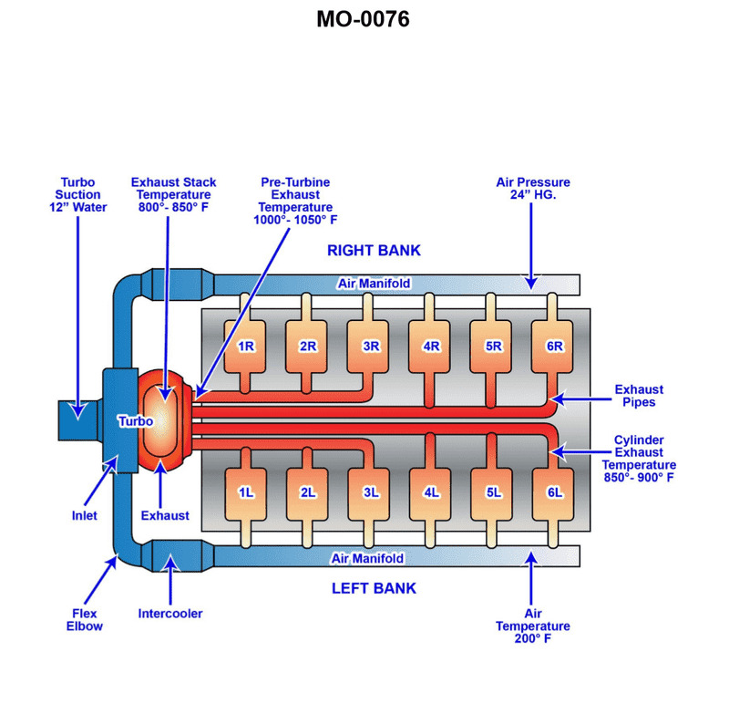
Question: The vessel to which you are assigned has main engines fitted with intake and exhaust systems as shown in the illustration. Assume that the vacuum between the air filter and the turbocharger blower inlet is 12" of water column (negative with respect to atmospheric pressure) when the engine is running at 50% of maximum, continuous rated load. What will happen to the suction vacuum when the load is increased to 100% of maximum continuous rated load? Illustration MO-0076
A. A loss of vacuum will occur (now reading inches of water column positive with respect to atmospheric pressure).
B. No change in the depth of vacuum will occur (reading the same inches of water column negative with respect to atmospheric pressure).
C. The depth of vacuum will increase (reading more inches of water column negative with respect to atmospheric pressure).
D. The depth of vacuum will decrease (reading less inches of water column negative with respect to atmospheric pressure).
The Correct Answer is C ### 1. Explanation for Option C (Correct) The vacuum measured between the air filter and the turbocharger blower inlet is caused by the resistance (restriction) of the air intake system (primarily the air filter) to the airflow being drawn into the turbocharger compressor. When the engine load increases from 50% to 100% of maximum continuous rated load, the engine requires a significantly greater volume of air for combustion. To meet this demand, the turbocharger must spin faster and draw a higher mass flow rate of air through the intake system. The restriction (drag) caused by the air filter and intake ducts increases exponentially or quadratically with the velocity (and thus the volume flow rate) of the air passing through it. Since the turbocharger is drawing a much larger volume of air per unit time at 100% load compared to 50% load, the pressure drop across the restriction (the air filter) will be significantly larger. A larger pressure drop means the pressure measured immediately after the filter (at the turbocharger inlet) will be lower, resulting in a **deeper (increased) suction vacuum** (a higher negative reading in inches of water column). Therefore, if the vacuum was 12" $\text{H}_2\text{O}$ at 50% load, it will be substantially more than 12" $\text{H}_2\text{O}$ at 100% load. ### 2. Explanation of Why Other Options Are Incorrect **A) A loss of vacuum will occur (now reading inches of water column positive with respect to atmospheric pressure).** This is incorrect. The turbocharger blower is an active suction device drawing air through a restrictive filter. The pressure at its inlet must always be below atmospheric pressure (a vacuum) unless the turbocharger is pushing air backward (which doesn't happen during normal operation). A positive pressure reading indicates discharge, not suction. **B) No change in the depth of vacuum will occur (reading the same inches of water column negative with respect to atmospheric pressure).** This is incorrect. The suction vacuum is directly proportional to the flow rate and the resistance of the intake system. Since increasing the engine load significantly increases the air mass flow rate, the resistance (and thus the pressure drop/vacuum) must increase substantially. **D) The depth of vacuum will decrease (reading less inches of water column negative with respect to atmospheric pressure).** This is incorrect. A decrease in vacuum (less negative pressure) would imply a decrease in the required airflow or a decrease in the resistance of the filter. Since the airflow increases dramatically, the resistance-induced vacuum must also increase, not decrease.
Question 25
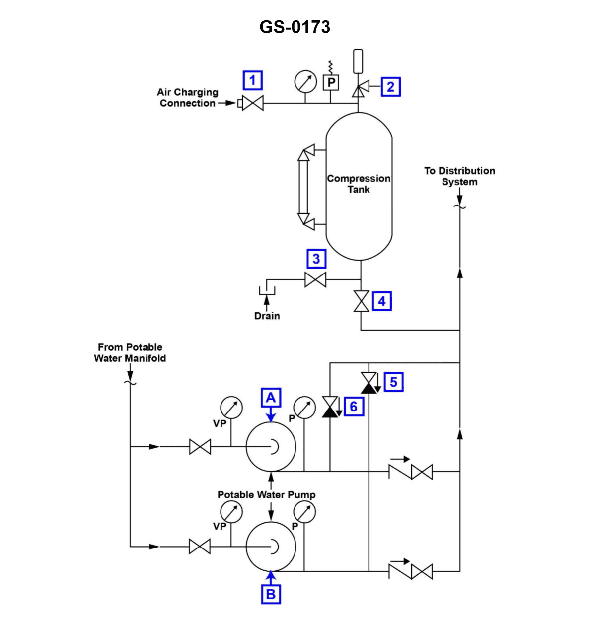
Question: According to the illustration, which of the following conditions would most likely cause pump "A" to short cycle? Illustration GS-0173
A. The hydro-pneumatic expansion tank is operating with an insufficient air charge.
B. The hydro-pneumatic tank is operating with a low water level.
C. A low water level exists in the potable water storage tank.
D. Pump "A" wearing rings have excessive clearance.
The Correct Answer is A **Explanation for Option A (Correct):** Short cycling in a constant pressure booster system occurs when the pressure drops quickly, causing the pump to start (cut-in), and then the pressure recovers too quickly, causing the pump to stop (cut-out). The hydro-pneumatic expansion tank is designed to provide a pressure buffer and store enough water (known as the effective draw-down volume) to prevent rapid pressure fluctuations. If the hydro-pneumatic tank has an **insufficient air charge**, the effective volume of water that can be stored between the pump cut-in pressure and cut-out pressure is dramatically reduced. When the system draws even a small amount of water, the pressure rapidly drops to the cut-in setting. The pump starts, but because the compressed air cushion is missing, the small amount of water the pump delivers immediately brings the pressure back up to the cut-out setting, causing the pump to stop almost instantly. This rapid and frequent starting and stopping is short cycling. **Why other options are incorrect:** * **B) The hydro-pneumatic tank is operating with a low water level:** A low water level in the hydro-pneumatic tank usually implies that the tank is overly charged with air (or nitrogen), or that the pump is struggling to maintain pressure. A low water level means the air volume is large, which provides a larger cushion and a larger effective draw-down volume, which would typically *reduce* short cycling, not cause it. * **C) A low water level exists in the potable water storage tank:** This tank supplies water to Pump A. If the level is too low, Pump A would likely starve for suction (cavitation) or shut off due to a low suction pressure safety switch. While this is a serious operational fault, it does not create the characteristic rapid pressure oscillation between the cut-in and cut-out settings associated with short cycling of the pressure control system. * **D) Pump "A" wearing rings have excessive clearance:** Excessive clearance in wearing rings results in internal leakage (recirculation) within the pump. This reduces the pump's efficiency and capacity (head/pressure achieved). This condition would make it harder for the pump to reach the cut-out pressure, potentially causing the pump to run *longer* or continuously, but it is not the primary mechanism that causes the rapid, frequent start/stop action of short cycling linked to pressure buffer failure.
Question 30
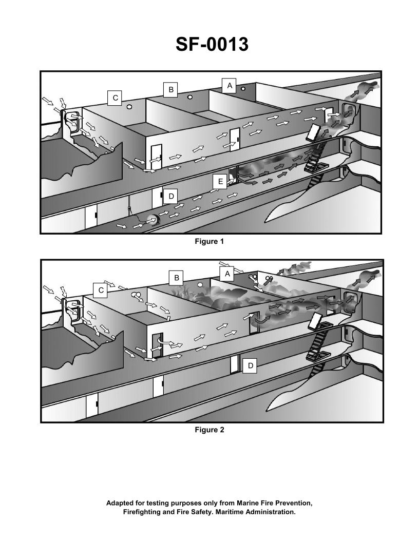
Question: What is the purpose of opening the doors and portholes in figure 2 of the illustration? Illustration SF-0013
A. To keep the hose teams cool
B. To allow water used to fight the fire to flow out of the superstructure
C. To allow venting of combustion products from the fire to the atmosphere
D. To provide air flow around the compartment in order to contain the fire
The Correct Answer is C **Explanation for C (Correct Option):** Option C, "To allow venting of combustion products from the fire to the atmosphere," is the correct purpose for intentionally opening doors and portholes during firefighting operations in a ship's superstructure (as suggested by the context of illustration SF-0013, which likely depicts fire control measures). This process is known as **ventilation** or **venting**. Controlled ventilation is critical because it: 1. **Removes Heat and Toxic Gases:** Allows superheated smoke, poisonous combustion products (like carbon monoxide), and trapped thermal energy to escape. 2. **Improves Firefighting Conditions:** By venting smoke and heat, visibility is increased, and the temperature within the compartment is lowered, making it safer and more effective for personnel to enter and fight the fire directly (interior attack). 3. **Controls Fire Spread (When done correctly):** Venting the fire compartment *before* entry (or simultaneously) can guide the flow of the fire and combustion products away from unaffected areas. **Explanation of Incorrect Options:** * **A) To keep the hose teams cool:** While venting *does* lower the temperature within the fire area (which benefits the hose teams), cooling the compartment is a **secondary effect** and not the primary *purpose* of opening boundaries to the atmosphere. The primary purpose is the removal of the heat and smoke (combustion products). Hose teams primarily stay cool via the application of water and protective gear. * **B) To allow water used to fight the fire to flow out of the superstructure:** This refers to dewatering. While dewatering is a necessary post-fire or concurrent activity to maintain stability, the opening of doors and portholes specifically for controlled ventilation is generally done high up in the compartment (at the natural exhaust path) to remove heat and smoke. Dewatering openings are typically specialized scuppers or are created low in the compartment to manage accumulated firefighting water, and this is a separate stability/damage control concern from ventilation. * **D) To provide air flow around the compartment in order to contain the fire:** Providing airflow (oxygen) to a fire is generally the opposite of containing it; fire requires oxygen to burn. Uncontrolled introduction of fresh air (oxygen) through openings can intensify the fire and potentially lead to a rapid expansion event (like a backdraft or flashover). While controlled ventilation *does* introduce air, its immediate purpose is to **remove combustion products** and lower pressure/temperature, not simply to "provide air flow to contain the fire." Fire containment relies on establishing fire boundaries (closing doors and sealing openings), not increasing airflow. Controlled ventilation is used to manage the fire's behavior, not to contain it through airflow.
Question 33
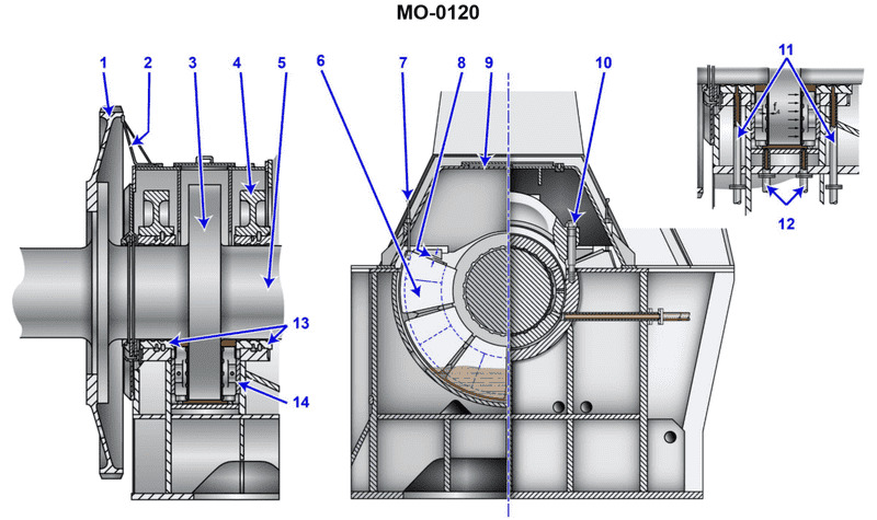
Question: What prevents the thrust bearing blocks shown in the illustration from rotating within the housing? Illustration MO-0120
A. Found within the thrust bearing cap or cover are extended protrusions to position the thrust shoe segments and maintain minimum clearance.
B. The bearing blocks are massive and their weight provides sufficient force to prevent rotation.
C. The thrust shoes are dovetailed into the collar.
D. The bearing assembly is specifically designed to allow for rotation, permitting the transmittal of axial forces across a greater surface area and minimizing loading densities.
The Correct Answer is A. **Why Option A is Correct:** Option A describes the standard mechanical constraint mechanism used in many multi-segment or segmented thrust bearings (often referred to as Kingsbury or Mitchell type bearings). The bearing segments, or "shoes," must be held securely in place relative to the housing to transmit the axial load effectively without rotation. To achieve this, the housing, bearing cap, or cover incorporates specific features (like pins, dowels, keys, or extended protrusions) that fit into corresponding recesses or slots on the back of the thrust shoes. These protrusions prevent the thrust shoe segments from following the rotating shaft (rotation within the housing) while still allowing the critical tilting motion necessary for forming the hydrodynamic oil wedge. Maintaining the position also ensures the proper operational clearance is maintained. **Why the Other Options Are Incorrect:** * **B) The bearing blocks are massive and their weight provides sufficient force to prevent rotation.** This is incorrect. While thrust bearing components can be substantial, reliance on weight (gravity) alone is insufficient and unreliable for preventing rotation, especially given the high torque and oil film formation that effectively reduces friction. Mechanical keys or stops are always required. * **C) The thrust shoes are dovetailed into the collar.** This is incorrect. The thrust shoes (bearing segments) ride against the rotating collar (or runner). They must be secured to the **stationary housing**, not the rotating collar. If they were attached to the collar, they would rotate with the shaft and would not function as a stationary bearing surface. * **D) The bearing assembly is specifically designed to allow for rotation, permitting the transmittal of axial forces across a greater surface area and minimizing loading densities.** This is incorrect. The purpose of the **thrust shoes** is to provide a **stationary** surface against the rotating collar to transmit the axial force to the machine frame. Allowing the thrust shoes themselves to rotate would negate their function as a stationary bearing and prevent the proper formation of the critical hydrodynamic oil wedge necessary for operation.
Question 33
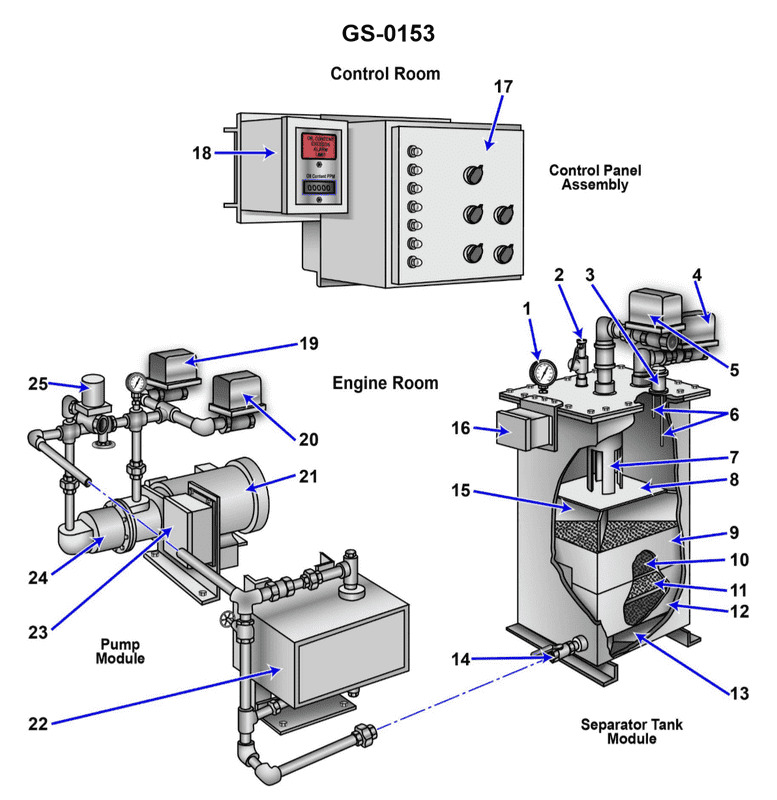
Question: What is the normal direction of flow through the device shown in the illustration while operating in the processing mode? Illustration GS-0153
A. The oily-water mixture enters through the pressure control valve "2" and exits with the processed liquid through valve "14".
B. The oily-water mixture enters through valve "4" and exits as processed liquid through valve "14".
C. The oily-water mixture enters through valve "5" and exits the separator through valve "14" as processed liquid.
D. The oily-water mixture enters through valve "14" and exits with the processed liquid through valve "4".
The Correct Answer is C. **Explanation for C (Correct):** The illustration GS-0153 typically depicts a standard marine oily water separator (OWS), often a centrifugal or gravity-based separator. In its normal operating (processing) mode, the function is to take the raw bilge water mixture and separate the oil content from the water content. The normal flow path for the mixture to be processed is: 1. **Inlet:** The raw oily-water mixture is pumped into the separator unit. Valve **5** is the designated inlet valve for the raw, contaminated bilge water. 2. **Processing:** The mixture is processed within the separator (using gravity, coalescers, or centrifugal force). 3. **Outlet:** The cleaned (processed) water, which meets discharge regulations (e.g., < 15 ppm oil content), is discharged overboard or sent to a holding tank. Valve **14** is universally positioned as the outlet valve for the processed, cleaned water (processed liquid). Therefore, the flow is correctly described as entering through valve 5 and exiting through valve 14. **Explanation of Incorrect Options:** * **A) The oily-water mixture enters through the pressure control valve "2" and exits with the processed liquid through valve "14".** Valve **2** is typically a pressure control valve (regulating the pressure within the separator or discharge line) or an air vent/backflushing connection, not the primary inlet for the main oily-water mixture flow. Valve 5 is the standard inlet. * **B) The oily-water mixture enters through valve "4" and exits as processed liquid through valve "14".** Valve **4** is commonly identified as the oil discharge valve (where the separated oil is drawn off and sent to a sludge tank) or a recirculation line, not the main inlet for the raw mixture. Valve 5 is the inlet. * **D) The oily-water mixture enters through valve "14" and exits with the processed liquid through valve "4".** This reverses the entire process flow. Valve **14** is the outlet for the processed water, and valve **4** is usually the oil outlet or a control line, not the main processed water outlet.
Question 34
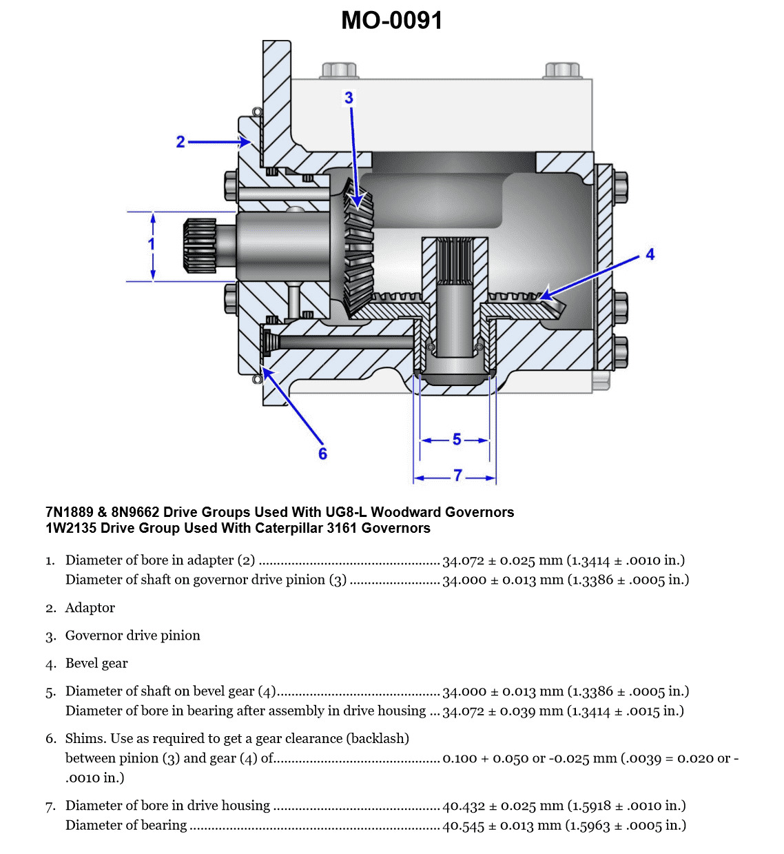
Question: The gear drive, shown in the illustration, can have the backlash determined best by using a __________. Illustration MO-0091
A. Lash indicator
B. Lead wire
C. Red dye indicator
D. Feeler gauge
The Correct Answer is D **Explanation for Option D (Feeler gauge):** A feeler gauge is a simple, precise measuring tool consisting of a set of blades of known thickness. When determining the backlash (the clearance or play between mating gear teeth), a feeler gauge is the most common and practical tool used, particularly for static measurements or verification of the set clearance in smaller gearboxes or differential assemblies. The gear teeth are held against one flank, and the feeler gauge is inserted into the gap (backlash) between the opposite flanks of the mating teeth to directly measure the clearance. **Explanation for Incorrect Options:** * **A) Lash indicator:** While "lash" is a synonym for backlash, a "lash indicator" is not a standard, recognized precision measuring tool name in the same way a dial indicator or feeler gauge is. Backlash is typically measured using a dial indicator (often called a "dial indicator with magnetic base") for highly precise dynamic measurements, or a feeler gauge for static checks. * **B) Lead wire:** Lead wire (or Plastigage) is a crushable material used to measure the **clearance** between two loaded bearing surfaces, such as a crankshaft journal and a bearing cap, by measuring how much the wire flattens when the surfaces are torqued together. It is completely unsuitable for measuring the lateral or tangential clearance between gear teeth (backlash). * **C) Red dye indicator:** Red dye penetrant is a method used for **Non-Destructive Testing (NDT)** to detect surface cracks or flaws in materials. It has no application in measuring dimensional clearance like backlash.

Question 35
Question: The vessel to which you are assigned is fitted with a totally pneumatic propulsion control system as shown in the illustration. If propulsion control functions perfectly from the engine room control station, but will not function at all from any of the remote stations, which of the following system faults best accounts for these symptoms? Illustration MO-0168
A. The local/remote transfer valve at the engine room control station has a blocked local port.
B. The attendance valve at the pneumatic remote-control station has a blocked outlet port.
C. The local/remote transfer valve at the engine room control station has a blocked remote port.
D. The pilot house/remote transfer valve at the pilot house has a blocked remote port.
The Correct Answer is C **Why option C is correct:** The system is described as having a totally pneumatic propulsion control system. The key symptoms are: 1. Propulsion control functions **perfectly** from the Engine Room (ER) control station (Local Control). 2. Propulsion control **will not function at all** from any of the Remote stations (e.g., Bridge/Pilot House). Pneumatic control systems typically use a "Local/Remote" transfer valve in the engine room (the primary location) to switch control authority. For the remote stations to function, the ER station must be set to "Remote." When set to "Remote," the valve must allow the control signal (air pressure) originating from the remote station (Bridge) to pass through the ER station and onward to the main engine governor/actuator. If the **remote port** on the local/remote transfer valve in the ER is blocked (Option C), the following happens: * If the valve is set to "Local," the ER station can still operate the engine perfectly, confirming that the local side (engine room components) is functional. (Matches symptom 1). * If the valve is set to "Remote," the signal air coming from the Bridge/Remote station cannot pass through the blocked port in the ER valve to reach the engine. Therefore, no remote control is possible. (Matches symptom 2). This single fault perfectly isolates the remote control pathway at the critical transfer point (the ER station) while leaving the local control pathway fully operational. **Why the other options are incorrect:** * **A) The local/remote transfer valve at the engine room control station has a blocked local port.** If the local port were blocked, the engine could not be controlled from the Engine Room, even if the valve were set to "Local." Since the prompt states control functions perfectly from the ER, this is incorrect. * **B) The attendance valve at the pneumatic remote-control station has a blocked outlet port.** The "attendance valve" (or similar safety switch) is typically a component located at one specific remote station (e.g., the bridge). If only this single station's valve were blocked, control would fail only from that specific station, but other remote stations (if they exist, such as an emergency remote station) might still function. More importantly, this does not account for the total failure of *all* remote stations while Local control remains perfect, which points to a common failure point like the main ER transfer valve. * **D) The pilot house/remote transfer valve at the pilot house has a blocked remote port.** A transfer valve in the Pilot House/Bridge typically allows the operator to switch control between the Pilot House console and another designated secondary remote location (if fitted). If the remote port on the Pilot House valve were blocked, it would only prevent control from the secondary remote station being utilized via the Pilot House, but it would not prevent the Pilot House itself (the primary remote station) from sending a signal, nor would it affect other potential remote stations. Furthermore, this localized fault would not prevent the ER station from receiving the signal if it were functioning correctly, nor would it explain why the signal fails to reach the engine, as the ultimate common failure point for all remote signals is the ER transfer valve.
Question 36
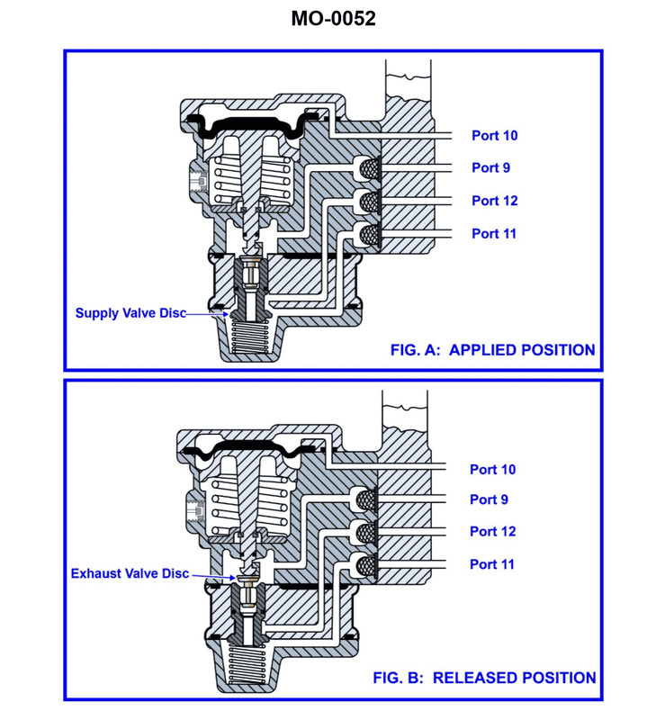
Question: The pneumatic propulsion control system used on your vessel uses a diaphragm-operated relay valve as shown in the illustration. Periodically, the valve is to be disassembled for cleaning and inspection. What statement best describes the proper technique? Illustration MO-0052
A. Rubber parts such as the diaphragm and metal parts such as the valve discs and seats should all be washed with soap and water.
B. Rubber parts such as the diaphragm should be washed with soap and water, and metal parts such as the valve discs and seats should be cleaned with non-flammable solvent.
C. Rubber parts such as the diaphragm and metal parts such as the valve discs and seats should all be cleaned with non-flammable solvent.
D. Rubber parts such as the diaphragm should be cleaned with non-flammable solvent, and metal parts such as the valve discs and seats should be washed with soap and water.
The Correct Answer is B **Explanation of Correctness (Option B):** Option B provides the best practice for cleaning components in a diaphragm-operated pneumatic relay valve. 1. **Rubber Parts (Diaphragm):** Diaphragms are typically made of synthetic rubber or elastomer material. These materials are sensitive to harsh solvents (especially petroleum-based or highly volatile ones), which can cause them to swell, degrade, lose flexibility, or crack. The recommended cleaning method for rubber parts is washing gently with mild soap and water, followed by careful drying. 2. **Metal Parts (Valve Discs and Seats):** Metal parts, such as the valve body, discs, and seats, often accumulate hardened deposits, oil residue, and fine particulate matter. A non-flammable solvent (like specialized industrial cleaning fluids or degreasers, or sometimes isopropyl alcohol depending on the application) is highly effective at dissolving these residues quickly without leaving residue themselves, ensuring a perfectly clean sealing surface for reliable valve operation. **Explanation of Incorrect Options:** * **A) Rubber parts such as the diaphragm and metal parts such as the valve discs and seats should all be washed with soap and water.** While safe for rubber, soap and water are often insufficient for removing tenacious oil, grease, or sticky deposits from precision metal seating surfaces, potentially leaving residues that could interfere with sealing or cause sticking. * **C) Rubber parts such as the diaphragm and metal parts such as the valve discs and seats should all be cleaned with non-flammable solvent.** Using solvents on rubber parts (the diaphragm) poses a significant risk. Even "non-flammable" industrial solvents may contain chemicals that attack, soften, or swell the rubber material, leading to premature failure, loss of responsiveness, or inaccurate control. * **D) Rubber parts such as the diaphragm should be cleaned with non-flammable solvent, and metal parts such as the valve discs and seats should be washed with soap and water.** This option reverses the correct procedures. Cleaning the rubber diaphragm with solvent is hazardous (as noted above), and cleaning the metal seating surfaces with only soap and water is generally ineffective for thorough degreasing and deposit removal.
Question 36
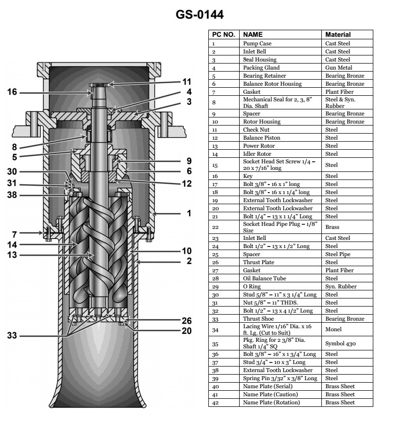
Question: What type of pump is shown in the illustration? Illustration GS-0144
A. Deep well centrifugal pump
B. Double screw rotary pump
C. Triple screw rotary pump
D. Simplex reciprocating pump
The Correct Answer is C ### Explanation for Option C (Triple screw rotary pump) Illustration GS-0144 typically depicts a positive displacement pump characterized by three intermeshing helical rotors (screws) encased within a housing. These rotors consist of a central drive screw and two surrounding idler screws. The rotational motion of the screws traps the fluid within the cavities formed between the threads and the housing wall, smoothly propelling the fluid axially from the suction side to the discharge side without pulsation. This specific configuration, featuring three distinct screws, defines it as a **Triple screw rotary pump**. *** ### Explanation of Why Other Options Are Incorrect **A) Deep well centrifugal pump:** This type of pump uses rotating impellers to impart kinetic energy to the fluid, which is then converted into pressure by a diffuser. It operates based on hydrodynamics, not positive displacement using meshing screws. Visually, it appears as a long, multi-stage cylindrical assembly. **B) Double screw rotary pump:** While similar in principle, a double screw pump uses only two intermeshing screws. The illustration (GS-0144) specifically shows the three-screw configuration (one power rotor and two idler rotors) necessary to balance the hydraulic forces and define the triple-screw type. **D) Simplex reciprocating pump:** A reciprocating pump uses a piston, plunger, or diaphragm that moves linearly back and forth (reciprocates) inside a cylinder to move fluid. This mechanism is fundamentally different from the continuous rotary motion used by a screw pump, and the visual appearance would involve a crank, connecting rod, and valves.
Question 45
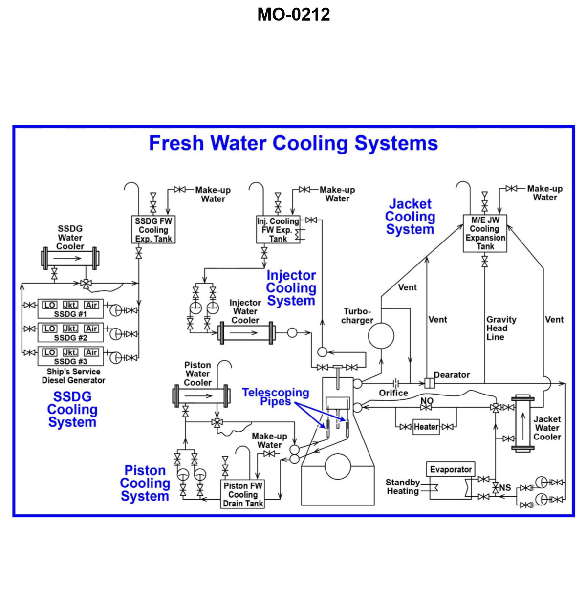
Question: Referring to the illustrated motorship freshwater cooling system drawing, which cooling system tanks are MOST likely to have oil separation capability? Illustration MO-0212
A. Injector cooling water tank and main engine jacket water cooling expansion tank.
B. Injector cooling water tank and piston cooling water drain tank.
C. Piston cooling water drain tank and main engine jacket water cooling expansion tank.
D. SSDG freshwater expansion tank and main engine jacket water cooling expansion tank.
The Correct Answer is B. ### Explanation for why Option B is Correct: Option B, "Injector cooling water tank and piston cooling water drain tank," is the most likely answer because these two tanks handle water that has been in close proximity to moving parts and potential lubrication oil sources, necessitating oil separation capability. 1. **Piston Cooling Water Drain Tank:** The piston cooling water circulates through the piston crowns, which are located directly above the crankcase (containing lube oil) and near the piston rod stuffing box (where oil and water barriers are maintained). While freshwater is generally used, slight leakages from the stuffing box or contamination pathways can introduce lubrication oil (lube oil or cylinder oil) into the cooling water. Therefore, the drain tank must be equipped with features (like baffles, settling volume, or dedicated separation outlets) to allow any contaminating oil to separate by gravity for inspection or removal before the water is treated or recirculated. 2. **Injector Cooling Water Tank:** The injectors (fuel valves) are lubricated by the fuel oil itself and are situated within the combustion space environment. Although the cooling system is separate, the injectors operate under intense heat. Contamination of the injector cooling water tank is a critical concern, often involving both combustion byproducts (soot) and potentially small amounts of fuel or lubricating oil from seals or operational pathways. Maintaining clean injector cooling water is essential for preventing injector damage. Therefore, this tank is often designed as a header or drain tank with features to allow oil (which is less dense) and sometimes particulate matter to settle or separate. ### Explanation for why other options are Incorrect: **A) Injector cooling water tank and main engine jacket water cooling expansion tank.** While the Injector cooling water tank is likely to have separation capability (as explained above), the **main engine jacket water cooling expansion tank** primarily serves as a pressure compensation, thermal expansion volume, and vent point for the jacket water system (cooling the cylinder liners and head). The jacket water system is typically a closed loop that is well-separated from oil sources. While minor contamination is possible, the primary function of the expansion tank is not dedicated oil separation; separation capability is much more critical for drain tanks like the piston cooling water drain tank. **C) Piston cooling water drain tank and main engine jacket water cooling expansion tank.** The **piston cooling water drain tank** is correct. However, the **main engine jacket water cooling expansion tank** is unlikely to be prioritized for significant oil separation capability compared to the tanks handling water that has passed through the internal engine components (like pistons and injectors) where oil contamination risk is highest. **D) SSDG freshwater expansion tank and main engine jacket water cooling expansion tank.** Both the **SSDG freshwater expansion tank** (Auxiliary Engine) and the **main engine jacket water cooling expansion tank** are involved in closed-loop jacket cooling systems. These systems are structurally separated from oil contamination risk (unlike piston/injector systems), making it highly improbable that either tank would be a primary location for required oil separation features.
Question 46
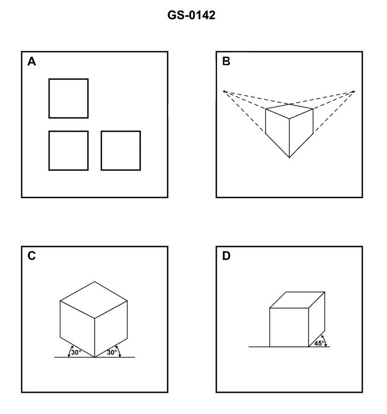
Question: Which of the figures shown in the illustration depicts an orthographic projection? Illustration GS-0142
A. A
B. B
C. C
D. D
The Correct Answer is A. **Explanation for Option A (A) being correct:** Figure A depicts an **orthographic projection**. An orthographic projection is a method of representing a three-dimensional object in two dimensions by using multiple views (usually front, top, and right side views) that are aligned and projected perpendicularly onto projection planes. The figure shows the front view, top view (aligned directly above the front view), and right side view (aligned directly to the right of the front view), where all parallel lines in the object are projected as parallel lines in the views, maintaining true size and shape relationships necessary for engineering drawings. **Explanation for Options B, C, and D being incorrect:** * **Option B (B) is incorrect** because Figure B depicts an **isometric projection** (a type of axonometric projection). In this view, the three axes (height, width, depth) are typically shown meeting at a single point, with the angle between them often being $120^\circ$. It represents the object in a single pictorial view rather than multiple flat views required for orthographic projection. * **Option C (C) is incorrect** because Figure C depicts an **oblique projection** (specifically, a cavalier or cabinet projection). In this view, one face (usually the front) is shown in true size and shape, while the depth lines recede at an angle (often $30^\circ$ or $45^\circ$) and may or may not be drawn to true length, creating a pictorial, three-dimensional representation. * **Option D (D) is incorrect** because Figure D depicts a **perspective projection** (specifically, a one-point perspective). This method creates the most realistic visual effect by using vanishing points, where parallel lines appear to converge as they recede into the distance. This is fundamentally different from the parallel line projections used in orthographic drawings.
Question 47
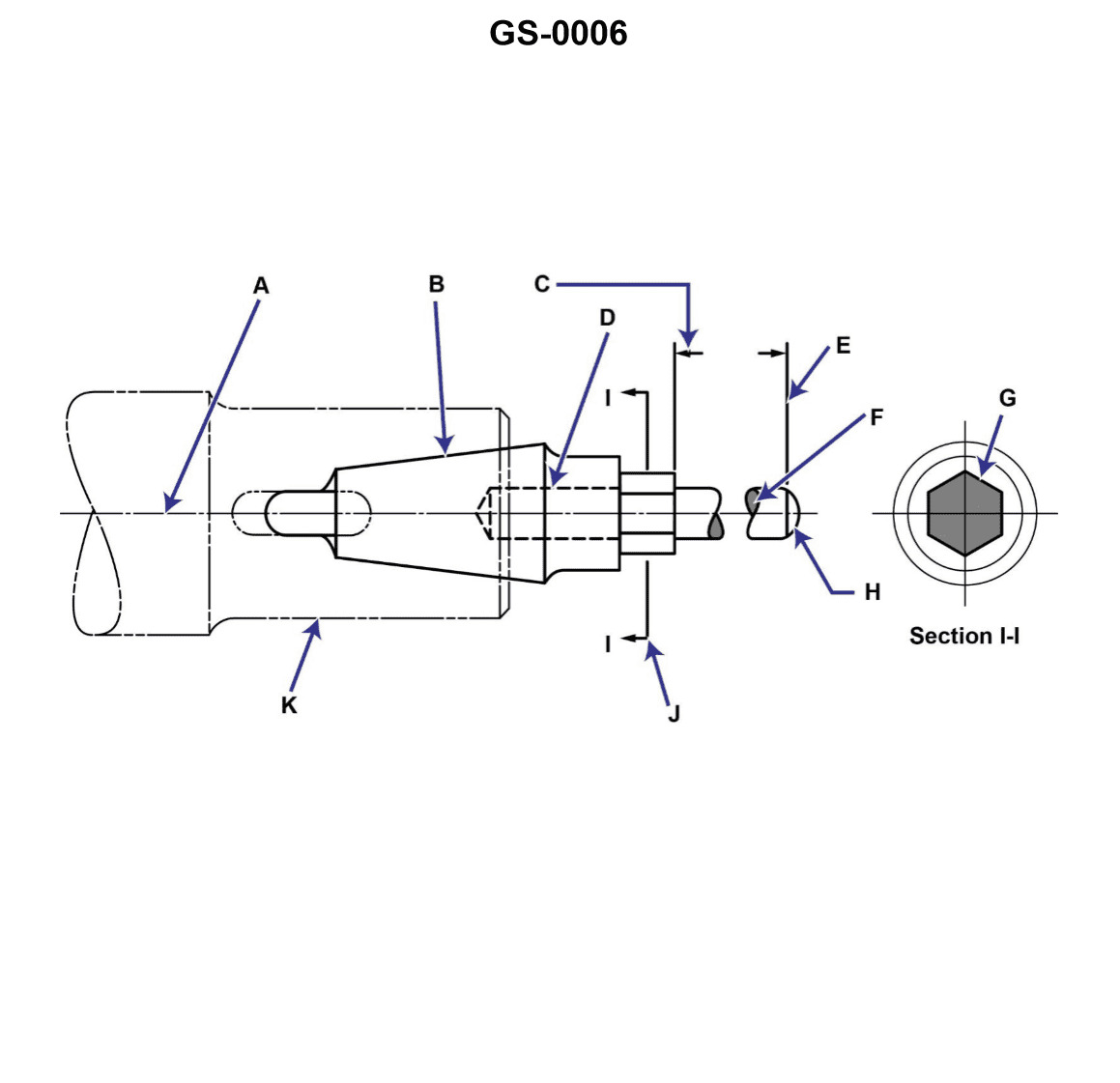
Question: In the illustration, line "C" is a __________. Illustration GS-0006
A. dimension line
B. leader line
C. cutting plane line
D. phantom line
The Correct Answer is A **Explanation for Option A (dimension line):** In technical drawing and illustrations like the one referenced (GS-0006, which typically shows orthographic or section views), a **dimension line** is used to indicate the extent of a measurement (the dimension). It is a thin, solid line terminated by arrowheads, tick marks, or dots, placed parallel to the distance being measured. Line "C," situated between two extension lines and terminated by arrowheads pointing to the object features, is the standard representation for communicating a specific length or size, making it a dimension line. **Explanation for Incorrect Options:** * **B) leader line:** A leader line is a thin, solid line used to direct attention from a note or dimension to the specific feature on the drawing to which it applies. It usually terminates in an arrowhead touching the feature and has a horizontal shoulder near the text. Line "C" is measuring a distance, not pointing to a note, so it is not a leader line. * **C) cutting plane line:** A cutting plane line (or viewing plane line) is a heavy line composed of alternating long dashes and pairs of short dashes (or specific patterns like long dash/double short dash). It indicates where a section view is taken. Line "C" does not match this pattern and is not used to define a sectional cut. * **D) phantom line:** A phantom line is a thin line consisting of one long dash alternating with two short dashes. It is used to show alternate positions of a moving part, repetitive features, or the outline of adjacent parts. Line "C" is a standard dimension marker and does not represent an alternate position or adjacent structure.
Question 48
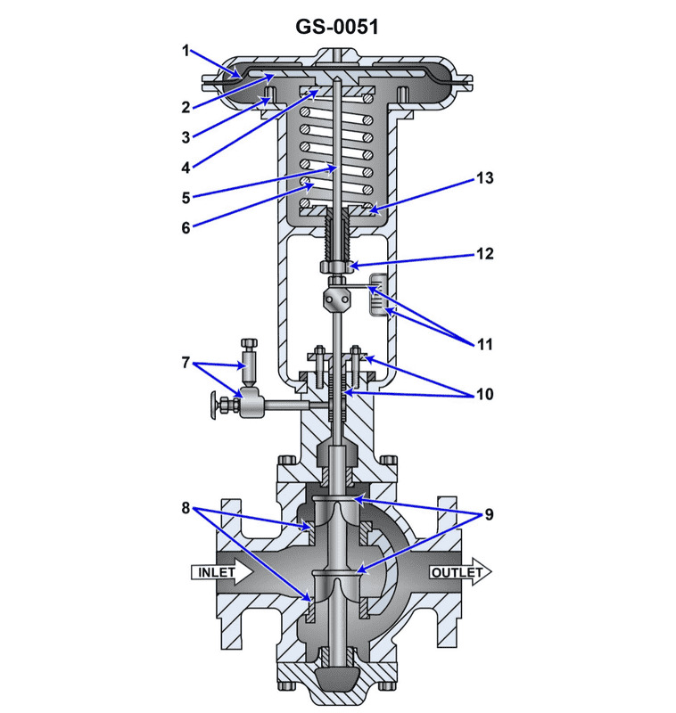
Question: Suppose the illustrated pneumatically operated diaphragm actuated control valve is used to control the fuel oil outlet temperature of a steam-heated heavy fuel oil heater by controlling the steam flow. What would be the result if there was a complete loss of pilot air being delivered to the valve actuator? Illustration GS-0051
A. The valve would fail in the fully open position, most likely resulting in a high fuel oil temperature alarm condition.
B. The valve would fail in the fully closed position, most likely resulting in a low fuel oil temperature alarm condition.
C. It is not possible to predict how the valve would respond to a loss of pilot air.
D. The valve would fail in the exact position just before the loss of pilot air. The fuel temperature will fluctuate with changes in fuel demand.
The Correct Answer is A **Explanation of Option A (Correct Answer):** 1. **Valve Type and Actuation:** The question describes a *pneumatically operated diaphragm actuated control valve*. Control valves are typically designed to fail safely (Fail-Open or Fail-Closed) upon loss of the actuating medium (in this case, pilot air). This behavior is determined by the internal spring mechanism. 2. **Application (Control Loop):** The valve is controlling the *steam flow* to a heavy fuel oil (HFO) heater to maintain the *fuel oil outlet temperature*. This is a temperature control loop. 3. **Determining the Fail-Safe Position:** To prevent damage or undesirable operating conditions, the valve must fail in the position that causes the *least risk*. * If the valve fails **closed (no steam)**, the HFO temperature will drop rapidly (low temperature alarm/viscosity issues). While undesirable, this is generally safer than overheating. * If the valve fails **open (full steam)**, the HFO temperature will spike dramatically (high temperature alarm/potential coking/safety hazard). 4. **Standard Industry Practice (Steam Supply Control):** When controlling the supply of heating medium (like steam) to a critical process fluid (like fuel oil), standard practice dictates that the control valve should be designed to be **Air-to-Close (ATO)**, meaning loss of air pressure causes the internal spring to push the diaphragm open. This design choice results in a **Fail-Open (FO)** position. Although failing open results in high temperature (Option A), in many boiler and fuel supply applications, a failure that risks high temperature is considered the intended failure mode (or the system has secondary safety trips to manage this high temperature, such as a high-limit thermostat or trip valve). 5. **Conclusion:** Assuming standard Fail-Open design (Spring to Open, Air to Close) for a steam control valve, a complete loss of pilot air removes the closing force. The spring overcomes atmospheric pressure, driving the valve to the fully open position. Full steam flow results in maximum heat transfer and a sharp rise in fuel oil temperature, causing a high-temperature alarm condition. **Explanation of Incorrect Options:** * **B) The valve would fail in the fully closed position, most likely resulting in a low fuel oil temperature alarm condition.** This would be the result if the valve were designed to be **Air-to-Open (Fail-Closed, FC)**. While some applications use FC for steam, the default setup for a standard diaphragm actuator controlling the heating medium in this context is often FO. If the valve were FC, the loss of air would cause the spring to close the valve, resulting in low temperature. However, given the failure dynamics of typical steam control systems, A is the more likely correct standard assumption. * **C) It is not possible to predict how the valve would respond to a loss of pilot air.** This is incorrect. All pneumatically actuated valves are specifically designed and configured (either Fail-Open or Fail-Closed) so that their response to a loss of air pressure is fully predictable based on the spring arrangement (pushing open or pushing closed). * **D) The valve would fail in the exact position just before the loss of pilot air. The fuel temperature will fluctuate with changes in fuel demand.** This is incorrect. A standard diaphragm actuator uses the pressure (pilot air) to compress a spring. When the pilot air pressure drops completely, the spring force is unopposed (or opposed only by the static process pressure) and immediately drives the stem fully to its free (fail-safe) position (either fully open or fully closed). It cannot hold an intermediate position without air pressure.
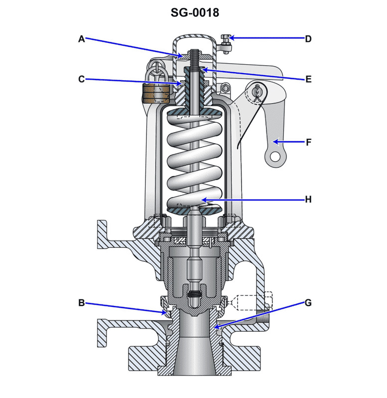
Question 49
Question: Referring to the illustrated huddling-chamber safety valve, what statement concerning the blowdown adjusting ring (B) is true? Illustration SG-0018
A. Raising the blowdown adjusting ring further increases the area of exposure to pressure after the valve pops and as a result, the valve blowdown will increase.
B. Raising the blowdown adjusting ring further decreases the area of exposure to pressure after the valve pops and as a result, the valve blowdown will decrease.
C. Raising the blowdown adjusting ring further increases the area of exposure to pressure after the valve pops and as a result, the valve blowdown will decrease.
D. Raising the blowdown adjusting ring further decreases the area of exposure to pressure after the valve pops and as a result, the valve blowdown will increase.
The Correct Answer is A **Explanation for Option A (Correct):** The blowdown adjusting ring (B) in a safety valve, particularly a spring-loaded pop-type valve, controls the amount of lift and the duration of the blowdown (the difference between the popping pressure and the reseating pressure). The valve is designed with a "huddling chamber" or "feathering lip" (the skirt of the valve disc) that traps the escaping fluid momentarily after the initial lift. The blowdown ring (B) controls the size of the annular opening, or nozzle, through which the steam (or other fluid) escapes from this chamber. * **Action:** Raising the blowdown adjusting ring (B) moves it further away from the valve disc (the feathering lip). * **Effect on Exposure Area:** This movement effectively increases the size of the escape nozzle and thus allows a larger area of the valve disc's skirt to be exposed to the high pressure escaping fluid immediately after the valve pops. * **Result on Blowdown:** The increased exposure area creates a greater downward force on the valve disc, holding the valve open longer. This requires the system pressure to drop to a lower point before the spring force can overcome the pressure force and reseat the valve. Therefore, **raising the ring increases the blowdown.** **Explanation of Incorrect Options:** * **B) Raising the blowdown adjusting ring further decreases the area of exposure to pressure after the valve pops and as a result, the valve blowdown will decrease.** This is incorrect. Raising the ring increases the exposure area, which in turn increases the blowdown, not decreases it. * **C) Raising the blowdown adjusting ring further increases the area of exposure to pressure after the valve pops and as a result, the valve blowdown will decrease.** This is incorrect. While the first part of the statement is true (raising the ring increases the exposure area), the conclusion is false. Increased exposure area prolongs the opening time and **increases** the blowdown. * **D) Raising the blowdown adjusting ring further decreases the area of exposure to pressure after the valve pops and as a result, the valve blowdown will increase.** This is incorrect. Raising the ring **increases** the exposure area, and although the conclusion (blowdown will increase) is correct, the reason provided (decreasing the area) is factually opposite to the design function of the ring adjustment.
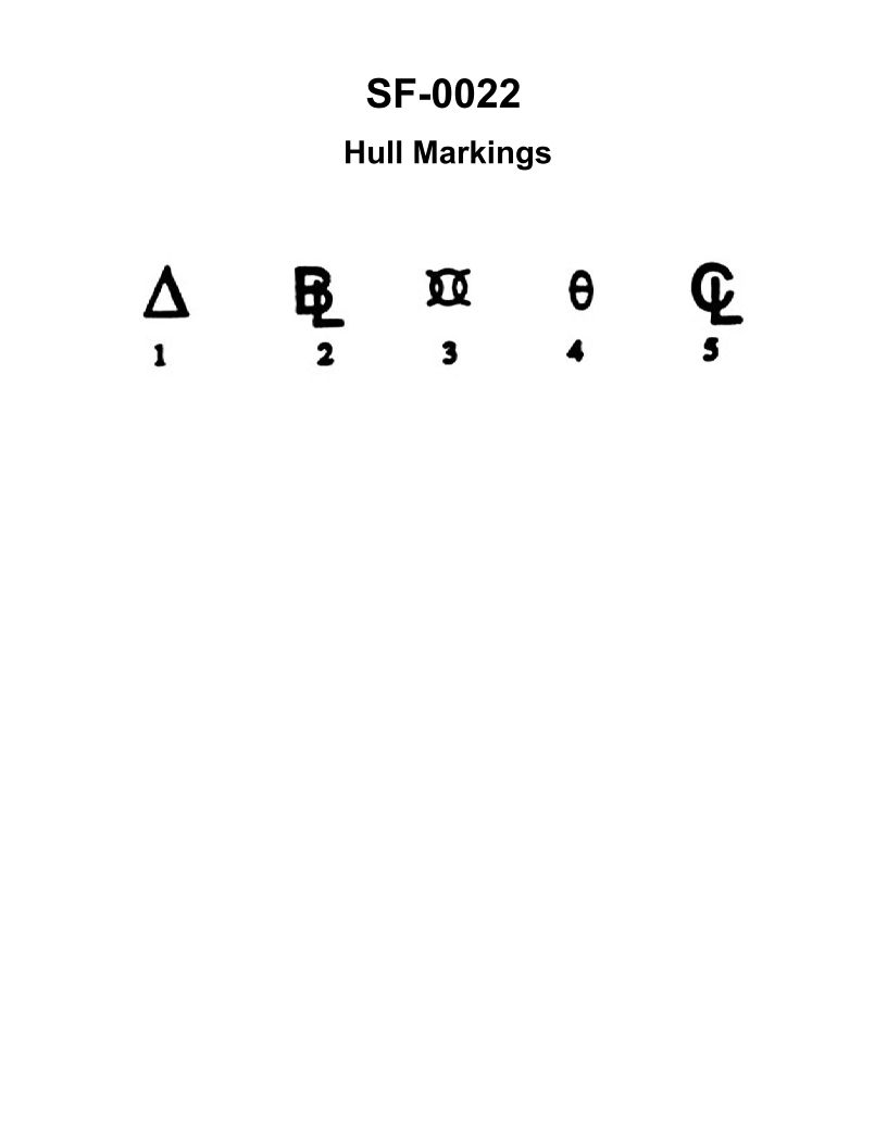
Question 50
Question: Symbol number "3" shown in the illustration represents which of the following? Illustration SF-0022
A. Displacement
B. Baseline
C. Amidships
D. Forward perpendicular
The Correct Answer is C **Explanation for Option C (Amidships):** The illustration SF-0022 (a typical diagram showing ship dimensions and lines) uses numerical labels to denote specific points or features. The label "3" in these diagrams typically points to the longitudinal center point of the vessel's length between perpendiculars (LBP). This midpoint is defined as the location **Amidships**, which is a transversal plane halfway between the Forward Perpendicular (FP) and the Aft Perpendicular (AP). This line is critical for defining the center of the Load Waterline (LWL) and is often the reference point for calculating trim and stability. **Why the other options are incorrect:** * **A) Displacement:** Displacement is the weight of the water the ship displaces, equal to the ship's weight. It is a value (mass or volume), not a point or line shown as "3" in the ship's profile diagram. * **B) Baseline:** The Baseline is the horizontal line at the lowest point of the molded body of the ship, usually coinciding with the top of the keel plate. While a key reference line, it is horizontal and located at the bottom of the hull, not the vertical midpoint labeled "3". * **D) Forward perpendicular (FP):** The Forward Perpendicular is a vertical line drawn through the intersection of the stem and the Load Waterline (LWL). It is one end point of the LBP, not the center point labeled "3".