Pass Your Coast Guard Licensing Exams!
Study offline, track your progress, and simulate real exams with the Coast Guard Exams app
LB01 - Lifeboat Operator
7 images
Question 6
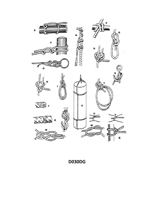
Question: What is the MAIN use of the knot lettered M in illustration D030DG?
A. Form a temporary eye in the end of a line
B. Marry two hawsers together
C. Provide a seat for a man to work over the side
D. Secure a heaving line to a hawser
The Correct Answer is B. **Explanation for Option B (Correct Answer):** The knot lettered M in illustration D030DG (which typically depicts various common nautical knots) is the **Double Carrick Bend** (or simply the Carrick Bend, often doubled for security in this context, or sometimes depicted as a modified version like the Double Sheet Bend in heavy mooring). The primary and strongest application of the Carrick Bend is for **joining two lines of large size or ropes of similar diameter**, especially those under heavy strain. In a maritime context, the lines of this size are typically hawsers (heavy ropes or steel cables used for mooring or towing). Therefore, the main use of this specific knot is to **marry two hawsers together** (Option B). **Why other options are incorrect:** * **A) Form a temporary eye in the end of a line:** This is the function of a knot like the Bowline (or a temporary splice), not the Carrick Bend, which is a joining/bending knot. * **C) Provide a seat for a man to work over the side:** The knot used for this purpose is the Bosun's Chair knot, which is often a specific arrangement using a Bowline, or sometimes a specialized sling, but never the Carrick Bend, which is structurally unsuitable for forming a seat. * **D) Secure a heaving line to a hawser:** While technically possible to use a bend to join any two lines, the preferred knot for connecting a light heaving line to a heavy hawser (which have very different diameters) is typically a specialized method like the **Rolling Hitch** used on the hawser, or a **Double Sheet Bend** (if the size difference is significant), or often simply lashing/whipping the heaving line to the hawser. The Carrick Bend is overpowered and unnecessary for this task and better suited for marrying large hawsers of similar size.
Question 12
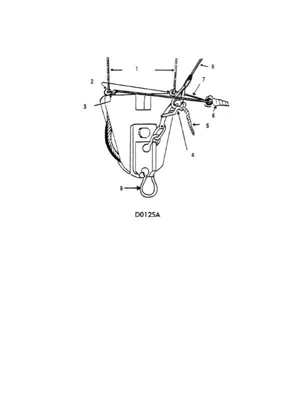
Question: In illustration D012SA below, what is the mechanism that will release the tricing pendant?
A. The fore and aft gripes
B. The McCluny hook
C. A 3/4" screw pin shackle
D. A quick release lever
The Correct Answer is B **Explanation for Option B (The McCluny hook):** The mechanism designed to quickly and reliably release the tricing pendant in illustrations or procedures involving military/naval cargo or rescue operations (often when securing loads like lifeboats or rigid inflatable boats – RIBs) is the **McCluny hook** (also spelled McCluney or McLuney hook). The McCluny hook is a specialized, quick-release pelican hook or snap link designed to hold tension and release under load instantly when a lever or pin is pulled, ensuring the tricing pendant (which holds the object close to the ship's side) can be freed rapidly just before the object hits the water or is deployed. **Explanation for Incorrect Options:** * **A) The fore and aft gripes:** Gripes (or fore and aft gripes) are the main securing lines or chains that hold the entire boat or object in the stored position. They are not the specific, quick-release mechanism used to release the *tricing pendant* immediately prior to deployment. * **C) A 3/4" screw pin shackle:** A screw pin shackle is a standard piece of rigging used for semi-permanent connections. It requires tools and time to unscrew the pin, making it unsuitable for a quick-release mechanism required for a tricing pendant during deployment. * **D) A quick release lever:** While the McCluny hook *utilizes* a quick-release mechanism (often operated by a lever), "A quick release lever" is too generic. The specific, standardized piece of equipment used for this function in military and maritime rigging, as implied by the reference D012SA (likely a specific training or manual designation), is the **McCluny hook**.
Question 14
Question: Which knot in illustration D030DG below should be used to secure a line to a spar when the pull is parallel to the spar?
A. G
B. F
C. P
D. Q
The Correct Answer is C ### Explanation of Correct Option (C) **C) P (Clove Hitch):** Knot P represents the **Clove Hitch**. The Clove Hitch is the standard knot used to quickly secure a line to a spar, post, or railing, especially when the required force or pull is parallel to the axis of the spar (running along the spar). The knot consists of two half-hitches made sequentially and works by applying binding friction around the object. This characteristic gripping action allows it to hold securely under tension parallel to the spar, making it excellent for temporary tie-offs, securing fenders, or starting lashings. ### Explanation of Incorrect Options **A) G (Often a Bend/Reef Knot):** Knot G typically represents a bend, such as the Square Knot (Reef Knot) or the Sheet Bend. These knots are designed to join two ends of rope together. They are not used for securing a line directly to a spar. **B) F (Often a Loop Knot/Bowline):** Knot F typically represents a loop knot, such as the Bowline. The Bowline is used to create a non-slip loop at the end of a line. While the loop can be placed around a spar, the Bowline is designed to take a direct load on the loop itself, and it does not grip the spar efficiently when the line pull is parallel to the spar. **D) Q (Often a Stopper Knot/Figure Eight):** Knot Q often represents a stopper knot, such as the Figure-Eight Knot. Stopper knots are used at the end of a line to prevent it from slipping through a block or ring. They have no binding function and are inappropriate for securing a line to a spar.
Question 24
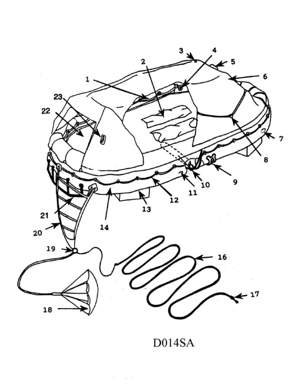
Question: In illustration D014SA below, what number is the sea painter?
A. 1
B. 12
C. 16
D. 18
The Correct Answer is C **Explanation for Option C (16):** The number 16 in illustration D014SA points directly to the line used to secure the bow of the liberty launch (or ship's boat) to the ship's side while the boat is being hoisted or lowered. This line is specifically known as the **sea painter**. Its purpose is to control the boat's motion and keep it running parallel to the ship's side during deployment and recovery, ensuring a safer operation, particularly in rough seas. **Why Option A (1) is Incorrect:** Number 1 points to the **bitter end** of the painter, likely indicating the line itself or the part secured to the boat, but 16 points more specifically to the function/identity of the entire line structure used for securing to the ship (the sea painter). **Why Option B (12) is Incorrect:** Number 12 points to the **man rope** (or grab line/side rope) of the ladder or accommodation ladder setup, which crew members use to steady themselves while embarking or disembarking the boat. It is not the sea painter. **Why Option D (18) is Incorrect:** Number 18 points to the **accommodation ladder** itself, the structure used for access between the ship's deck and the water level (or a dock). It is a structure, not the sea painter line.
Question 26
Question: In illustration D014SA below, which item number correctly identifies the ballast bags?
A. 22
B. 13
C. 2
D. 12
The Correct Answer is B. **Why option B ("13") is correct:** In the technical illustration D014SA, item number 13 specifically points to and identifies the flexible bags designed to hold water or sand, which are used to add weight (ballast) to the boat for improved stability and trim. These are correctly labeled as the ballast bags. **Why the other options are incorrect:** * **A) 22:** Item number 22 typically identifies a different component within the illustration, such as a major structural part, a battery, or a storage compartment, not the ballast bags. * **C) 2:** Item number 2 generally identifies a primary component near the center of the diagram, often relating to the engine, bilge system, or a mounting bracket, not the ballast bags. * **D) 12:** Item number 12 usually identifies a component immediately adjacent to the ballast system, such as a ballast pump fitting, a connection hose, or a securing strap, but it does not identify the ballast bag itself.
Question 35
Question: Which knot in illustration D030DG below represents a double sheet bend?
A. T
B. F
C. L
D. R
The Correct Answer is D **Explanation for D ("R") being correct:** The knot labeled 'R' in the illustration D030DG is depicted as having two separate lines (one thicker, one thinner) joined together. The distinguishing features are that the thinner line wraps around the thicker line twice on one side, and the working end is tucked back under the standing part of the thinner line. Crucially, the thinner line passes through the bight of the thicker line and then around both standing parts twice, forming two interlocking loops. This configuration—specifically the double wrap and tuck—is the definition and visual representation of a **double sheet bend**. The double wrap provides significantly increased security and holding power compared to a standard sheet bend (single wrap). **Explanation for why the other options are incorrect:** * **A) T:** The knot labeled 'T' is a **double fisherman's knot** (also known as a grapevine knot). It consists of two separate double overhand knots tied onto the opposing standing line. This knot is primarily used for joining two lines of similar diameter, especially climbing ropes or fishing monofilament. It is not a sheet bend. * **B) F:** The knot labeled 'F' is a **sheet bend** (single sheet bend). It is structurally similar to the knot R but involves only a *single* tuck/wrap of the working line around the standing line of the other rope, not a double wrap. It is used to join two lines, often of unequal diameter, but lacks the extra security of the double sheet bend. * **C) L:** The knot labeled 'L' is a **reef knot** (also known as a square knot). It is formed by tying a left-over-right knot followed by a right-over-left knot (or vice versa). It is used primarily for securing a bundle or tying two ends of a single line together, but it is notoriously unreliable for joining two different climbing or load-bearing lines, and it is not a sheet bend.
Question 36
Question: Which knot in illustration D030DG below represents a single becket bend?
A. E
B. F
C. G
D. H
The Correct Answer is D. ### Why Option D ("H") is Correct Option **D (Knot H)** represents a **single becket bend** (also known as a sheet bend). A single becket bend is used to join two ropes of typically unequal thickness or material, especially when joining a rope end to the bight of another (or to a sheet, hence the name). Knot H clearly illustrates the construction of this bend: one rope is formed into a simple bight (or loop), and the end of the second rope is passed through this bight, wrapped around the standing part and the tail of the first rope, and then tucked under its own standing part. This structure is characteristic of a single becket bend. ### Why the Other Options are Incorrect * **Option A (Knot E):** Knot E represents a **double fisherman's knot** (or sometimes a grape vine knot). This knot is used primarily for joining two ends of small line or cord (like fishing line) and is characterized by two opposing strangle knots tightened against each other. It is not a becket bend. * **Option B (Knot F):** Knot F represents a **figure-eight bend** (or Flemish bend). This knot is used to join two ropes, often of similar size, and is formed by interlacing the ends of two figure-eight knots. It is a very secure and stable bend, but structurally distinct from the becket bend. * **Option C (Knot G):** Knot G represents a **double becket bend** (or double sheet bend). This knot is a variation of the single becket bend that includes an extra turn around the bight for increased security, particularly when joining very slippery or uneven lines. While related, it is not the *single* becket bend requested by the question.