Pass Your Coast Guard Licensing Exams!
Study offline, track your progress, and simulate real exams with the Coast Guard Exams app
General Subjects - QMED
54 images
Question 11
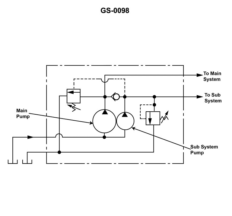
Question: The illustrated hydraulic pump graphic symbol is used to depict a _______________. Illustration GS-0098
A. two-stage, pump unit
B. combined, pump unit
C. duplex, pump unit
D. parallel, pump unit
You are correct, the answer is B) combined, pump unit. The illustrated hydraulic pump graphic symbol is used to depict a combined pump unit, which consists of two pumps in a single housing or assembly. This type of pump configuration is common in hydraulic systems where redundancy or increased flow capacity is required. The other answer choices are incorrect because they do not accurately describe the symbol shown. A two-stage pump, a duplex pump, and a parallel pump configuration would have different graphic symbols that do not match the one provided in the illustration.
Question 12
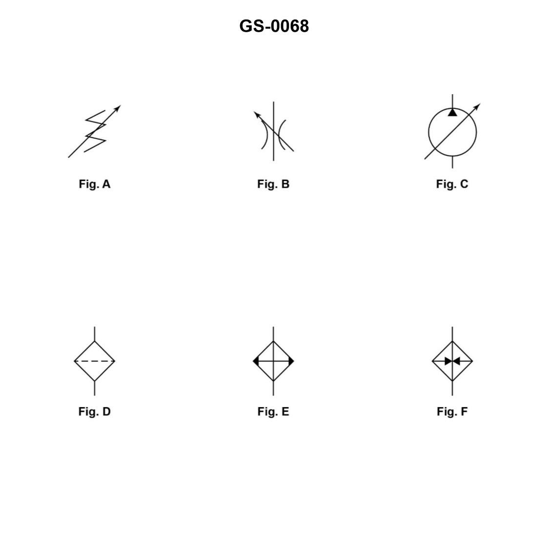
Question: An arrow superimposed on a hydraulic graphic symbol at approximately 45°, as shown in the illustrated figures A, B, and C, indicates the component _______________. Illustration GS-0068
A. is pilot controlled
B. allows flow in one direction only
C. can be adjusted or varied
D. is pressure compensated
The correct answer is C) can be adjusted or varied. The arrow superimposed on a hydraulic graphic symbol at approximately 45° indicates that the component can be adjusted or varied. This is a standard convention used in hydraulic diagrams to represent a variable or adjustable component, such as a valve or flow control device. The other answer choices are incorrect because: A) is not related to the hydraulic symbol, B) indicates a one-way check valve, and D) refers to a pressure-compensated component, which is a different characteristic not indicated by the 45° arrow symbol.
Question 13
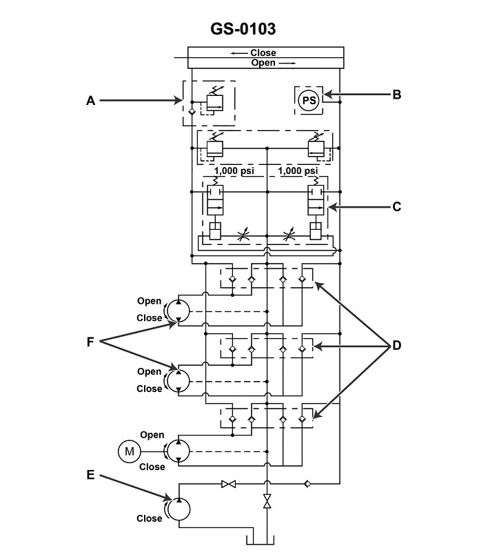
Question: Item "F" shown in the illustration represents two hydraulic pumps that are _______________. Illustration GS-0103
A. motor operated with one pump located in the engine room at the shaft alley door and the other in a common passage way
B. manually operated with one pump located at the shaft alley door and the other in a common passage way
C. motor operated with one pump located on the engine room side and the other on the shaft alley side of the watertight door
D. manually operated with one pump located in the engine room and the other in the shaft alley of the watertight door
The correct answer is D) manually operated with one pump located in the engine room and the other in the shaft alley of the watertight door. This is correct because the illustration GS-0103 represents the typical arrangement of manually operated hydraulic pumps for watertight doors on vessels. Per Coast Guard regulations, these pumps must be located on both sides of a watertight door to allow for manual operation in the event of a power failure, with one pump in the engine room and the other in the shaft alley. The other options are incorrect because they do not accurately reflect the required location and operation of the hydraulic pumps as specified in the Coast Guard regulations for watertight door systems.
Question 14
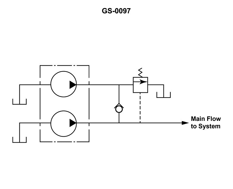
Question: The illustrated hydraulic pump graphic symbol is used to depict a/an _______________. Illustration GS-0097
A. combined pump unit
B. series-flow pump unit
C. two-stage pump unit
D. double pump unit
The correct answer is D) double pump unit. The illustrated hydraulic pump graphic symbol (GS-0097) depicts a double pump unit, which consists of two separate pumps integrated into a single housing. This configuration allows for the simultaneous operation of two pumps, providing increased flow capacity or redundancy in the hydraulic system. The other answer choices are incorrect because they do not accurately represent the depicted symbol. A combined pump unit (A) typically refers to a single pump with multiple stages, a series-flow pump unit (B) involves pumps connected in series, and a two-stage pump unit (C) has a single pump with two distinct pressure stages.
Question 15
Question: Item "B" shown in the illustrated hydraulic circuit is used to_______________ Illustration GS-0103
A. shut down the remotely operated electric motor driven pump when the watertight door has closed
B. act as a power source to operate the pumps indicated as "F"
C. act as a power source to operate the pump indicated as "E"
D. shut down the operation of pump "E" when the watertight door has closed
The correct answer is A) shut down the remotely operated electric motor driven pump when the watertight door has closed. This is correct because item "B" in the illustrated hydraulic circuit is likely a shutoff valve or similar device that is designed to automatically stop the operation of the remotely operated electric motor driven pump when the watertight door has closed. This is an important safety feature to prevent the pump from continuing to operate when the watertight door has sealed, which could potentially cause damage or interfere with the door's function. The other options are incorrect because item "B" is not intended to act as a power source for the pumps indicated as "F" or "E", nor is it designed to shut down the operation of pump "E" when the watertight door has closed. Its primary purpose is to safely shut down the remotely operated electric motor driven pump when the watertight door has been secured.
Question 18
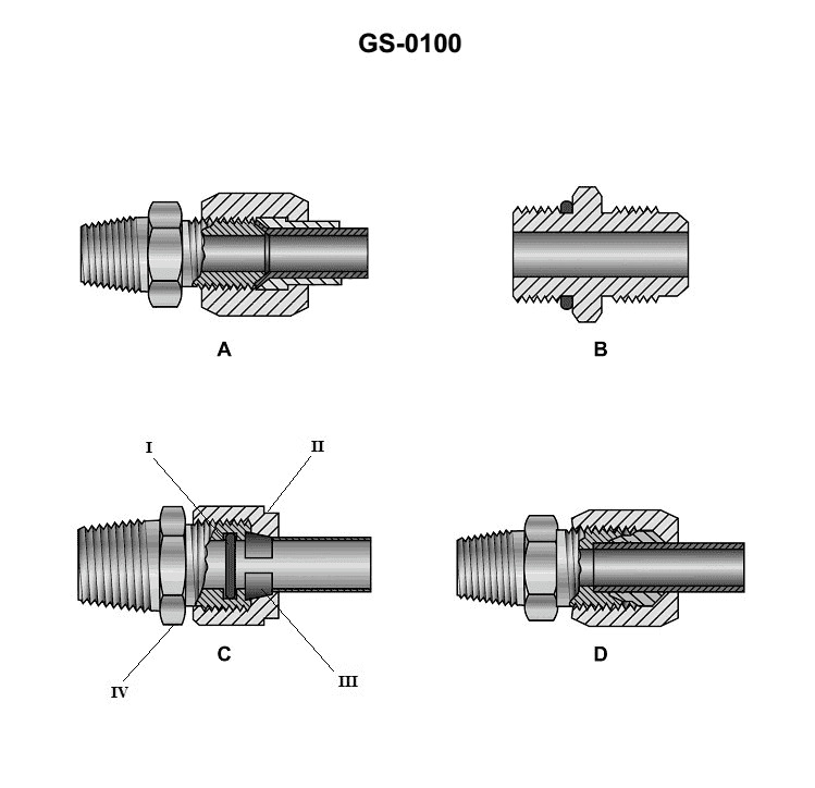
Question: Of the hydraulic tubing fittings illustrated, the flared fitting for high-pressure use is represented by figure _______________. Illustration GS-0100
A. A or B
B. A or C
C. B or C
D. C or D
The correct answer is A. The flared fitting for high-pressure use is represented by figure A or B in the illustration GS-0100. Flared fittings, also known as inverted flare or double flare fittings, are commonly used for high-pressure hydraulic and pneumatic systems. They create a leak-proof seal by deforming the end of the tubing into a flared shape that tightly grips the fitting. This design is preferred for high-pressure applications compared to other fitting types. Figures A and B in the illustration depict flared fittings, while figures C and D show other types of tube fittings not suitable for high-pressure use.
Question 20
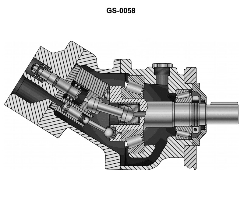
Question: The discharge capacity of the axial piston hydraulic pump, shown in the illustration, is _______________. Illustration GS-0058
A. increased by adding a shorter cylinder block
B. fixed by the pump housing angle
C. decreased by adding a longer cylinder block
D. increased by adding a longer cylinder block
The correct answer is B) the discharge capacity of the axial piston hydraulic pump is fixed by the pump housing angle. The discharge capacity of an axial piston hydraulic pump is determined by the angle of the pump housing, not by the length of the cylinder block. Increasing the cylinder block length (option C) would not affect the discharge capacity, as it is the angle of the swash plate within the pump housing that controls the stroke volume and thus the discharge capacity. Adding a shorter cylinder block (option A) or a longer cylinder block (option D) would not change the fundamental operating principle of the axial piston pump, which is defined by the fixed pump housing angle.
Question 22
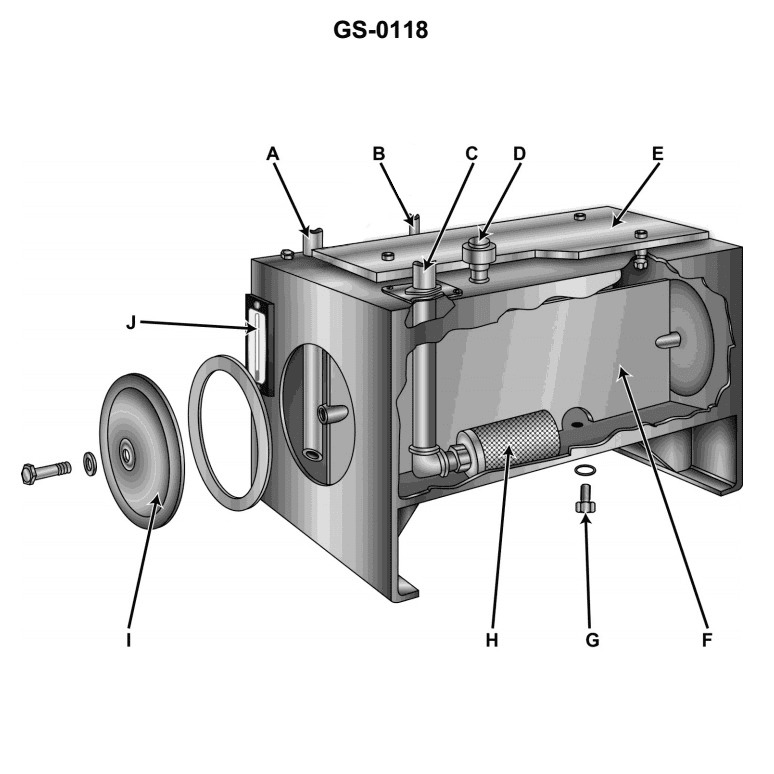
Question: In a hydraulic system using the device illustrated, the high-pressure return is provided by _______________. Illustration GS-0118
A. A
B. B
C. C
D. D
The correct answer is A. In the hydraulic system illustrated in GS-0118, the high-pressure return is provided by the component labeled A. This is because the high-pressure return line carries the pressurized fluid from the hydraulic actuator or mechanism back to the hydraulic reservoir or pump, completing the hydraulic circuit. The other options (B, C, and D) likely represent other components of the hydraulic system, such as the hydraulic pump, fluid reservoir, or control valves, but they do not directly provide the high-pressure return function.
Question 47
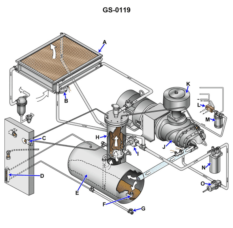
Question: One of the functions of the component labeled "E", shown in the illustration, is to _______________. Illustration GS-0119
A. act solely as a heat exchanger
B. act as a cyclonic pneumatic dehydrator
C. provide storage for compressed cryogenic gases
D. act as a lube oil sump
The correct answer is D) act as a lube oil sump. The lube oil sump, labeled as component "E" in the illustration, is responsible for storing the lubricating oil used by the engine or other mechanical systems. This oil sump provides a reservoir of oil that can be circulated through the engine or other components to reduce friction and wear. The other answer choices are incorrect because: A) A heat exchanger is a different component used to transfer heat, not store lubricating oil. B) A cyclonic pneumatic dehydrator is used to remove moisture from air or gas systems, not for lubricating oil storage. C) Compressed cryogenic gases require specialized storage tanks, not a general lube oil sump.
Question 50
Question: The air compressor shown in the illustration, when used aboard a vessel is typically operated as _______________. Illustration GS-0119
A. a diesel engine air start unit only
B. a constant pressure unit while operating under all load conditions
C. an on-off cycle unit
D. a constant capacity unit
The correct answer is D) a constant capacity unit. The air compressor shown in the illustration GS-0119 is typically operated as a constant capacity unit when used aboard a vessel. This means that the compressor maintains a constant flow rate of air regardless of the load conditions. This ensures a reliable and consistent supply of compressed air for various onboard systems, such as starting engines or operating pneumatic tools. The other answer choices are incorrect because: A) the air compressor is not solely used for diesel engine air start, B) it does not operate at a constant pressure under all load conditions, and C) it does not cycle on and off based on demand.
Question 51
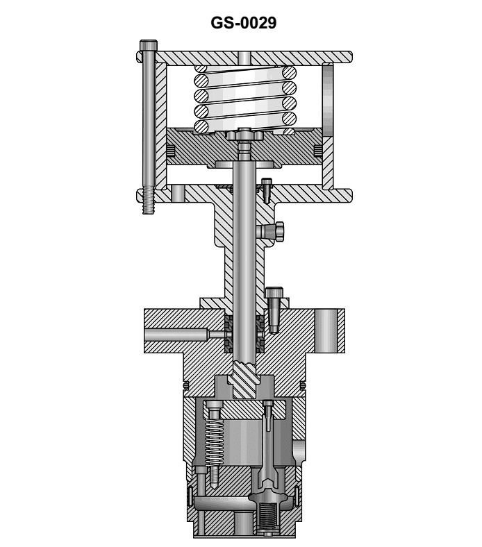
Question: The primary function of the device illustrated is to _______________. Illustration GS-0029
A. remove all but the frictional load of an air compressor at start-up
B. intensify the pressure developed by an air compressor during its normal running operation
C. pre-charge the cylinders of an air compressor prior to the start-up of the unit
D. open the discharge valves during the compressor's operation to supply compressed air
The correct answer is A) remove all but the frictional load of an air compressor at start-up. The primary function of the device illustrated in the image GS-0029 is to reduce the start-up load on the air compressor by removing all but the frictional load. This allows the compressor to start more easily and smoothly, preventing excessive strain on the system. The other answer choices are incorrect because they do not accurately describe the primary function of the device. Option B refers to intensifying pressure during normal operation, while options C and D describe functions related to pre-charging or opening the discharge valves, which are not the main purpose of the illustrated device.
Question 52
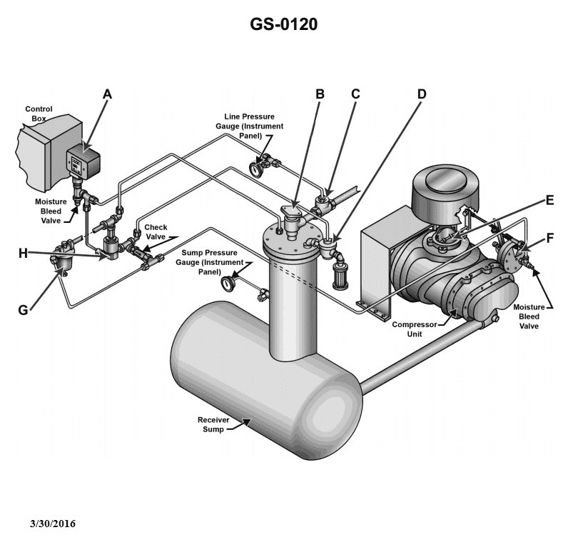
Question: The device shown in the illustration is commonly used to_________________ Illustration GS-0120
A. pump refrigerant
B. generate electricity
C. compress air
D. pump heavy liquids
The correct answer is C) compress air. The device shown in the illustration is commonly used to compress air. This is a critical function on many types of vessels, as compressed air is used for a variety of purposes such as operating pneumatic tools, starting diesel engines, and charging air tanks. The other answer choices are incorrect because the device is not used to pump refrigerant (A), generate electricity (B), or pump heavy liquids (D). Those functions are typically handled by other specialized equipment onboard a vessel.
Question 54
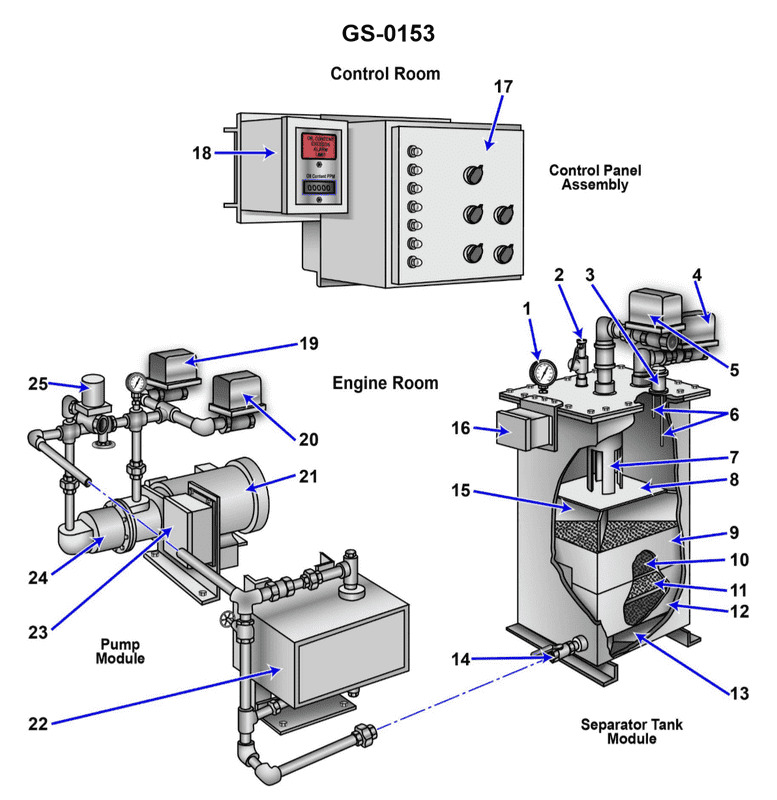
Question: The function of item "7" shown in the illustration is to _______________. Illustration GS-0153
A. direct the flow of the oily-water mixture against the coalescer bed
B. support the tank access panel
C. prevent separated oil from mixing with the incoming bilge water
D. allow the oil accumulated to exit the device, while remaining separated from the liquid
The correct answer is C) prevent separated oil from mixing with the incoming bilge water. The illustration GS-0153 depicts an oily-water separator, a device used on ships to remove oil from bilge water before discharge. Item "7" is likely a valve or fitting that allows the separated oil to exit the device, while preventing the oil from re-mixing with the cleaner bilge water. This ensures that only the oil-free water is discharged, in compliance with environmental regulations for vessel discharges. The other options are incorrect because: A) refers to the coalescer bed, not item 7; B) refers to a tank access panel, not the function of item 7; and D) is similar to the correct answer, but does not specifically mention preventing oil from mixing with incoming bilge water.
Question 55
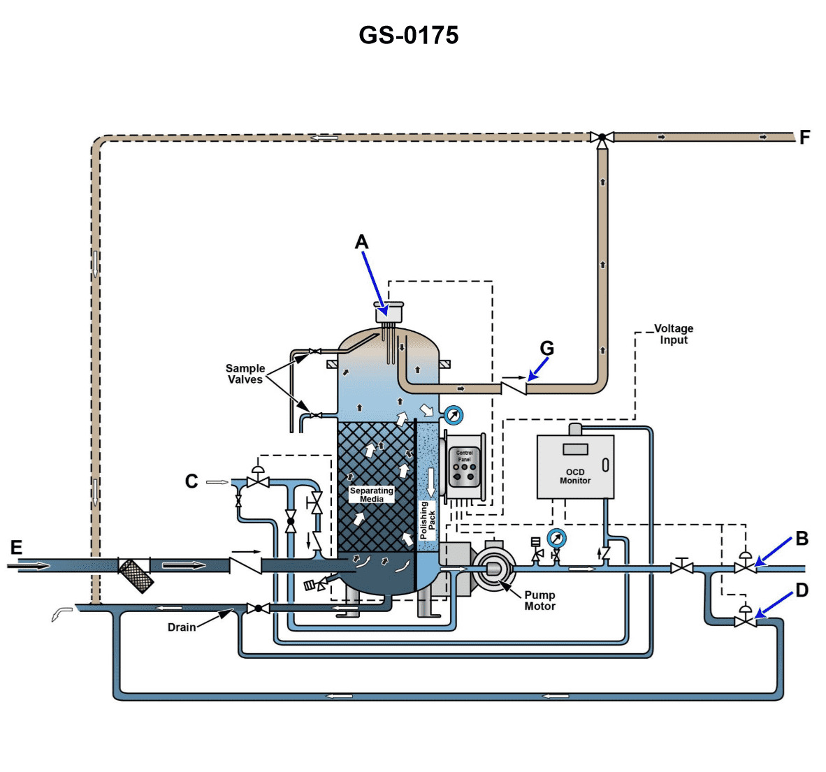
Question: The line labeled "C", as shown in the illustration would be identified as the _______________. Illustration GS-0175
A. oil discharge line
B. clean water flushing line
C. oily bilge water inlet
D. tank drain line
The correct answer is B) clean water flushing line. The line labeled "C" in the illustration GS-0175 would be identified as the clean water flushing line. This line is used to flush out the oily bilge water system, removing any remaining oil or contaminants before discharging the water overboard. The other answer choices are incorrect because: A) The oil discharge line is typically labeled differently and is used to directly discharge oil or oily waste overboard. C) The oily bilge water inlet line would be used to collect the oily bilge water, not flush the system. D) The tank drain line is used to drain liquid from a storage tank, not the bilge water system.
Question 56
Question: Which of the valves listed for the device shown in illustration will be open while the unit is operating in the back flush mode? Illustration GS-0153
A. valve "4"
B. valves "4" and "5"
C. valves "4" and "14"
D. valves "4", "5", and "14"
The correct answer is C) valves "4" and "14". When operating in the back flush mode, valves 4 and 14 need to be open to allow water to flow through the system in the reverse direction for cleaning purposes. Valve 4 allows water to enter the system, while valve 14 provides the exit path for the back flushing flow. The other answer choices are incorrect because valve 5 would typically be closed during back flushing, and having all three valves 4, 5, and 14 open is not the correct configuration for the back flush mode of operation.
Question 68
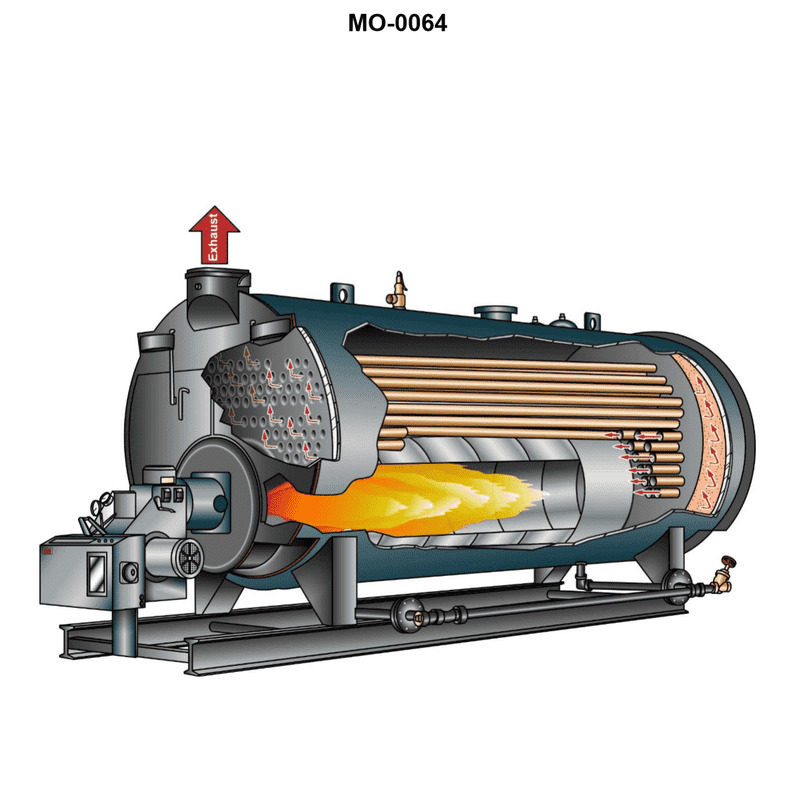
Question: The boiler shown in the illustration would be classed as_______________ Illustration MO-0064
A. forced circulation, coil-type
B. single-pass, fire-tube, scotch marine
C. two-pass, scotch marine
D. two-pass, water-tube
The correct answer is B) single-pass, fire-tube, scotch marine. The illustration MO-0064 depicts a single-pass, fire-tube, scotch marine boiler. This type of boiler is characterized by the combustion gases passing through the fire tubes once before exiting the boiler, which makes it a single-pass design. The fire-tube construction, where the hot gases pass through tubes surrounded by water, is typical of a scotch marine boiler. The other options are incorrect because forced circulation, coil-type boilers (A) have a different design, two-pass, scotch marine boilers (C) have the combustion gases passing through the fire tubes twice, and two-pass, water-tube boilers (D) have a fundamentally different configuration where the water flows through the tubes rather than the combustion gases.
Question 106
Question: Referring to the illustration, note that the solenoid in line "C" is closed. The check valve in line "E" is open. The separator service pump is running. The check valve in line "G" is closed. Valve "B" is closed. Valve "D" is open. What is the operational status of the oily-water separator unit? Illustration GS-0175
A. The oily-water separator is in the bilge water separation processing mode with water discharging back to the bilge water holding tank with an oil content less than 15 ppm.
B. The oily-water separator is in the bilge water separation processing mode with water discharging overboard with an oil content less than 15 ppm.
C. The oily-water separator is in the bilge water separation processing mode with water discharging back to the bilge water holding tank with an oil content greater than 15 ppm.
D. The oily-water separator is in the bilge water separation processing mode with water discharging overboard with an oil content greater than 15 ppm.
The correct answer is C) The oily-water separator is in the bilge water separation processing mode with water discharging back to the bilge water holding tank with an oil content greater than 15 ppm. The reasoning is that with the solenoid in line C closed, the check valve in line E open, and the separator service pump running, the oily-water separator is in the bilge water separation mode. However, with the check valve in line G closed and valve D open, the water is being discharged back to the bilge water holding tank instead of overboard. Since valve B is closed, the oil content of the discharged water is greater than 15 ppm, as it has not been fully separated. The other options are incorrect because they describe scenarios where the water is being discharged overboard (B and D) or with an oil content less than 15 ppm (A and B), which is not the case based on the given information.
Question 123
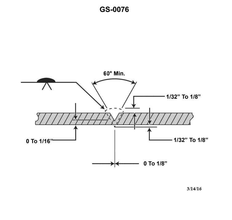
Question: The welding symbol reference line using the inverted "V” indicates _______________. Illustration GS-0076
A. the first pass of the weld is to be back gouged
B. the arrow side of the weld is to be surface finished
C. the opposite side of the weld is to be surface finished
D. a "V" groove weld is to be made
The correct answer is D) a "V" groove weld is to be made. The inverted "V" symbol on the welding reference line indicates that a "V" groove weld is to be made. This is a common welding symbol that specifies the joint preparation required, in this case a "V" shaped groove that the weld metal will fill. The other answer choices are incorrect because they do not accurately describe the meaning of the inverted "V" symbol. Option A refers to back gouging, option B refers to surface finishing on the arrow side, and option C refers to surface finishing on the opposite side - none of these match the meaning of the inverted "V" welding symbol.
Question 126
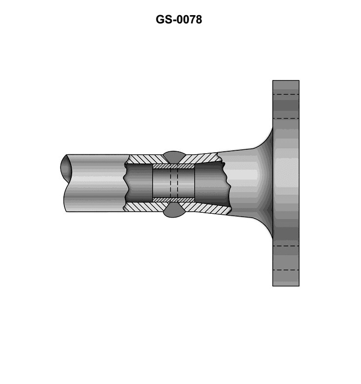
Question: In the illustration, the welded neck flange is attached to the pipe by a _______________. Illustration GS-0078
A. double fillet weld only
B. U-weld over a backing ring
C. plug and slot weld
D. V-weld over a backing ring
The correct answer is D) V-weld over a backing ring. The illustration GS-0078 shows a welded neck flange attached to a pipe, and a V-weld over a backing ring is the appropriate joining method in this case. A V-weld, which creates a V-shaped groove, is a common technique used to weld thick materials like pipe flanges. The backing ring provides support and reinforcement to the weld, ensuring a strong and reliable joint. The other options are incorrect because a double fillet weld (A) would not be suitable for a thick flange attachment, a U-weld over a backing ring (B) is not a standard welding technique, and a plug and slot weld (C) is typically used for different types of joint configurations.
Question 128
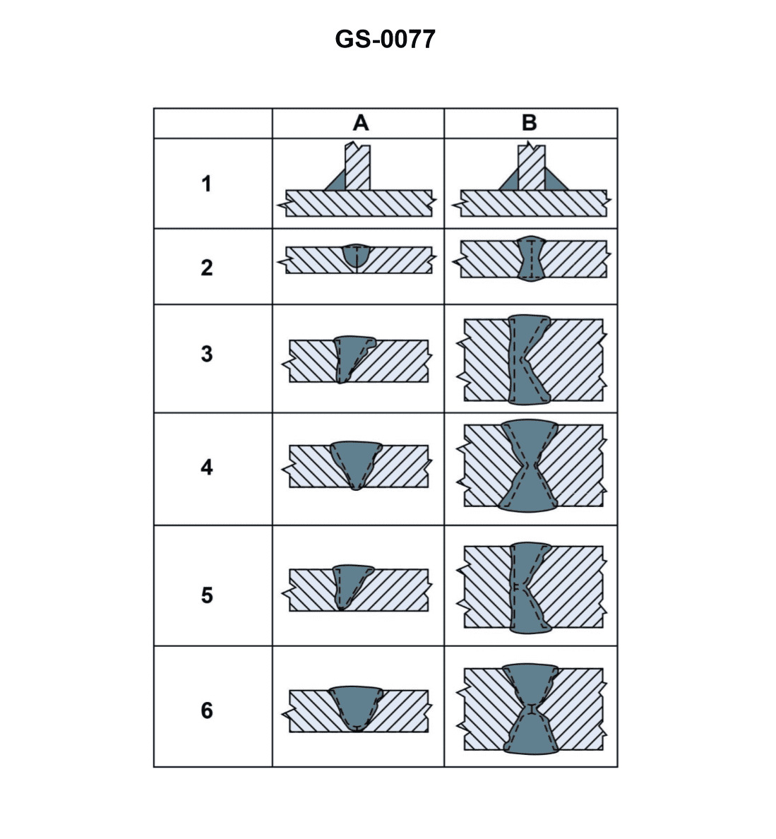
Question: Which illustration correctly depicts a double bevel groove weld? Illustration GS-0077
A. 4A
B. 3B
C. 4B
D. 6B
The correct answer is B) 3B. A double bevel groove weld is a type of welding joint where the edges of the metal pieces to be joined are beveled on both sides, creating a V-shaped groove. The illustration labeled 3B in the GS-0077 set correctly depicts this type of weld joint. The other answer choices do not correctly show a double bevel groove weld. Option A (4A) shows a single bevel groove weld, option C (4B) shows a square groove weld, and option D (6B) shows a J-groove weld, which are all different types of welding joints.
Question 142
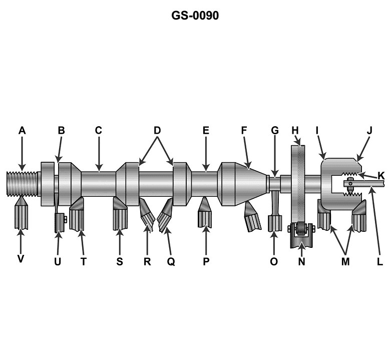
Question: The lathe tool shown as figure "N" in the illustration is commonly known as a/an _______________. Illustration GS-0090
A. curling tool
B. hurling tool
C. furling tool
D. knurling tool
The correct answer is D) knurling tool. A knurling tool is a lathe tool that is used to create a textured pattern or "knurling" on the surface of a workpiece. This is commonly done to provide a better grip on cylindrical parts, such as handles or knobs. The illustration GS-0090 clearly shows a knurling tool, which is the correct identification based on the function and appearance of the tool depicted. The other answer choices are incorrect as they do not accurately describe the type of tool shown in the illustration. A curling, hurling, or furling tool would not be the appropriate identification for the lathe tool depicted.
Question 143
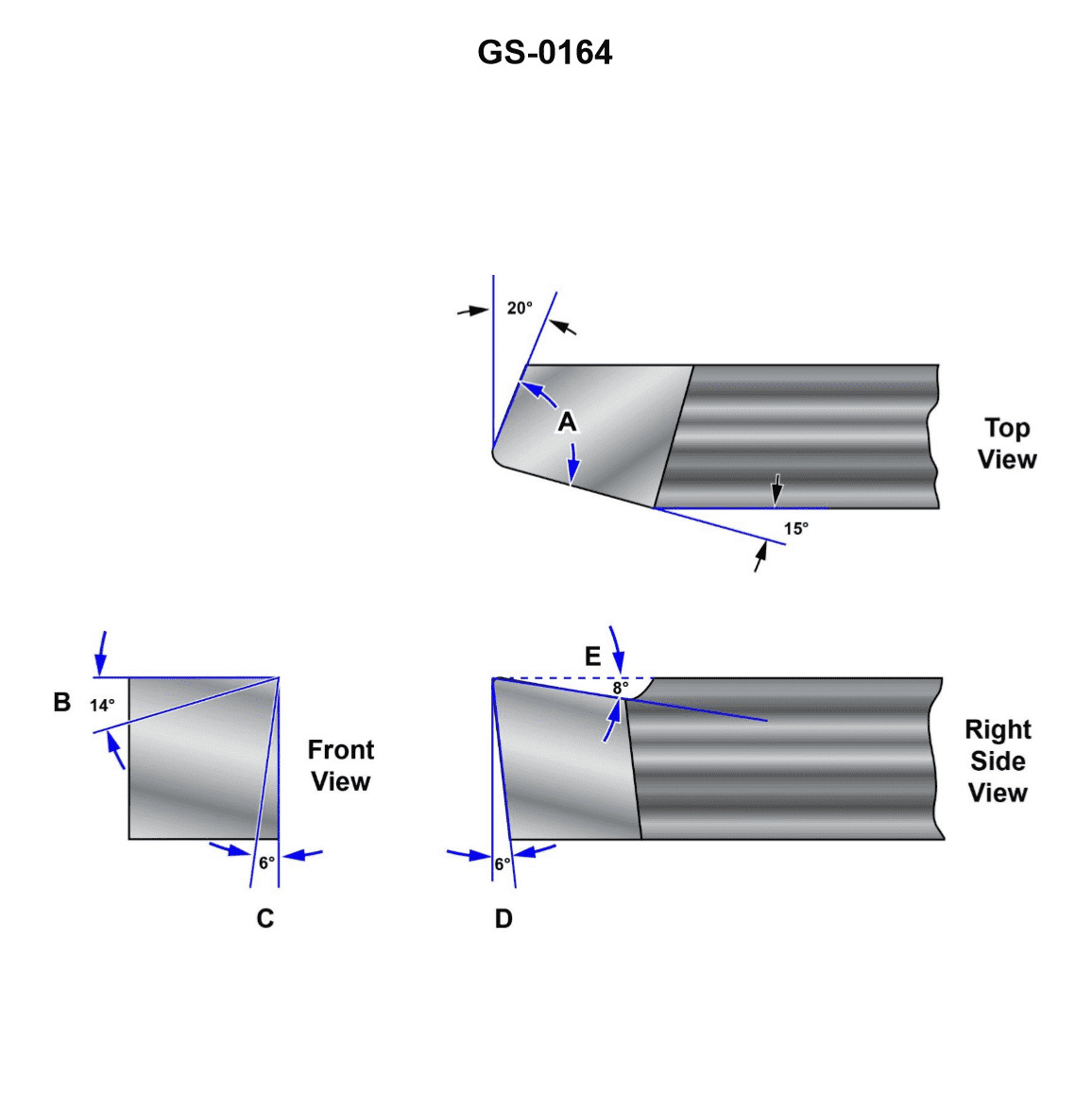
Question: The angle "A" shown on the illustrated lathe tool bit is properly called the . Illustration GS-0164
A. nose angle
B. working relief angle
C. side rake angle
D. side relief angle
The correct answer is A) nose angle. The nose angle is the angle between the tool face and the work surface at the very tip or nose of the lathe tool bit. This angle is important for determining the cutting characteristics of the tool, such as its ability to produce a smooth finish on the workpiece. The other answer choices are not correct because: B) working relief angle refers to the angle behind the cutting edge that provides clearance for the tool to move freely. C) side rake angle refers to the angle of the tool face in the horizontal plane. D) side relief angle refers to the angle behind the cutting edge in the horizontal plane.
Question 144
Question: Which of the illustrated figures represents the use of a right hand roughing tool? Illustration GS-0090
A. Figure P
B. Figure S
C. Figure T
D. Figure V
The correct answer is C) Figure T. The illustration GS-0090 is depicting various tool positions and usages, and Figure T specifically represents the use of a right-hand roughing tool. This is the correct answer based on the standard practices and regulations governing the use of hand tools in the maritime industry. The other answer choices do not depict the use of a right-hand roughing tool, as Figure P shows a parting tool, Figure S depicts a facing tool, and Figure V illustrates the use of a left-hand roughing tool, which is not the same as the right-hand tool described in the question.
Question 145
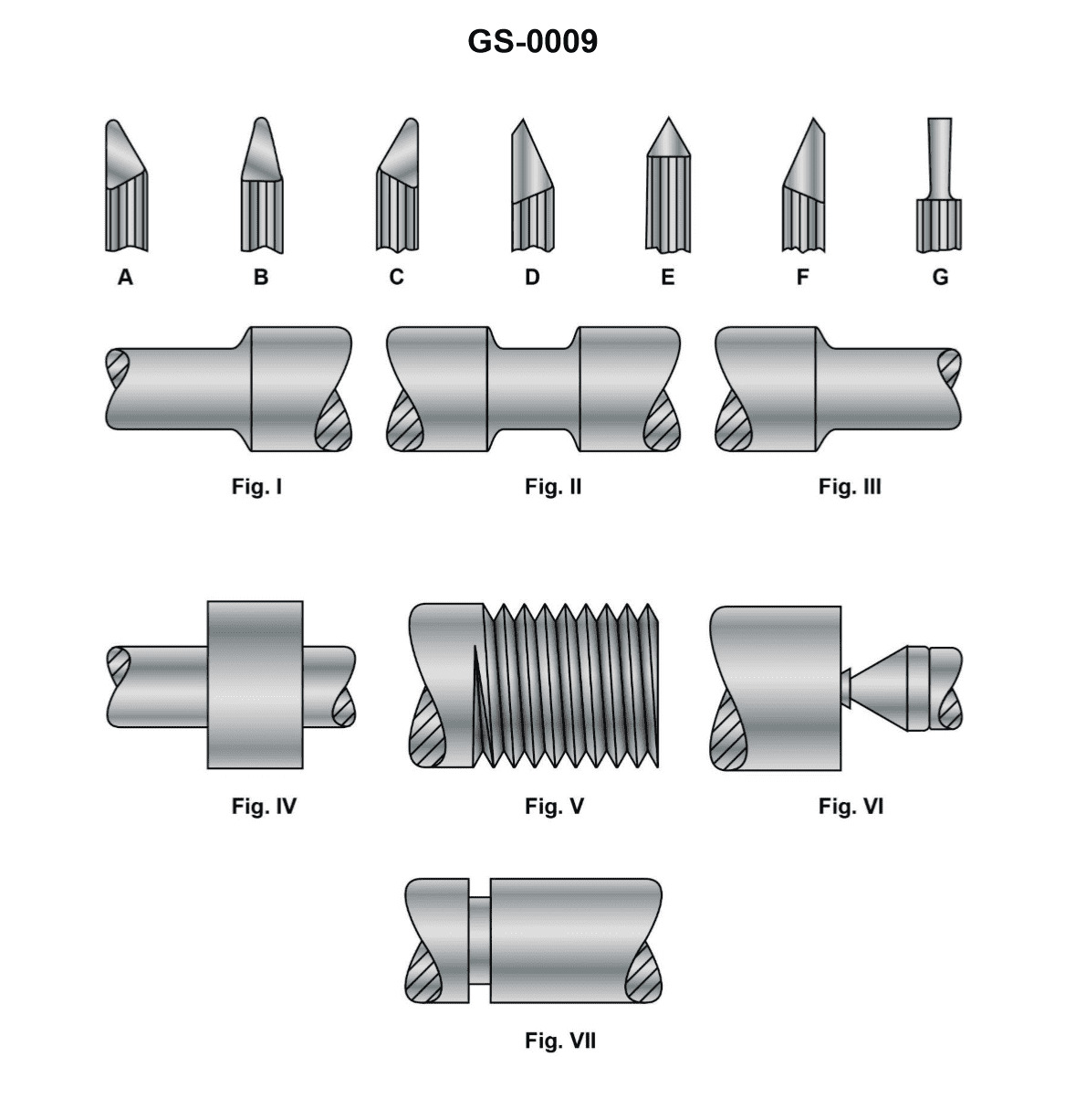
Question: Which of the illustrated lathe tools would be used to produce a smooth finish cut for figure I? Illustration GS-0009
A. A
B. F
C. G
D. D
The correct answer is A. The tool that would be used to produce a smooth finish cut for figure I in illustration GS-0009 is a tool called a cutting tool or finishing tool. This type of tool is designed to create a smooth, high-quality surface finish on a workpiece. The other options, such as a threading tool (F), a grooving tool (G), or a parting tool (D), are not intended for creating a smooth finish and would not be the best choice for this application.
Question 147
Question: The lathe tools shown as figure "M" in the illustration are commonly known as _______________. Illustration GS-0090
A. universal turning tools
B. parting tools
C. form tools
D. curvature cutting tools
The correct answer is C) form tools. Form tools are specifically designed to create a specific shape or profile on the workpiece, such as grooves, fillets, or other complex contours. This matches the illustration GS-0090, which depicts lathe tools used for creating specialized shapes, making form tools the most appropriate answer. The other options are incorrect because: A) universal turning tools are general-purpose lathe tools used for basic turning operations, B) parting tools are used to separate or part off the workpiece, and D) curvature cutting tools is not a commonly used term for lathe tools.
Question 148
Question: The lathe tool shown as figure "U" in the illustration is commonly known as a/an _______________. Illustration GS-0090
A. left cut side-facing tool
B. right side end facing tool
C. cutting-off tool
D. universal turning tool
The correct answer is C) cutting-off tool. The cutting-off tool, also known as a parting tool, is a lathe tool that is used to cut or part off a workpiece from the main material. This tool is designed with a narrow, sharp cutting edge that allows it to cut straight into the workpiece, separating it from the larger material. This is the typical function of the tool shown as figure "U" in the illustration. The other answer choices are not accurate descriptions of this particular lathe tool. A left cut side-facing tool, a right side end facing tool, and a universal turning tool all have different shapes and purposes compared to a cutting-off tool.
Question 153
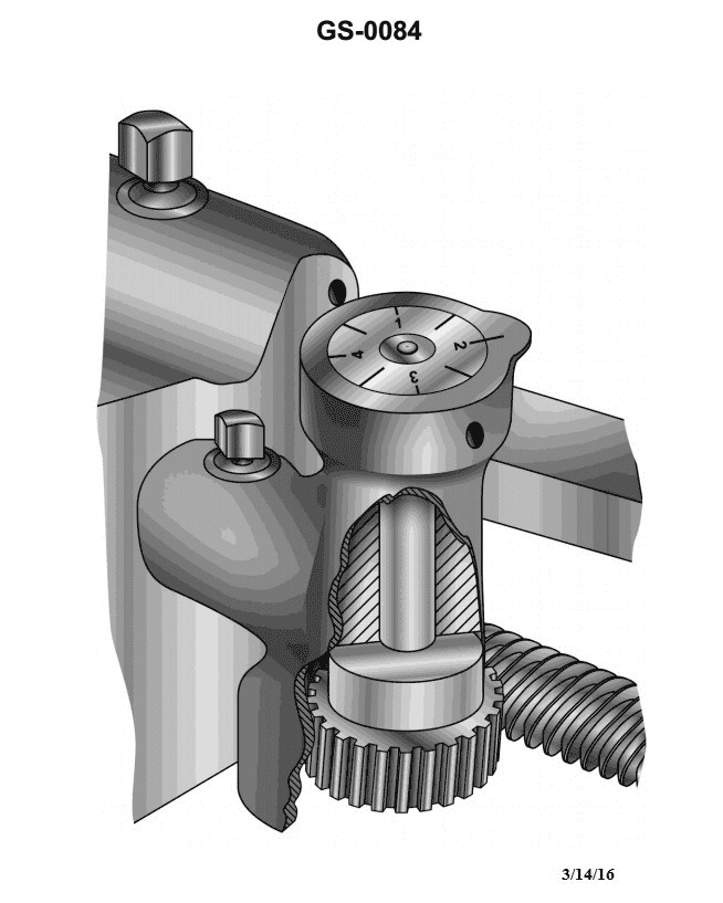
Question: To properly cut even numbered threads using the lathe thread dial indicator shown in the illustration, you should close the lathe split or half-nut on_______________ Illustration GS-0084
A. any line on the dial
B. any unnumbered half line
C. odd numbered lines only
D. even numbered lines only
The correct answer is A) any line on the dial. To properly cut even numbered threads using the lathe thread dial indicator, you should close the lathe split or half-nut on any line on the dial, not just the even numbered lines. This is because the thread dial indicator is used to determine when to engage the half-nut to continue the threading process, and it does not matter whether the line is even or odd numbered. As long as you consistently engage the half-nut on the same line, you will be able to cut even numbered threads correctly. The other options are incorrect because C) closing the half-nut on odd numbered lines only would not allow you to cut even numbered threads, and D) closing the half-nut on even numbered lines only is not necessary to cut even numbered threads.
Question 156
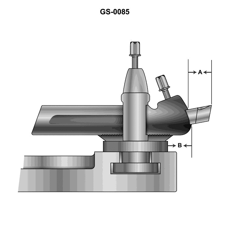
Question: If the distances "A" and/or "B" as shown in the illustration are excessively increased, the tool will _______________. Illustration GS-0085
A. take a deeper cut in the work
B. slip in the tool post
C. chatter
D. take a shallow cut
The correct answer is C) chatter. If the distances "A" and/or "B" as shown in the illustration are excessively increased, the tool will be more susceptible to chatter. Chatter is an undesirable vibration that can occur in machining operations, which can negatively affect the surface finish and dimensional accuracy of the workpiece. Increasing the distances "A" and/or "B" reduces the tool's rigidity, making it more prone to vibration and chatter during the cutting process. The other answer choices are incorrect because they do not accurately describe the effect of excessively increasing the tool's distances "A" and/or "B".
Question 162
Question: To properly cut an odd numbered thread with a lathe using the thread dial indicator illustrated, you should close the lathe split, or half-nut on _______________. Illustration GS-0084
A. any numbered line on the dial
B. even numbered lines only
C. odd numbered lines only
D. any line on the dial
The correct answer is A) any numbered line on the dial. When cutting an odd-numbered thread using a lathe's thread dial indicator, you should close the lathe's split or half-nut on any numbered line on the dial. This is because the thread dial indicator is designed to align the lead screw of the lathe with the workpiece, allowing you to cut the desired thread pitch accurately, regardless of whether the thread is odd or even numbered. The other options are incorrect because B) closing on even-numbered lines only would not work for cutting odd-numbered threads, C) closing on odd-numbered lines only is unnecessary, and D) closing on any line, regardless of numbering, is not the optimal technique for cutting odd-numbered threads.
Question 166
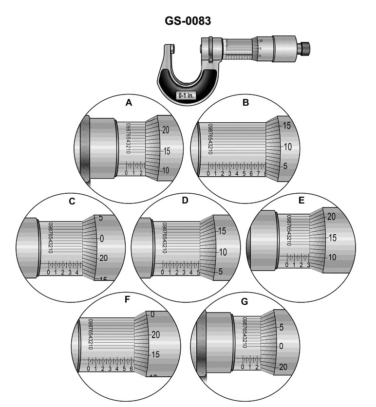
Question: What is the reading of the vernier micrometer caliper scale shown in figure "G" in the illustration? Illustration GS-0083
A. 0.2280 inch
B. 0.2340 inch
C. 0.2470 inch
D. 0.2520 inch
The correct answer is C) 0.2470 inch. The reading of the vernier micrometer caliper scale shown in figure "G" is 0.2470 inch. This can be determined by examining the main scale of the micrometer, which indicates the measurement in increments of 0.025 inch, and the vernier scale, which allows for more precise readings in increments of 0.0005 inch. In the illustration, the main scale is aligned with the 0.245 inch mark, and the vernier scale is aligned with the 0.0020 inch mark, which combined gives a reading of 0.2470 inch. The other answer choices are incorrect because they do not accurately reflect the reading shown in the illustration.
Question 170
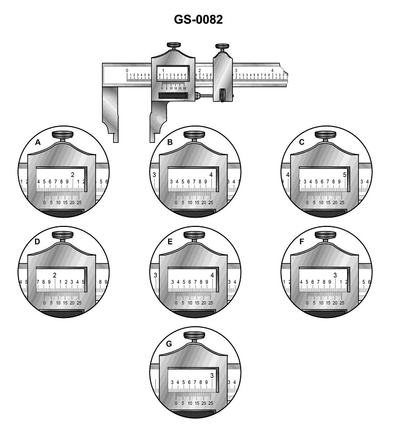
Question: The reading on the vernier caliper scale shown in figure "G" in the illustration is _______________. Illustration GS-0082
A. 2.308 inches
B. 2.368 inches
C. 2.380 inches
D. 2.965 inches
The correct answer is B) 2.368 inches. The reasoning behind this is that a vernier caliper, which is a precision measuring instrument, allows for measurements to be taken with a high degree of accuracy. The illustration shows the vernier scale, and by aligning the markings on the vernier scale with the main scale, the reading can be determined to be 2.368 inches. The other options are incorrect because they do not accurately reflect the reading shown in the illustration. Option A (2.308 inches) and Option C (2.380 inches) are off by the precision of the vernier scale, while Option D (2.965 inches) is significantly different from the correct reading.
Question 173
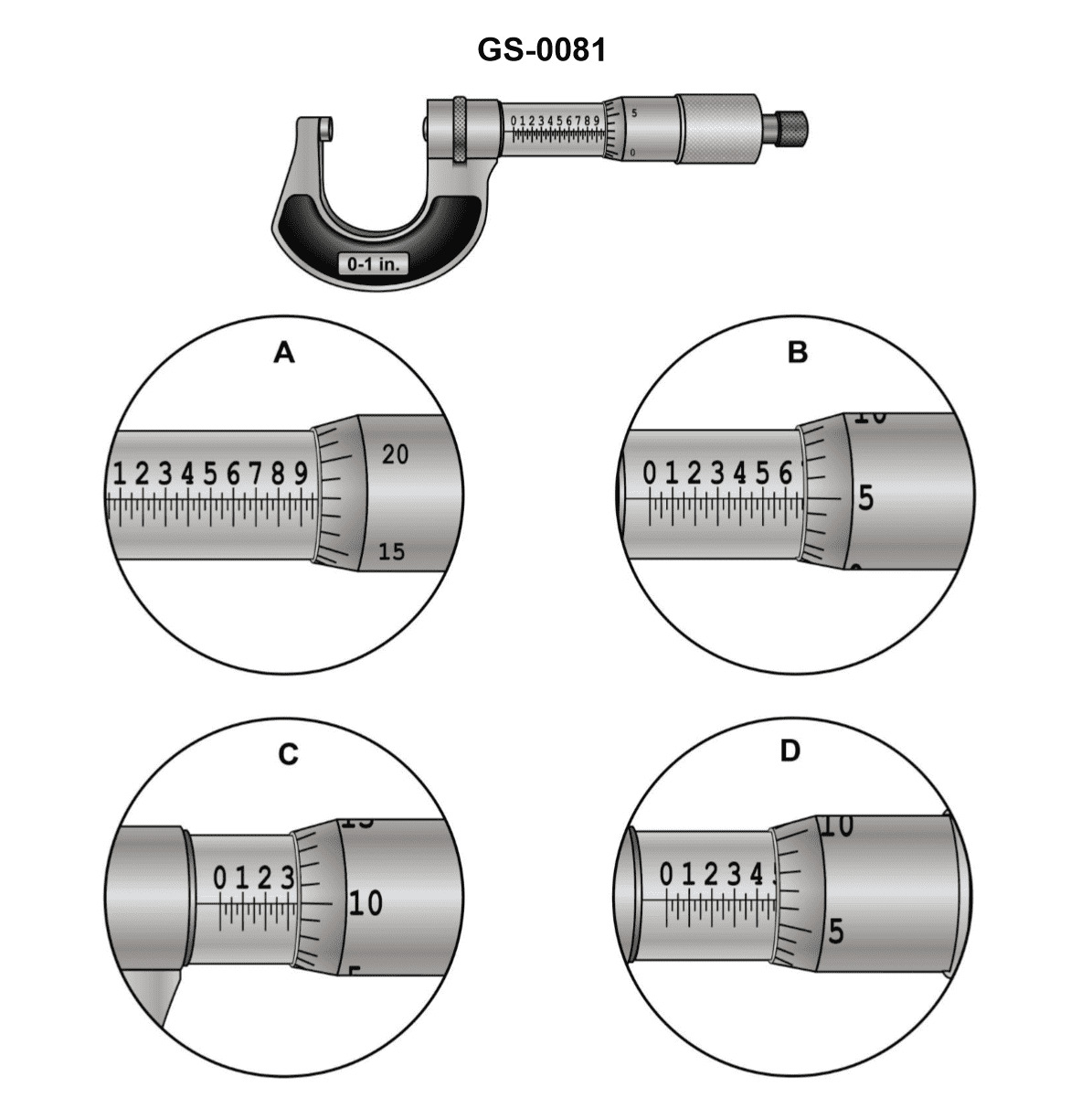
Question: The reading on the micrometer scale shown in figure "D" in the illustration is _______________. Illustration GS-0081
A. 0.4710 inch
B. 0.4715 inch
C. 0.4810 inch
D. 0.4815 inch
The correct answer is D) 0.4815 inch. The reading on the micrometer scale shown in figure "D" of the illustration is 0.4815 inch. This can be determined by closely examining the position of the thimble-shaped sleeve relative to the graduated scale on the micrometer barrel. The thimble has moved past the 0.48 inch mark, and the graduation line on the thimble aligns with the 0.0015 inch mark on the scale, indicating a total reading of 0.4815 inch. The other answer choices are incorrect because they do not accurately represent the measurement shown in the illustration.
Question 228
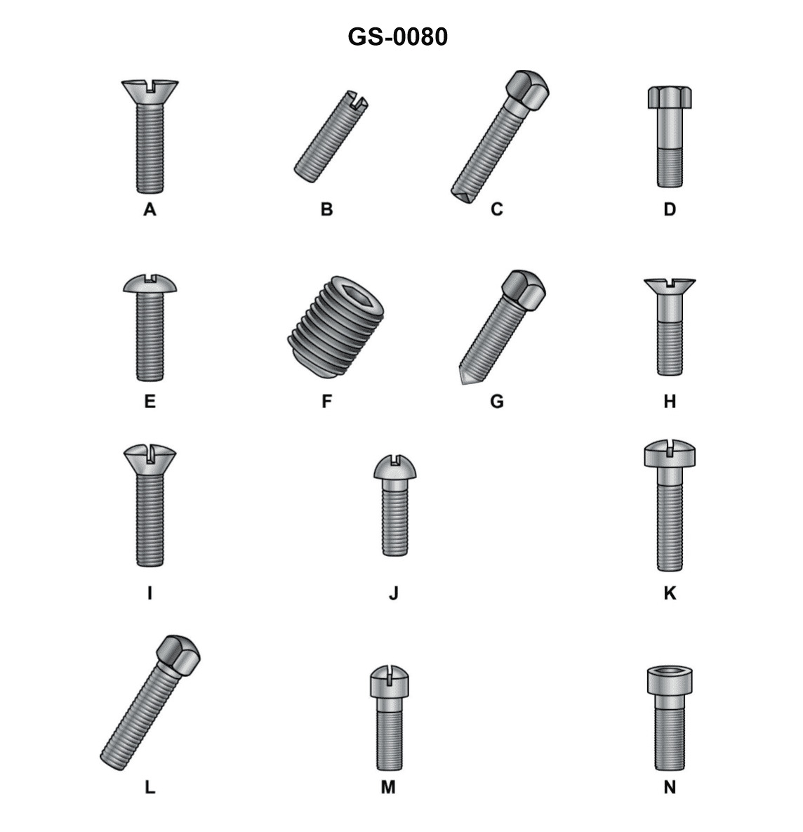
Question: The device "F" shown in the illustration is best used to_______________ Illustration GS-0080
A. secure tapered pins in position
B. fasten pump casing flanges together
C. assist in securing a coupling half to its shaft
D. bolt motor frames to bedplates
The correct answer is C) assist in securing a coupling half to its shaft. The device "F" shown in the illustration is likely a type of coupling hub or coupling assembly, which is used to connect a rotating shaft to another component, such as a pump or motor. The purpose of a coupling is to transmit rotational torque from one shaft to another, and the coupling hub is the part that attaches directly to the shaft. The other answer choices are incorrect because they do not accurately describe the function of the device "F" as depicted in the illustration. Securing tapered pins, fastening pump casing flanges, and bolting motor frames are all different mechanical tasks that would not be the primary purpose of the coupling hub shown.
Question 230
Question: The letters 'NC' in '1/4-20 NC' indicates the bolt is _______________.
A. threaded with national coarse threads
B. made of nickel-cadmium metal
C. made of non-corrosive metal
D. not clad with any coating
The correct answer is A) threaded with national coarse threads. The 'NC' in '1/4-20 NC' refers to the thread designation 'National Coarse', which is a standard thread pattern commonly used in the United States. This thread pattern has a larger thread pitch compared to the 'National Fine' (NF) thread, making it suitable for applications where greater strength or faster assembly is required. The other answer choices are incorrect because they do not accurately represent the meaning of the 'NC' designation in the bolt specification. Option B is incorrect as it refers to the material composition, while options C and D are not directly related to the thread type indicated by 'NC'.
Question 231
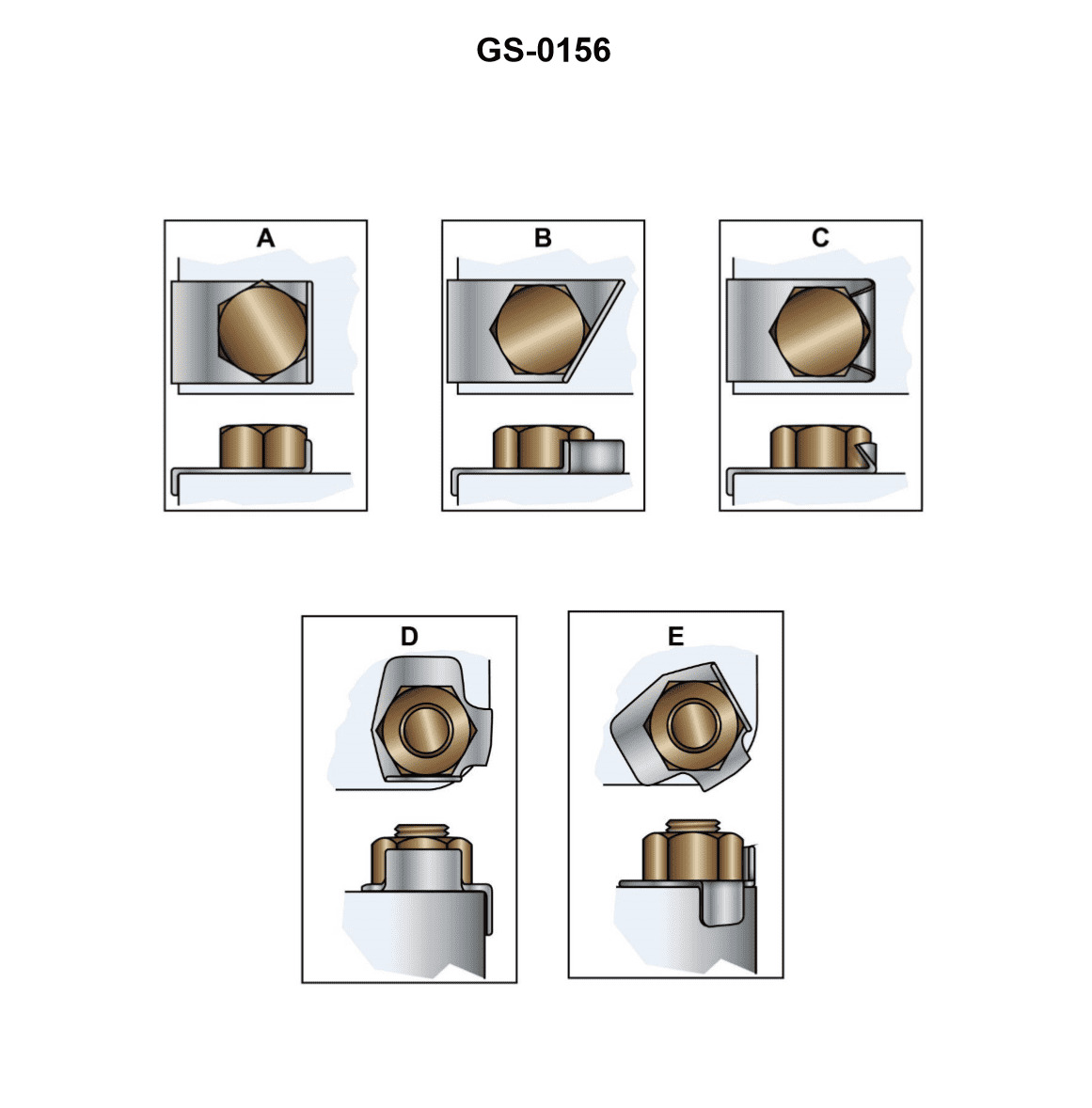
Question: What is the primary function of the devices shown in the illustration? Illustration GS-0156
A. The transit washers transmit the rotary motion of the cap screw to the actuating assembly.
B. The locking plates are used to prevent the fastening devices from vibrating loose.
C. The grounding straps help prevent electrolysis by improving the conductivity between the components.
D. These abrasion resistors prevent damage to the surface around the bolt holes when tightening the bolts.
The correct answer is B) The locking plates are used to prevent the fastening devices from vibrating loose. The primary function of the locking plates shown in the illustration is to prevent the fastening devices, such as bolts or screws, from becoming loose due to vibration. This is an important safety consideration for equipment used on ships and boats, where vibration can be a common issue. The locking plates help maintain the integrity of the connections and prevent potential failures or hazards that could arise from loosened fasteners. The other answer choices are incorrect because they do not accurately describe the purpose of the locking plates in the illustration. The transit washers, grounding straps, and abrasion resistors serve different functions that are not relevant to the primary purpose of the locking plates shown.
Question 232
Question: The locking plates shown in the illustration are used in many marine applications. Which figure indicates the improper method for using these devices? Illustration GS-0156
A. "A"
B. "B"
C. "C"
D. "D"
The correct answer is C. The illustration GS-0156 shows different methods for using locking plates. Option C indicates the improper method, as the locking plate is not properly secured and could potentially come loose, posing a safety hazard. The other options show the locking plates being used in a secure and appropriate manner, in accordance with marine industry standards and best practices.
Question 234
Question: Which of the figures illustrated would be LEAST desirable for use as a set screw? Illustration GS-0080
A. figure A
B. figure F
C. figure G
D. figure L
The correct answer is A) figure A. Figure A represents a headless screw, which would be the least desirable for use as a set screw. Set screws are used to secure one object to another, and they require a head or some other feature that can be easily grasped to tighten or loosen the screw. A headless screw would be difficult to grip and adjust, making it unsuitable for use as a set screw. The other options, figures F, G, and L, all have features such as a head or a knurled surface that would make them more suitable for use as set screws compared to the headless design of figure A.
Question 236
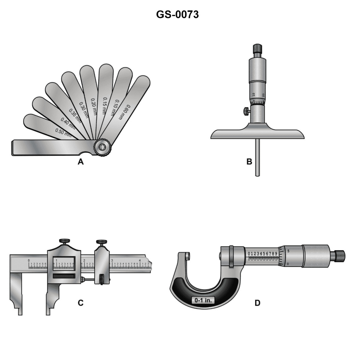
Question: Which of the devices shown in the illustration is designed for both inside and outside measurements? Illustration GS-0073
A. A
B. B
C. C
D. D
The correct answer is C. The device labeled C in the illustration GS-0073 is designed for both inside and outside measurements. This type of device, known as a caliper, is a common tool used in various industries, including the maritime field, to measure the dimensions of objects both internally and externally. The other options, A, B, and D, are not designed for both inside and outside measurements. They may have specific purposes, such as depth measurements or other specialized applications, but they do not serve the dual function of the caliper represented by option C.
Question 241
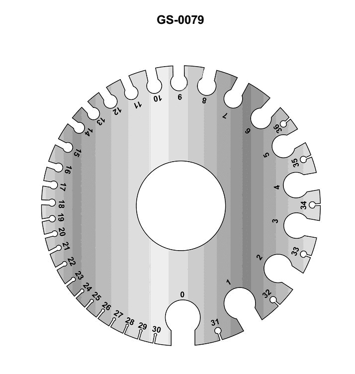
Question: The purpose of the instrument illustrated is to _______________. Illustration GS-0079
A. gage resistors
B. strip insulation from wire
C. measure wire diameter
D. measure insulation thickness
The correct answer is C) measure wire diameter. The illustration GS-0079 appears to depict a micrometer, which is a precision instrument used to measure the diameter or thickness of small objects, such as wire. Micrometers are a common tool used by mariners and engineers to accurately measure the dimensions of various components, including wiring used on vessels. The other answer choices are incorrect because they do not accurately describe the primary function of a micrometer. Gaging resistors, stripping insulation, and measuring insulation thickness are not the intended purposes of this instrument.
Question 245
Question: Which of the devices shown in the illustration should be used with a bridge gage? Illustration GS-0073
A. A
B. B
C. C
D. D
The correct answer is A. The device shown in option A is a bridge gage, which is used to measure the clearance under a bridge or overhead obstruction. This is the appropriate device to use in conjunction with a bridge gage, as it allows the operator to precisely determine the available vertical clearance. The other options, B, C, and D, are not appropriate for use with a bridge gage, as they serve different purposes, such as measuring depths, distances, or angles, rather than vertical clearance.
Question 254
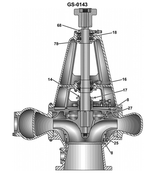
Question: The shaft sleeve for the pump illustrated is identified by the item numbered as _______________. Illustration GS-0143
A. 14
B. 17
C. 27
D. 68
The correct answer is A) 14. The shaft sleeve for the pump illustrated in the GS-0143 diagram is identified by the item numbered as 14. This can be determined by closely examining the diagram and identifying the component labeled with the number 14, which corresponds to the shaft sleeve for the pump. The other answer choices are incorrect because they do not correctly identify the item number associated with the shaft sleeve in the provided illustration. Option B) 17, C) 27, and D) 68 are all incorrect as they do not match the actual item number shown in the diagram.
Question 285
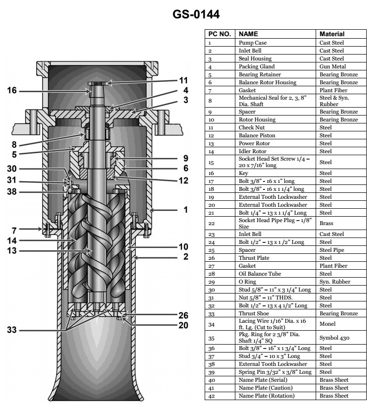
Question: What type of pump is shown in the illustration? Illustration GS-0144
A. Double screw rotary pump
B. Deep well centrifugal pump
C. Simplex reciprocating pump
D. Triple screw rotary pump
The correct answer is D) Triple screw rotary pump. The illustration GS-0144 depicts a triple screw rotary pump, which is a positive displacement pump commonly used on vessels for various applications such as fuel transfer, ballast, and firefighting. The three screw-like rotors within the pump housing create a consistent flow of liquid when the pump is operated, making it well-suited for marine applications. The other answer choices are incorrect because a double screw rotary pump has two rotors, a deep well centrifugal pump uses a different impeller-based mechanism, and a simplex reciprocating pump operates using a piston rather than rotating screws.
Question 290
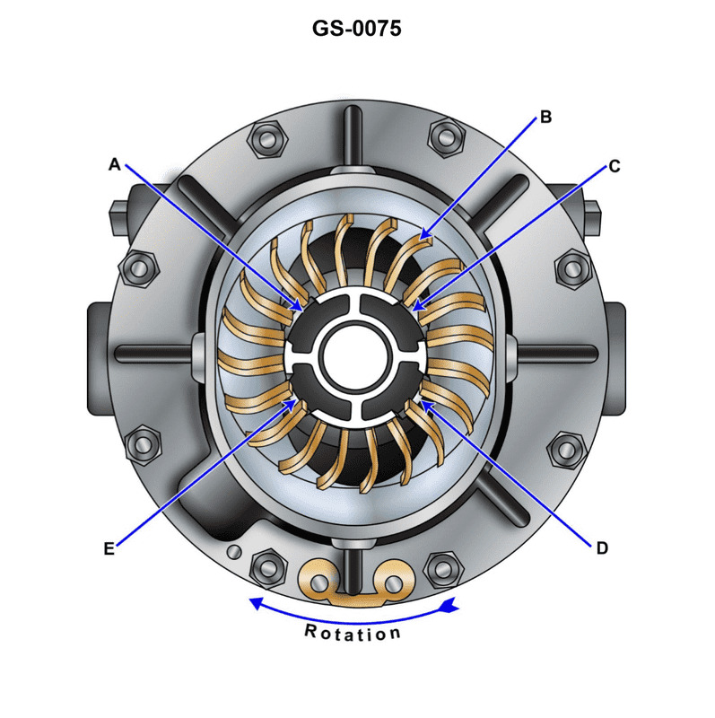
Question: The function of the section labeled "C" in the device illustrated is to provide a/an _______________. Illustration GS-0075
A. area for pump packing
B. passage for sealing liquid to enter the pump
C. bearing surface for the rotor shaft
D. passage for gas to be discharged
The correct answer is D) passage for gas to be discharged. The section labeled "C" in the illustration GS-0075 functions as a passage for gas to be discharged from the device. This is because the primary purpose of this type of device is to pump or compress gas, and the section labeled "C" provides an opening or channel for the gas to exit the pump or compressor after being pressurized. The other answer choices are incorrect because they do not accurately describe the function of this specific section of the device. Options A and B are more applicable to liquid pumps, while option C describes a bearing surface, which is not the primary function of the section labeled "C" in this gas-handling device.
Question 307
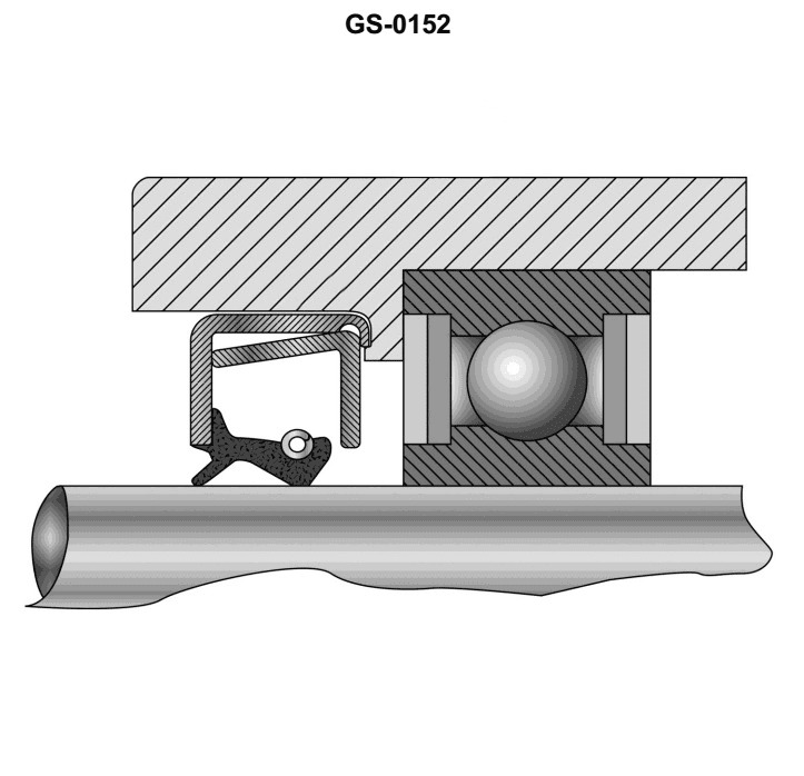
Question: Spring reinforced oil seals are generally installed with the tail or lip of the seal facing _______________. Illustration GS-0152
A. away from the oil pressure being sealed
B. away from the bearing housing recess
C. toward the bearing preload washer
D. toward the oil pressure being sealed
The correct answer is D) toward the oil pressure being sealed. The reason this is the correct answer is that spring-reinforced oil seals are designed to have the lip or tail of the seal facing the direction of the oil pressure being sealed. This orientation helps to ensure a tight seal and prevent oil leakage. The lip or tail of the seal is the flexible part that makes contact with the shaft or surface being sealed, and it needs to face the direction of the oil pressure to effectively contain the oil. The other answer choices are incorrect because they do not align with the proper installation orientation of a spring-reinforced oil seal. Option A would allow oil to potentially leak past the seal, while options B and C would not provide the necessary sealing pressure against the oil flow.
Question 309
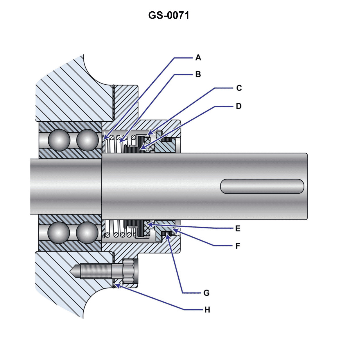
Question: Which of the devices listed is used to maintain a snug interface between the rotating and stationary seal members shown in the illustration? Illustration GS-0071
A. notch and keyway
B. bellows
C. spring
D. seal retaining ring
The correct answer is C) spring. The spring is used to maintain a snug interface between the rotating and stationary seal members shown in the illustration. The spring applies constant pressure to keep the seal components tightly fitted together, preventing leaks and maintaining the proper seal. The other options are incorrect because: A) a notch and keyway are used to align and secure components, not to maintain a seal; B) a bellows is a flexible component that can expand and contract, not a mechanism to maintain a seal; and D) a seal retaining ring is used to hold the seal in place, not to create the snug interface between the seal members.
Question 321
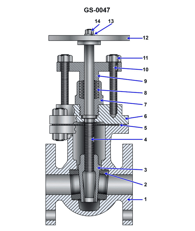
Question: Which of the following statements is true concerning the valve shown in the illustration? Illustration GS-0047
A. The valve only requires one turn of the hand wheel to fully open.
B. The valve seats cannot be replaced or repaired.
C. The valve is normally used to throttle the flow of liquid.
D. The valve is a non-rising stem design.
The correct answer is D) The valve is a non-rising stem design. The non-rising stem design is a common feature of valves used in marine applications, as it helps prevent the valve stem from becoming stuck or seized in the open or closed position. In this type of valve, the stem does not move up and down as the valve is opened or closed, but instead rotates to open and close the valve. This makes it a more reliable and durable option for use in the marine environment. The other answer choices are incorrect: A) is false, as most valves require multiple turns of the handwheel to fully open or close; B) is false, as valve seats can typically be replaced or repaired; and C) is not necessarily true, as this type of valve may be used for a variety of flow control applications, not just throttling.
Question 323
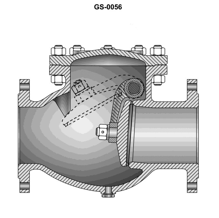
Question: The illustrated valve is known as a _______________. Illustration GS-0056
A. lift gate valve
B. butterfly lift valve
C. swing check valve
D. swing globe valve
The correct answer is C) swing check valve. A swing check valve is a type of check valve that uses a hinged flap to allow flow in one direction but prevent backflow. The flap is connected to a hinge that allows it to swing open when flow is in the desired direction, but swing shut to block reverse flow. This is the type of valve depicted in the illustration GS-0056. The other answer choices are incorrect because they do not accurately describe the type of valve shown. A lift gate valve, butterfly lift valve, and swing globe valve have different internal mechanisms and operating principles that do not match the illustration.
Question 324
Question: What type of valve is shown in the illustration? Illustration GS-0047
A. Check valve
B. Butterfly valve
C. Globe valve
D. Gate valve
The correct answer is D) Gate valve. A gate valve is a type of valve that uses a movable gate or wedge to control the flow of fluid. The illustration GS-0047 depicts the cross-section of a gate valve, which matches the physical characteristics and operation of this type of valve. The other answer choices are incorrect because: A) A check valve is designed to allow flow in only one direction, B) A butterfly valve uses a rotary disc to control flow, and C) A globe valve uses a rounded or spherical disc to restrict flow, rather than the linear motion of a gate valve.
Question 344
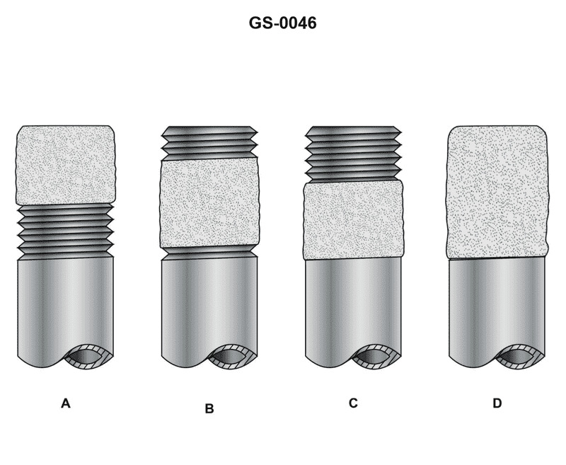
Question: Which of the illustrations depicts the correct procedure for applying pipe dope? Illustration GS-0046
A. A
B. B
C. C
D. D
The correct answer is B. The illustration that depicts the correct procedure for applying pipe dope is option B. Proper application of pipe dope involves applying a thin, even coating to the threads of the pipe fitting, which is shown in illustration B. The other options either show excessive application of pipe dope (A and D) or do not adequately cover the pipe threads (C), which could lead to improper sealing and potential leaks.
Question 354
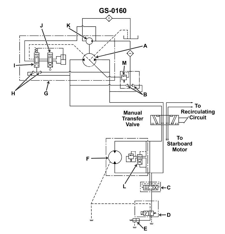
Question: In the hydraulic anchor windlass system illustrated, pressure relief of the main pressure piping is provided by _______________. Illustration GS-0160
A. D
B. E
C. L
D. M
The correct answer is C) L. The illustration GS-0160 depicts a hydraulic anchor windlass system, and the question asks about the pressure relief of the main pressure piping in this system. The correct answer is C) L, which indicates that the pressure relief is provided by a pressure relief valve. Pressure relief valves are a crucial component in hydraulic systems to prevent damage from excessive pressure buildup. They are designed to open and release pressure when the system pressure exceeds a predetermined limit, protecting the components and ensuring safe operation of the hydraulic anchor windlass system. The other answer choices, A) D, B) E, and D) M, do not represent the correct pressure relief mechanism in this specific hydraulic anchor windlass system illustrated.
Question 360
Question: The hydraulic pump which would be mounted on the unit shown in the illustration, may begin to cavitate if _______________. Illustration GS-0118
A. "A" is allowed to remain open
B. "B" is over-tightened
C. "H" were to be removed and the system operated for thirty minutes without it being replaced
D. "D" is not kept clean
The correct answer is D) "D" is not kept clean. The hydraulic pump can begin to cavitate if the filter or strainer ("D" in the illustration) is not kept clean. Cavitation occurs when the pump is not able to draw in enough fluid, often due to a clogged or dirty filter, which can cause the pump to lose efficiency and potentially become damaged. Keeping the filter or strainer clean is crucial to maintain proper hydraulic system operation and prevent cavitation. The other answer options are incorrect because they do not directly relate to the causes of cavitation in the hydraulic pump. "A" being open or "B" being over-tightened would not necessarily lead to cavitation, and "C" removing "H" would not directly impact the pump's ability to draw in fluid.
Question 363
Question: In the hydraulic anchor windlass system illustrated, if the power to the electric motor is on, but the wildcat turns slowly or not at all, even without a load being applied, and nearly normal pressure is indicated on the high side of the system, the probable cause is the _______________. Illustration GS-0160
A. manual transfer valve is in the wrong position for the main pump being operated
B. relief valve "L" is not closing
C. replenishing pump coupling is broken
D. pressure from "E" has failed to bleed off when "J" is placed in the operating position
The correct answer is B) relief valve "L" is not closing. If the wildcat is turning slowly or not at all, even without a load, and the pressure on the high side of the system is nearly normal, it indicates that the hydraulic system is not functioning properly. The likely cause is that the relief valve "L" is not closing, which allows the hydraulic fluid to bypass the windlass and prevent it from turning at the expected speed. The other options are incorrect because: A) the manual transfer valve position is not relevant if the system is not functioning properly; C) a broken replenishing pump coupling would not cause the specific symptoms described; and D) the pressure from "E" bleeding off when "J" is in the operating position is not the issue here.
Question 364
Question: In the hydraulic anchor windlass system illustrated, if the power to the electric motor is on, but the wildcat does not turn, the pressure developed on either side of the system increases to half of the normal operating pressure regardless of the direction of movement in which the servo control is placed, the probable cause is the _______________. Illustration GS-0160
A. replenishing pump coupling is broken
B. relief valve is not opening
C. manual transfer valve is in the wrong position for the main pump being operated
D. spring set point for "I" is too high
The correct answer is C) the manual transfer valve is in the wrong position for the main pump being operated. In a hydraulic anchor windlass system, if the power to the electric motor is on but the wildcat does not turn, and the pressure on both sides of the system increases to half of the normal operating pressure regardless of the direction of movement, it indicates an issue with the hydraulic system rather than the electric motor. The most likely cause in this scenario is that the manual transfer valve is not in the correct position for the main pump being operated. This would prevent the hydraulic fluid from flowing properly through the system, resulting in the increased pressure on both sides without the windlass turning. The other options are incorrect because they do not address the specific symptoms described in the question. A broken replenishing pump coupling would not cause the pressure to increase, the relief valve not opening would lead to full system pressure, and an incorrect spring set point for the pressure control valve would not affect the directional control.
Question 365
Question: In the hydraulic anchor windlass system illustrated, the main pressure relief valve opens as the load increases its strain on the system. The probable cause is the _______________. Illustration GS-0160
A. manual transfer valve is in the wrong position for the main pump being operated
B. replenishing pump discharge check valves are continuously open
C. spring set point "I" is set too high for normal loads
D. relief valve control shuttle has shifted to the wrong position during windlass operation
The correct answer is A) the manual transfer valve is in the wrong position for the main pump being operated. In a hydraulic anchor windlass system, the main pressure relief valve opens as the load increases its strain on the system. This is likely due to the manual transfer valve being in the wrong position for the main pump being operated. When the transfer valve is not aligned correctly, it can restrict the flow of hydraulic fluid, causing the pressure to build up and triggering the relief valve to open. The other options are incorrect because they do not directly explain the probable cause of the relief valve opening. The replenishing pump discharge check valves being continuously open (B), the relief valve control shuttle shifting to the wrong position (D), or the spring set point being set too high (C) may contribute to the problem, but they are not the primary cause in this scenario.