Pass Your Coast Guard Licensing Exams!
Study offline, track your progress, and simulate real exams with the Coast Guard Exams app
Gas Turbine - 1st Asst/Chief
29 images
Question 3
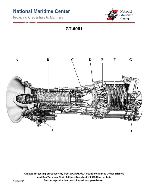
Question: On the gas turbine shown in the illustration, which of the following best describes the main principle of operation of the component contained within the area labeled "C"? Illustration GT-0001
A. Bernoulli's Law of Divergency
B. Newton's Law of Motion
C. Combustion at a constant pressure
D. Otto Cycle
The correct answer is C) Combustion at a constant pressure. In a gas turbine engine, the component labeled "C" is likely the combustion chamber or combustor. The main principle of operation of the combustor is combustion at a constant pressure, which is a key feature of the Brayton cycle that underlies the working of a gas turbine. The other options are incorrect because: A) Bernoulli's principle is not directly relevant to the combustion process, B) Newton's laws describe the motion of objects, not the thermodynamic principles of the combustion chamber, and D) the Otto cycle is applicable to internal combustion engines, not gas turbines.
Question 11
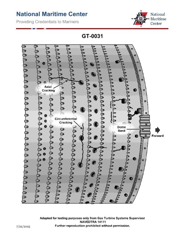
Question: Which of the following statements about the intercooled-recuperated gas turbine cycle is true? Illustration GT-0031
A. Intercooler serves to increase the required high-pressure compressor power, while the recuperator utilizes waste heat form the exhaust to increase turbine inlet temperature.
B. Intercooler serves to increase the required high-pressure compressor power, while the recuperator utilizes waste heat form the exhaust to decrease turbine inlet temperature.
C. Intercooler serves to reduce the required high-pressure compressor power, while the recuperator utilizes waste heat form the exhaust to decrease turbine inlet temperature.
D. Intercooler serves to reduce the required high-pressure compressor power, while the recuperator utilizes waste heat form the exhaust to decrease required fuel to achieve turbine inlet temperature.
The correct answer is D. The intercooled-recuperated gas turbine cycle utilizes an intercooler to reduce the required high-pressure compressor power by cooling the air between the low-pressure and high-pressure compressors. This reduced compressor power requirement leads to a decrease in the amount of fuel required to achieve the desired turbine inlet temperature. The recuperator then utilizes the waste heat from the turbine exhaust to preheat the compressed air entering the combustor, further reducing the required fuel input. The other answer choices incorrectly describe the roles of the intercooler and recuperator in this cycle.
Question 14
Question: What type of gas turbine cycle configuration is shown in the illustration? Illustration GT-0031
A. Recuperative type.
B. Simple type.
C. Intercooled type.
D. Intercooled-recuperated type.
The correct answer is D) Intercooled-recuperated type. This is the correct answer because the illustration GT-0031 depicts a gas turbine cycle configuration that includes both an intercooler and a recuperator. The intercooler lowers the temperature of the compressed air before it enters the combustion chamber, while the recuperator uses the exhaust heat to preheat the air entering the combustion chamber. This combination of an intercooler and a recuperator is characteristic of an intercooled-recuperated type gas turbine cycle. The other options are incorrect because a simple gas turbine cycle lacks both an intercooler and a recuperator (option B), a recuperative cycle has only a recuperator but no intercooler (option A), and an intercooled cycle has an intercooler but no recuperator (option C).
Question 17
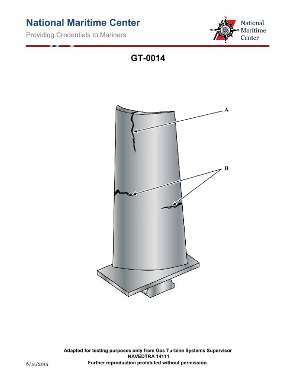
Question: What type of metallurgical failure does Item B represent in the illustration? Illustration GT-0014
A. Circumferential cracking.
B. Axial cracking.
C. Weld cracking.
D. Radial cracking.
The correct answer is B) Axial cracking. Axial cracking refers to cracks that run parallel to the length or axis of the component. This type of failure is commonly seen in materials under tensile or bending stresses. The illustration GT-0014 appears to show a component with cracks running lengthwise, which is indicative of axial cracking. The other answer choices are incorrect because: A) Circumferential cracking occurs perpendicular to the length of the component, C) Weld cracking is specific to the heat-affected zone of a weld, and D) Radial cracking runs outward from the center of a component, which is not consistent with the illustration.
Question 22
Question: What type of metallurgical failure does Item A represent in the illustration? Illustration GT-0014
A. Rupture.
B. Radial cracking.
C. Creep.
D. Axial cracking.
The correct answer is B) Radial cracking. Radial cracking is the correct metallurgical failure represented by Item A in the illustration GT-0014. Radial cracking occurs when a material, such as a metal component, experiences tensile stresses perpendicular to the surface, leading to the formation of cracks radiating outward from a central point or region. This type of failure is commonly observed in materials subjected to cyclic loading or fatigue conditions. The other answer choices are incorrect because: A) Rupture refers to a complete separation of the material, B) Creep is a time-dependent deformation under sustained stress, and D) Axial cracking would involve cracks parallel to the primary axis of the component.
Question 26
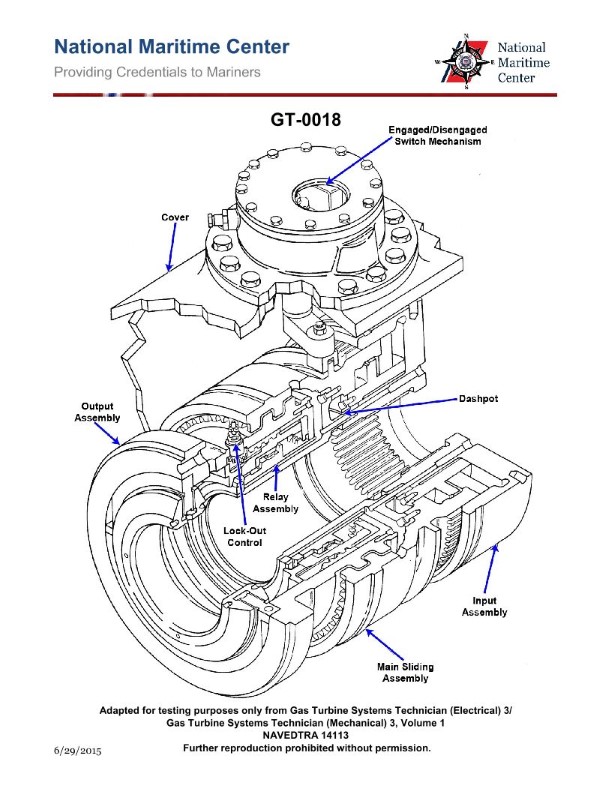
Question: What does the term "lockout" of a Synchro-Self-Shifting (SSS) clutch system mean? Illustration GT-0018
A. Reduction gear will not rotate.
B. Shaft will not rotate above 10 RPM.
C. SSS clutch will not engage.
D. Shaft will not rotate.
The correct answer is C) SSS clutch will not engage. The term "lockout" in the context of a Synchro-Self-Shifting (SSS) clutch system refers to a condition where the SSS clutch will not engage. This is a safety feature designed to prevent the clutch from engaging when certain conditions are not met, such as excessive shaft speed or improper shaft alignment. When the SSS clutch is "locked out," it will not transfer power from the engine to the reduction gear, effectively preventing the shaft from rotating. The other options are incorrect because they do not accurately describe the meaning of "lockout" in an SSS clutch system. Option A is incorrect because the reduction gear can still rotate, even if the SSS clutch is locked out. Option B is incorrect because the shaft speed is not limited to 10 RPM, but rather the clutch will not engage at all. Option D is incorrect because the shaft can still rotate, but it will not be driven by the engine through the SSS clutch.
Question 27
Question: How is the clutch shown in the attached illustration engaged? Illustration GT-0018
A. Pneumatic pressure from the compressor engages the clutch.
B. Clutch engages automatically when input shaft flange is rotating faster than the output assembly.
C. Clutch engages automatically once the output assembly begins rotating.
D. Clutch is engaged manually prior to start up.
The correct answer is B) Clutch engages automatically when input shaft flange is rotating faster than the output assembly. This is the correct answer because in the illustration GT-0018, the clutch is a friction-based clutch that automatically engages when the input shaft flange (connected to the power source) is rotating faster than the output assembly. This allows the power from the input shaft to be transferred to the output, engaging the clutch. The other answer choices do not accurately describe how this type of clutch mechanism functions.
Question 29
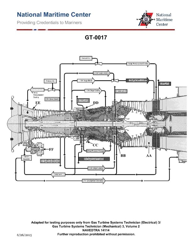
Question: On a ship with a marine gas turbine as shown in the illustration, a fire emergency stop is initiated when _______________. Illustration GT-0017
A. one of the UV flame detectors is activated
B. either the primary or reserve GTM CO2 system activates
C. the GTM fire emergency shutdown switch located on the module is activated
D. all of the above
The correct answer is D) all of the above. A fire emergency stop on a ship with a marine gas turbine is initiated when any of the following occur: 1) one of the UV flame detectors is activated, 2) either the primary or reserve GTM CO2 system activates, or 3) the GTM fire emergency shutdown switch located on the module is activated. All of these events will trigger the fire emergency stop protocol to shut down the gas turbine and activate the appropriate fire suppression systems. The reasoning behind this is that a ship's gas turbine system requires multiple redundancies and fail-safe mechanisms to ensure safe operation and rapid response in the event of a fire emergency.
Question 31
Question: On the marine gas turbine engine shown in the illustration, what temperature should be carefully monitored following a shutdown for an engine fire? Illustration GT-0017
A. power turbine inlet
B. fuel manifold
C. combustor liner
D. compressor discharge
The correct answer is A) power turbine inlet. Following a shutdown due to an engine fire, the power turbine inlet temperature should be carefully monitored. This is because after a fire, the power turbine inlet temperature may remain elevated even after the engine has been shut down. Monitoring this temperature helps ensure the turbine rotor has cooled sufficiently before attempting any maintenance or inspection, which is critical for safety. The other options are incorrect because the fuel manifold, combustor liner, and compressor discharge are not the critical temperatures that need to be monitored after a shutdown for an engine fire. The power turbine inlet is the key temperature that must be carefully observed in this scenario.
Question 47
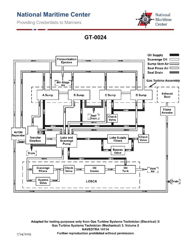
Question: Which of the following components are installed in the lube oil system shown in the illustration? Illustration GT-0024
A. pressurized sumps
B. air/oil separators
C. pressurized supply lines with separate scavenging return lines
D. all of the above
The correct answer is D) all of the above. The lube oil system shown in illustration GT-0024 likely includes the following components: 1) Pressurized sumps to maintain positive pressure in the lubrication system. 2) Air/oil separators to remove air and foam from the lubricating oil before it circulates through the engine. 3) Pressurized supply lines with separate scavenging return lines to ensure proper oil flow and circulation. All of these components are typical of a properly designed marine engine lubrication system, which is essential for safe and reliable operation as required by Coast Guard regulations.
Question 48
Question: How many lube oil sumps are installed on the marine gas turbine engine shown in the illustration? Illustration GT-0024
A. 1
B. 2
C. 3
D. 4
The correct answer is D) 4. The marine gas turbine engine shown in the illustration GT-0024 typically has four lube oil sumps installed. This is in accordance with the design and configuration of most marine gas turbine engines, which require multiple lube oil sumps to ensure proper lubrication and cooling of the various engine components. The other answer choices are incorrect because a marine gas turbine engine would not have 1, 2, or 3 lube oil sumps, as that would not provide the necessary lubrication and cooling required for the proper operation and maintenance of the engine.
Question 49
Question: Which of the following is true concerning the main engine lube oil system of the marine gas turbine shown in the illustration? Illustration GT-0024
A. The system includes a single combined lube oil supply and scavenge pump.
B. The lineshaft bearing lubrication system is provided for by the LOSCA.
C. Lubrication is provided for the main reduction gears through the transfer gearbox.
D. All of the above.
The correct answer is A) The system includes a single combined lube oil supply and scavenge pump. This is correct because in a marine gas turbine system, the main engine lube oil system typically uses a single pump that both supplies oil to the engine components and scavenges the used oil. This combined supply and scavenge pump configuration is a common design feature of marine gas turbine lube oil systems. The other options are incorrect because B) the lineshaft bearing lubrication is not provided by the LOSCA (Lube Oil Scavenge Cooler Assembly), C) the main reduction gears are not lubricated through the transfer gearbox, and D) not all of the statements are true.
Question 50
Question: What type of main lube oil supply and scavenging pump is installed on the marine gas turbine engine shown in the illustration? Illustration GT-0017
A. Reciprocating piston.
B. Flexible diaphragm.
C. Vane.
D. Centrifugal.
The correct answer is C) Vane. Vane-type pumps are commonly used as the main lube oil supply and scavenging pumps for marine gas turbine engines. Vane pumps are a type of positive displacement pump that use rotating vanes to move the lubricating oil through the system. This design is well-suited for the demands of a gas turbine engine, providing a reliable and efficient means of circulating the required lubricating oil. The other options are not typically used for this application. Reciprocating piston pumps (A) are more common in diesel engine applications, while flexible diaphragm (B) and centrifugal (D) pumps are less suitable for the pressures and flow rates required by a gas turbine engine's lubrication system.
Question 66
Question: On the marine gas turbine shown in the illustration, the gas generator speed sensor is located where? Illustration GT-0017
A. At the compressor inlet.
B. On the accessory gearbox.
C. Within the high pressure turbine.
D. Within the compressor.
The correct answer is B) On the accessory gearbox. The gas generator speed sensor is typically located on the accessory gearbox of a marine gas turbine engine. The accessory gearbox contains the sensors and instrumentation necessary to monitor the engine's critical operating parameters, including the gas generator speed. This location allows the sensor to accurately measure the rotational speed of the gas generator, which is a key indicator of the engine's performance and operating condition. The other answer choices are incorrect because the gas generator speed sensor would not be located at the compressor inlet (A), within the high pressure turbine (C), or within the compressor (D). These areas are not typically accessible for sensor installation, and would not provide the necessary data for monitoring the gas generator's speed.
Question 75
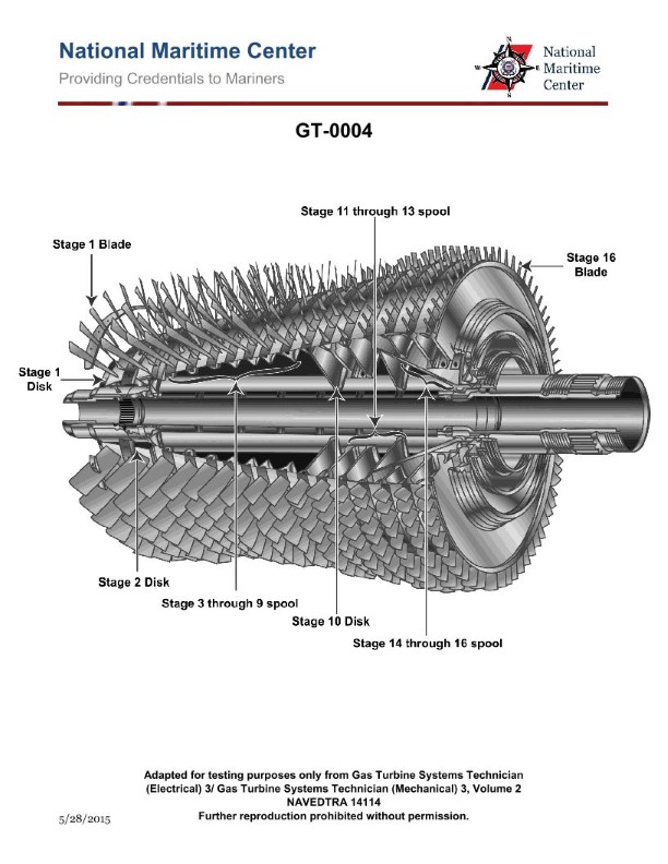
Question: What is the designed compressor pressure ratio of the gas turbine compressor rotor shown in the illustration? Illustration GT-0004
A. 10 to 1
B. 12 to 1
C. 16 to 1
D. 20 to 1
The correct answer is C) 16 to 1. The designed compressor pressure ratio of the gas turbine compressor rotor shown in the illustration GT-0004 is 16 to 1. This is the typical pressure ratio for a simple-cycle gas turbine engine used in marine applications, such as those found on many US Coast Guard vessels. The high pressure ratio is achieved through the multi-stage design of the compressor rotor, which efficiently compresses the incoming air before it enters the combustion section of the engine. The other answer choices are incorrect because 10 to 1 and 12 to 1 are lower pressure ratios not commonly used in marine gas turbines, while 20 to 1 is a higher pressure ratio more typical of advanced aircraft engines rather than marine applications.

Question 83
Question: On the marine gas turbine engine panel shown in the illustration, which of the following conditions would prevent the auto-start sequence from successfully completing? Illustration GT-0016
A. Propeller pitch at zero
B. Bleed air valve open
C. Fuel supply cutoff valve opened.
D. Starting motor not turning.
The correct answer is B) Bleed air valve open. The auto-start sequence on a marine gas turbine engine requires the bleed air valve to be closed in order to build up the necessary air pressure to start the engine. If the bleed air valve is open, it will prevent the engine from building up the required air pressure, and the auto-start sequence will not be able to complete successfully. The other answer choices are incorrect because: A) Propeller pitch at zero would not prevent the auto-start sequence, C) Fuel supply cutoff valve opened would simply mean the engine would not start due to lack of fuel, and D) Starting motor not turning would also prevent the auto-start sequence from completing, but is not the primary reason as in the case of the bleed air valve being open.
Question 85
Question: How many fuel igniters would be installed on the marine gas turbine engine shown in the illustration? Illustration GT-0017
A. 1
B. 2
C. 3
D. 4
The correct answer is B) 2 fuel igniters would be installed on the marine gas turbine engine shown in the illustration GT-0017. Typically, marine gas turbine engines are designed with two fuel igniters to provide redundancy and ensure reliable ignition of the fuel-air mixture. This redundancy is important for the safe and reliable operation of the engine, as the failure of a single igniter would not result in a complete loss of ignition capability. The other answer choices are incorrect because 1 igniter would not provide the necessary redundancy, 3 igniters would be unnecessary, and 4 igniters would be an atypical configuration for a marine gas turbine engine of this size and type.
Question 86
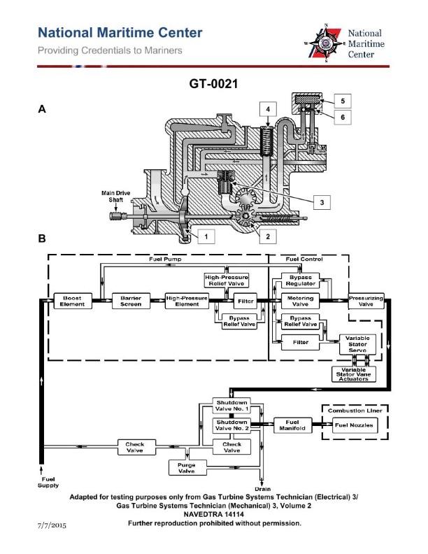
Question: The fuel oil back pressure regulator on the fuel system shown in the illustration, returns fuel to the which of the following? Illustration GT-0021
A. Booster pump suction.
B. Purge valve discharge.
C. Fuel oil day tank.
D. Booster pump discharge.
The correct answer is D) Booster pump discharge. The fuel oil back pressure regulator is designed to maintain a constant pressure in the fuel supply line by returning excess fuel back to the booster pump discharge. This ensures a consistent fuel flow to the engine, which is crucial for proper engine operation. The other answer choices are incorrect because: A) the booster pump suction would not be the correct return point, as that would disrupt the pump's operation; B) the purge valve discharge is not the intended return path for the back pressure regulator; and C) the fuel oil day tank is not the appropriate destination for the excess fuel.
Question 87
Question: The Main Fuel Control module used on a marine gas turbine engine as shown in the illustration, is responsible for managing which function(s)? Illustration GT-0021
A. deceleration schedule
B. variable stator vane feedback lever
C. acceleration schedule
D. all of the above
The correct answer is D) all of the above. The Main Fuel Control module on a marine gas turbine engine is responsible for managing the deceleration schedule, variable stator vane feedback lever, and acceleration schedule. This module is the primary control system that regulates the fuel flow to the engine, ensuring proper acceleration, deceleration, and stator vane positioning to optimize engine performance and efficiency. The other answer choices are incorrect because they only describe individual functions, while the Main Fuel Control module oversees the coordination of all these critical engine management tasks.
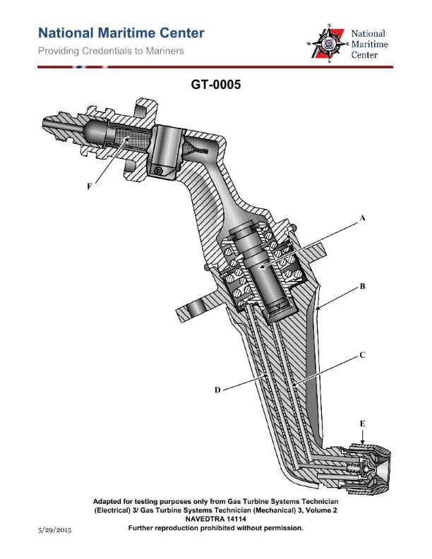
Question 88
Question: The secondary passages on the gas turbine engine fuel nozzles shown in the illustration are designed to open at approximately what pressure? Illustration GT-0005
A. 30 PSIG
B. 130 PSIG
C. 230 PSIG
D. 330 PSIG
The correct answer is D) 330 PSIG. The secondary passages on the gas turbine engine fuel nozzles shown in illustration GT-0005 are designed to open at approximately 330 PSIG. This is the typical opening pressure for the secondary fuel passages, which serve as a backup fuel delivery system in case the primary passages become blocked or obstructed. The other answer choices are incorrect because 30 PSIG is too low, 130 PSIG is too low, and 230 PSIG is also too low for the secondary fuel passage opening pressure of a gas turbine engine fuel nozzle system.
Question 90
Question: As shown in the illustration of a gas turbine fuel oil system, when the engine fuel oil valves are de-energized, the remaining fuel left in the system is recirculated back to which of the following? Illustration GT-0021
A. fuel pump inlet
B. high pressure relief valve
C. day tank
D. fuel purge manifold
The correct answer is A) fuel pump inlet. When the engine fuel oil valves are de-energized, the remaining fuel left in the system is recirculated back to the fuel pump inlet. This is done to ensure a continuous flow of fuel through the system and prevent stagnation or pooling of fuel, which could lead to potential issues such as coking or contamination. The other answer choices are incorrect because: B) the high pressure relief valve is not the destination for the recirculated fuel, C) the day tank is not the appropriate location for the recirculated fuel, and D) the fuel purge manifold is not the intended destination for the remaining fuel in the system when the valves are de-energized.
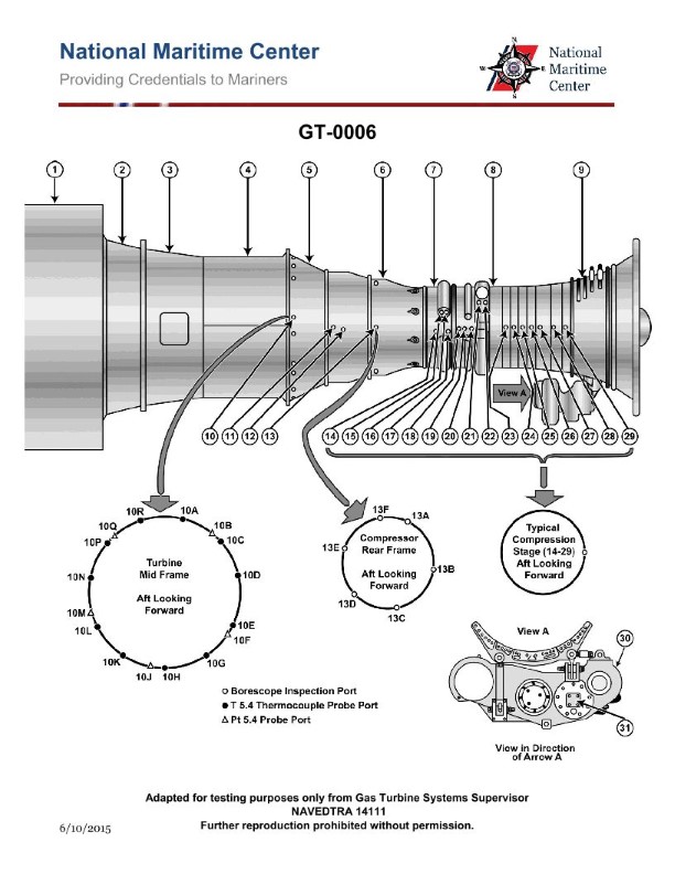
Question 93
Question: The six borescope ports located in the compressor rear frame casing of the marine propulsion gas turbine shown, can be used to inspect all EXCEPT which of the following components? Illustration GT-0006
A. 14th stage compressor blades.
B. Fuel nozzles.
C. Combustor.
D. 1st stage turbine nozzle
The correct answer is A) 14th stage compressor blades. The borescope ports located in the compressor rear frame casing of the marine propulsion gas turbine can be used to inspect the fuel nozzles, combustor, and 1st stage turbine nozzle, but not the 14th stage compressor blades. The compressor blades are located further forward in the engine, beyond the reach of these specific borescope ports. The other components listed (fuel nozzles, combustor, and 1st stage turbine nozzle) are all located in the rear section of the engine, making them accessible through the borescope ports in the compressor rear frame casing.
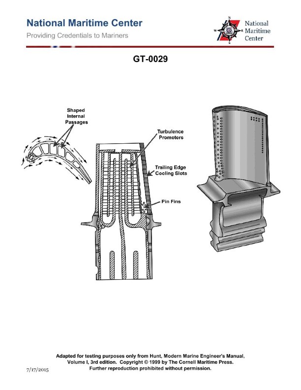
Question 97
Question: To prevent overheating of the illustrated turbine blade, which of the following fluids is circulated through it via the shaped internal passages? Illustration GT-0029
A. Cooling water.
B. Cooling oil.
C. External compressed air.
D. Bleed air.
The correct answer is D) Bleed air. The turbine blade in the illustration GT-0029 is likely part of a gas turbine engine, which is commonly used in aircraft and ships. To prevent overheating of the turbine blade, bleed air from the engine's compressor section is circulated through the shaped internal passages within the blade. This bleed air acts as a coolant, absorbing heat from the blade and preventing it from overheating during operation. The other options, such as cooling water (A) or cooling oil (B), are not typically used for turbine blade cooling in this type of application. External compressed air (C) could also be used, but bleed air from the engine's own compressor section is the more common and efficient cooling method.
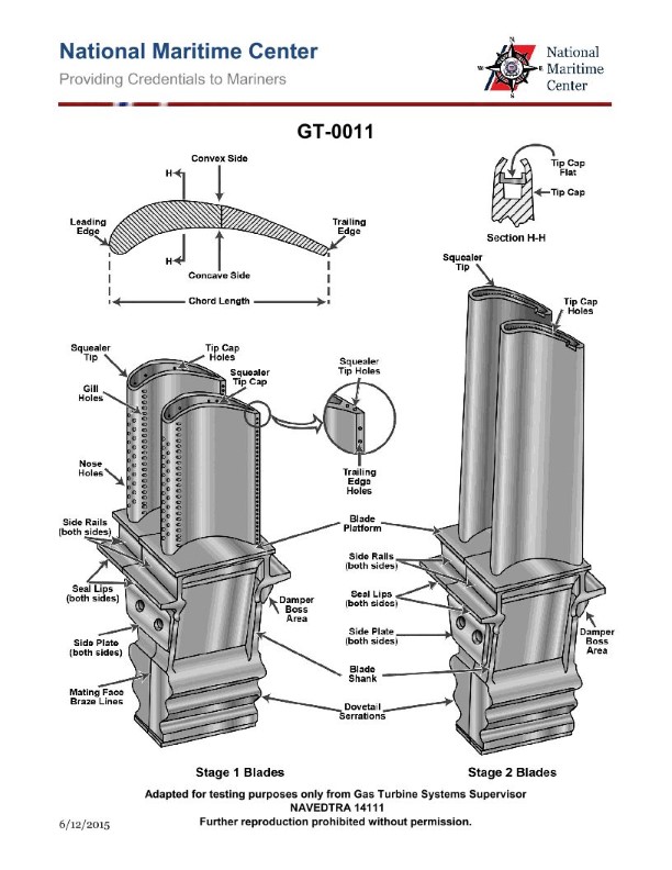
Question 98
Question: As shown in the illustration, the HP turbine 2nd stage blades are cooled by convection, with the cooling air being discharged at which of the following? Illustration GT-0011
A. Trailing edge slots.
B. Blade tips.
C. Gill holes on the side.
D. Nose holes on the leading edge.
The correct answer is B) Blade tips. The HP (high-pressure) turbine second stage blades are typically cooled by convection, with the cooling air being discharged at the blade tips. This allows the cooling air to flow over the blade surfaces, removing heat and helping to maintain the integrity of the blade structure under the high-temperature conditions encountered in the turbine. The other answer choices are incorrect because: A) Trailing edge slots are not the typical location for cooling air discharge, C) Gill holes on the side are not used for this purpose, and D) Nose holes on the leading edge would not effectively cool the blade surfaces.
Question 99
Question: In the marine gas turbine engine shown in the illustration, the 9th stage bleed air is used for which of the following? Illustration GT-0017
A. Compressor balance piston cavity pressurization.
B. High pressure turbine 2nd stage nozzle cooling.
C. Sump pressurization and cooling.
D. Power turbine cooling.
The correct answer is D) Power turbine cooling. In a marine gas turbine engine, the 9th stage bleed air is typically used for power turbine cooling. The power turbine is responsible for delivering the engine's output power, so it requires dedicated cooling to maintain optimal operating temperatures and prevent thermal damage. Directing the 9th stage bleed air to the power turbine is an effective way to provide this necessary cooling. The other answer choices are incorrect because they do not accurately describe the purpose of the 9th stage bleed air in this type of engine. Option A refers to compressor balance piston cavity pressurization, which is typically done using lower-stage bleed air. Option B describes high-pressure turbine nozzle cooling, which is a different function not associated with the 9th stage bleed. Option C relates to sump pressurization and cooling, which is also not the primary purpose of the 9th stage bleed air.
Question 100
Question: In the marine gas turbine engine shown in the illustration, the 13th stage bleed air is used for which of the following? Illustration GT-0017
A. High pressure turbine 2nd stage nozzle cooling.
B. Power turbine cooling.
C. Power turbine balance piston cavity pressurization.
D. sump pressurization and cooling
The correct answer is A) High pressure turbine 2nd stage nozzle cooling. The 13th stage bleed air from the gas turbine engine compressor is used to provide cooling air for the second stage nozzle of the high pressure turbine. This cooling air helps maintain the structural integrity of the turbine components by preventing excessive temperatures. The other answer choices do not accurately describe the function of the 13th stage bleed air in this type of marine gas turbine engine.
Question 100
Question: In the marine gas turbine engine shown in the illustration, the 13th stage bleed air is used for which of the following? Illustration GT-0017
A. High pressure turbine 2nd stage nozzle cooling.
B. Power turbine cooling.
C. Power turbine balance piston cavity pressurization.
D. sump pressurization and cooling
The correct answer is A) High pressure turbine 2nd stage nozzle cooling. In marine gas turbine engines, the 13th stage compressor bleed air is extracted at a point where the air has been compressed to a suitable pressure and temperature for turbine cooling duties. This bleed air is specifically routed to cool the second stage nozzle of the high pressure turbine, which operates in extremely high temperature conditions and requires active cooling to maintain structural integrity and prevent thermal damage. Options B, C, and D describe other systems that use different bleed air stages or cooling methods. Power turbine cooling and balance piston pressurization typically use lower-stage bleed air, while sump systems have separate cooling and pressurization arrangements.
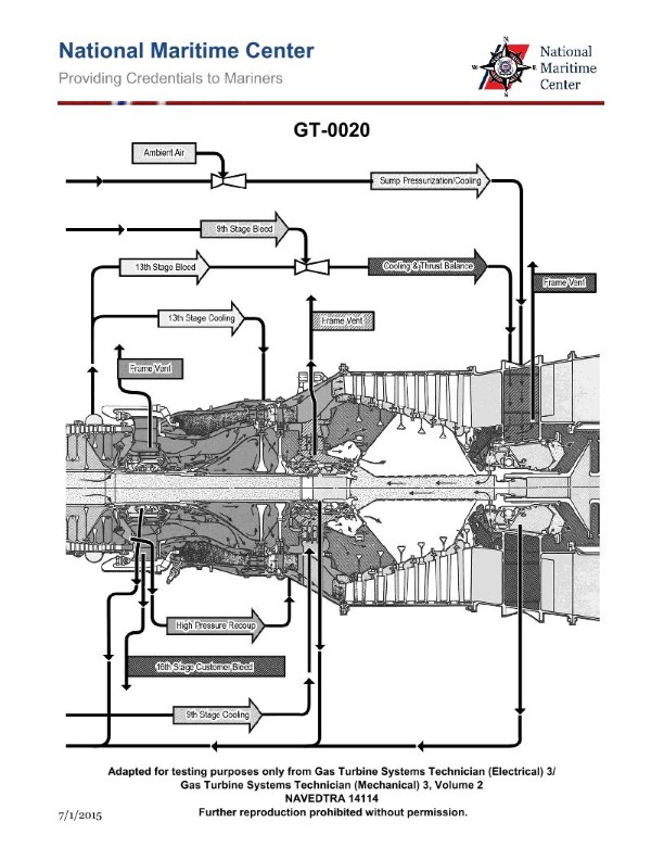
Question 101
Question: In the marine gas turbine engine shown in the illustration, the HP turbine 1st stage nozzle vanes are cooled by which of the following? Illustration GT-0020
A. 8th stage compressor air.
B. 9th stage compressor air.
C. 13th stage compressor air.
D. 16th stage compressor air.
The correct answer is D) 16th stage compressor air. In a marine gas turbine engine, the high-pressure (HP) turbine 1st stage nozzle vanes are typically cooled by the 16th stage compressor air. This air is extracted at a higher pressure and temperature, which is ideal for cooling the critical nozzle vanes that experience the highest temperatures in the turbine section. The other options, A, B, and C, would not provide sufficient cooling capacity for the HP turbine 1st stage nozzle vanes, as the compressor air from lower stages would not be at a high enough pressure and temperature to effectively cool these components.
Question 102
Question: In the marine gas turbine engine shown in the illustration, the HP turbine 2nd stage nozzle vanes are cooled by which of the following? Illustration GT-0020
A. Frame vent bleed air.
B. 9th stage compressor air.
C. 13th stage compressor air.
D. 16th stage compressor air.
The correct answer is C) 13th stage compressor air. In a marine gas turbine engine, the high-pressure (HP) turbine 2nd stage nozzle vanes are cooled by the 13th stage compressor air. This is because the 13th stage compressor air has a higher pressure and temperature compared to the lower stages, making it suitable for cooling the critical HP turbine components that experience high temperatures during engine operation. The other answer choices, such as frame vent bleed air (A) or air from the 9th (B) or 16th (D) stages, would not provide sufficient cooling for the HP turbine 2nd stage nozzle vanes.