Pass Your Coast Guard Licensing Exams!
Study offline, track your progress, and simulate real exams with the Coast Guard Exams app
Gas Turbine - Assistant
25 images
Question 25
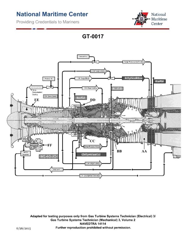
Question: Which of the following statements is true concerning the fuel oil ignition system of the gas turbine engine shown in the illustration? Illustration GT-0017
A. The igniters will only energize if the exhaust gas temperature falls below a preset value.
B. The igniters will de-energize when the power turbine exceeds a preset RPM.
C. The igniters will de-energize when the gas generator exceeds a preset RPM.
D. The igniters remain energized throughout the normal operation of the engine.
The correct answer is C) The igniters will de-energize when the gas generator exceeds a preset RPM. This is correct because in a gas turbine engine, the igniters are used to initiate combustion during engine start-up. Once the gas generator reaches a preset RPM, the igniters are automatically de-energized as the engine is able to sustain combustion without them. The other options are incorrect because A) the igniters are not controlled by exhaust gas temperature, B) the igniters are not controlled by the power turbine RPM, and D) the igniters do not remain energized throughout normal engine operation.
Question 46
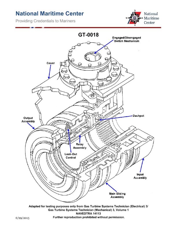
Question: How is the clutch shown in the attached illustration engaged? Illustration GT-0018
A. Pneumatic pressure from the compressor engages the clutch.
B. Clutch engages automatically when input shaft flange is rotating faster than the output assembly.
C. Clutch is engaged manually prior to start up.
D. Clutch engages automatically once the output assembly begins rotating.
The correct answer is B) Clutch engages automatically when input shaft flange is rotating faster than the output assembly. The clutch shown in the illustration GT-0018 is likely a friction-based clutch mechanism. In such systems, the clutch automatically engages when the input shaft (connected to the prime mover) is rotating faster than the output assembly. This allows the transfer of power from the input to the output, engaging the clutch without any manual intervention. The other answer choices are incorrect because: A) Pneumatic pressure is not the mechanism for engaging this type of clutch; C) The clutch is not engaged manually prior to startup; and D) The clutch does not engage automatically once the output assembly begins rotating, but rather when the input shaft is rotating faster.
Question 50
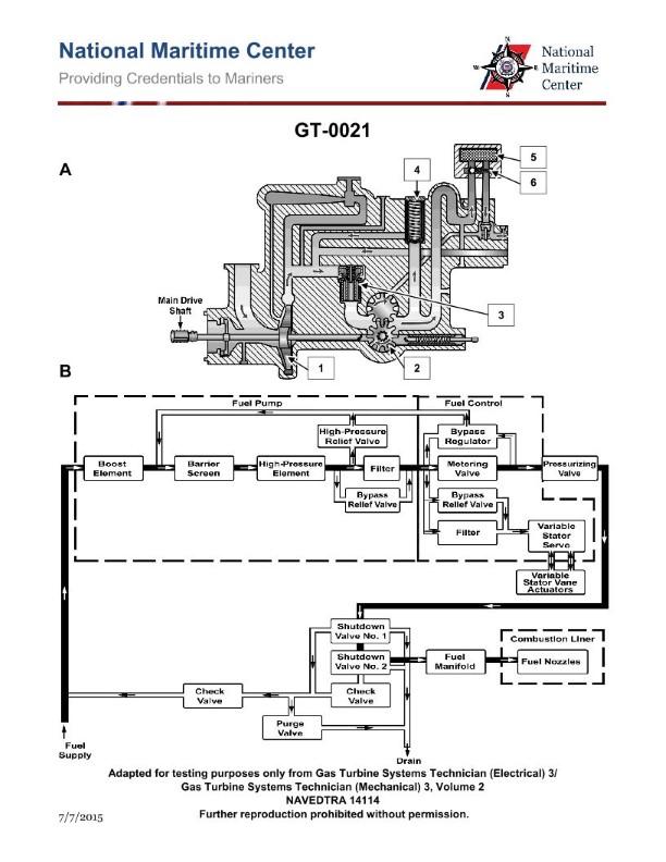
Question: As shown in the illustration of a gas turbine fuel oil system, when the engine fuel oil valves are de-energized, the remaining fuel left in the system is recirculated back to which of the following? Illustration GT-0021
A. Day tank.
B. High pressure relief valve.
C. Fuel purge manifold.
D. Fuel pump inlet.
The correct answer is D) Fuel pump inlet. When the engine fuel oil valves are de-energized, the remaining fuel left in the system is recirculated back to the fuel pump inlet. This is because the fuel system is designed to ensure a continuous supply of fuel to the engine, even when the valves are closed. By recirculating the fuel back to the inlet of the fuel pump, the system maintains a constant flow and pressure, preventing potential issues with the engine's fuel supply. The other options are incorrect because they do not represent the proper path for the recirculated fuel. The day tank, high-pressure relief valve, and fuel purge manifold are not the destinations for the recirculated fuel when the engine fuel oil valves are de-energized.
Question 52
Question: For the GE LM2500 gas turbine shown in the illustration, the 9th stage bleed air is used for which of the following? Illustration GT-0017
A. High pressure turbine 2nd stage nozzle cooling.
B. Compressor balance piston cavity pressurization.
C. Power turbine cooling.
D. Sump pressurization and cooling.
The correct answer is C) Power turbine cooling. The 9th stage bleed air from the GE LM2500 gas turbine is used for power turbine cooling. The power turbine is responsible for extracting power from the high-pressure turbine exhaust to drive the compressor. Directing the high-pressure, high-temperature 9th stage bleed air to the power turbine helps cool the blades and other components, improving efficiency and preventing thermal damage. The other answer choices are incorrect because: A) is for the high-pressure turbine, not the power turbine; B) is for the compressor balance piston, not the power turbine; and D) is for sump pressurization and cooling, not the power turbine.
Question 53
Question: For the GE LM2500 gas turbine engine shown in the illustration, the 13th stage bleed air is used for which of the following? Illustration GT-0017
A. Sump pressurization and cooling.
B. Power turbine balance piston cavity pressurization.
C. Power turbine cooling.
D. High pressure turbine 2nd stage nozzle cooling.
The correct answer is D) High pressure turbine 2nd stage nozzle cooling. The 13th stage bleed air from the GE LM2500 gas turbine engine is used for high pressure turbine 2nd stage nozzle cooling. This cooling air is extracted from the compressor section and routed to the turbine section to provide essential cooling for the high pressure turbine components, which operate at extremely high temperatures. The other answer choices, while potentially valid for other engine systems, do not accurately describe the purpose of the 13th stage bleed air in this particular engine configuration.
Question 55
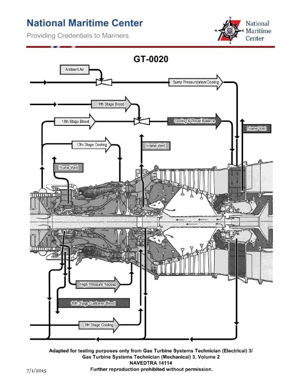
Question: For the GE LM2500 gas turbine engine shown in the illustration, the HP turbine 2nd stage nozzle vanes are cooled by which of the following? Illustration GT-0020
A. Frame vent bleed air.
B. 13th stage compressor air.
C. 16th stage compressor air.
D. 9th stage compressor air.
The correct answer is B) 13th stage compressor air. The HP turbine 2nd stage nozzle vanes in the GE LM2500 gas turbine engine are cooled by 13th stage compressor air. This is because the 13th stage of the compressor provides the highest pressure and temperature air within the engine, which is necessary to effectively cool the critical HP turbine nozzle vanes. The other answer choices are incorrect because frame vent bleed air (A) is not hot enough to provide adequate cooling, and the 16th stage (C) and 9th stage (D) compressor air does not have the required pressure and temperature characteristics to cool the HP turbine nozzle vanes.
Question 56
Question: For the GE LM2500 gas turbine engine shown in the illustration, the HP turbine 1st stage nozzle vanes are cooled by which of the following? Illustration GT-0020
A. 8th stage compressor air.
B. 9th stage compressor air.
C. 13th stage compressor air.
D. 16th stage compressor air.
The correct answer is D) 16th stage compressor air. The HP turbine 1st stage nozzle vanes in the GE LM2500 gas turbine engine are cooled by the 16th stage compressor air. This is because the 16th stage compressor air has the highest pressure and temperature, making it the most suitable source for cooling the high-pressure turbine components that are exposed to the highest temperatures in the engine. The other options, A) 8th stage, B) 9th stage, and C) 13th stage compressor air, are not correct because they do not have the necessary pressure and temperature characteristics to effectively cool the HP turbine 1st stage nozzle vanes.
Question 57
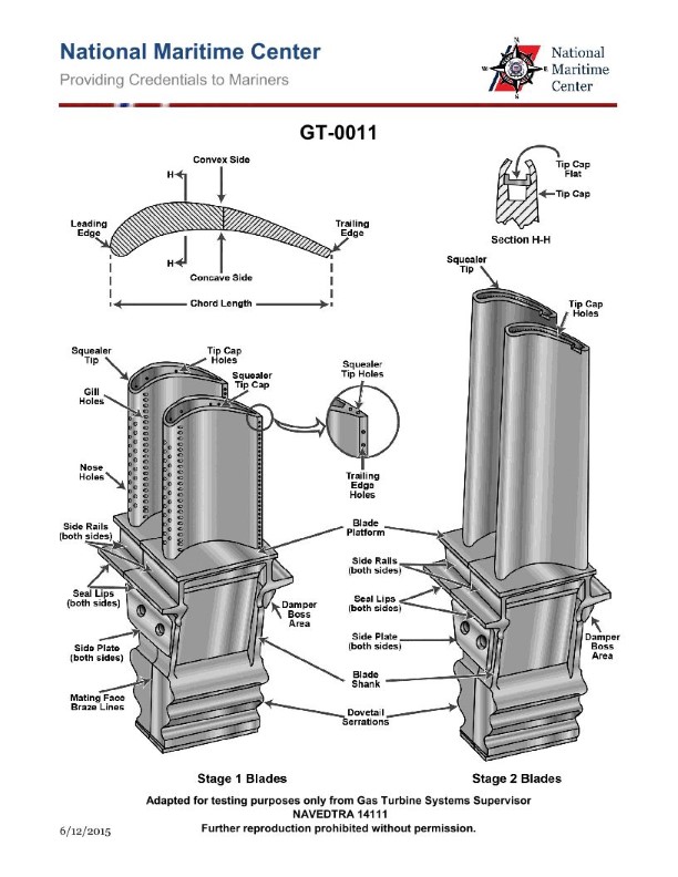
Question: For the GE LM2500 gas turbine engine shown in the illustration, the HP turbine 2nd stage blades are cooled by convection, with the cooling air being discharged where? Illustration GT-0011
A. Nose holes on the leading edge.
B. Gill holes on the side.
C. Trailing edge slots.
D. Blade tips.
The correct answer is D) Blade tips. The HP (high-pressure) turbine 2nd stage blades in the GE LM2500 gas turbine engine are cooled by convection, with the cooling air being discharged through the blade tips. This design allows the cooling air to flow over the blade surfaces, effectively dissipating heat and improving the engine's overall efficiency. The other answer options are incorrect because: A) Nose holes on the leading edge are not used for cooling the HP turbine 2nd stage blades, B) Gill holes on the side are not the discharge point for the cooling air, and C) Trailing edge slots are not the location where the cooling air is expelled.
Question 67
Question: If the lube oil scavenge temperature exceeds 300 degrees Fahrenheit on the gas turbine engine shown in the illustration, and reducing power does NOT bring the temperature within limits, the operator should do which of the following? Illustration GT-0017
A. Continue to operate at the reduced power level.
B. Monitor the temperature while continuing to operate.
C. Continue to reduce power on the engine.
D. Shutdown the engine and troubleshoot.
The correct answer is D) Shutdown the engine and troubleshoot. If the lube oil scavenge temperature exceeds 300 degrees Fahrenheit on a gas turbine engine, and reducing power does not bring the temperature within limits, the operator should shut down the engine and troubleshoot the issue. This is because an excessively high lube oil temperature can indicate a serious problem with the engine, such as a malfunctioning component or lack of proper lubrication. Continuing to operate the engine in this condition could lead to catastrophic failure. The safest and most appropriate action is to shut down the engine and thoroughly inspect and repair the issue before attempting to restart it. The other options are incorrect because they do not address the severity of the situation. Continuing to operate at a reduced power level or simply monitoring the temperature could allow the problem to worsen and potentially cause engine damage. Further reducing power may not be sufficient to bring the temperature within acceptable limits.
Question 70
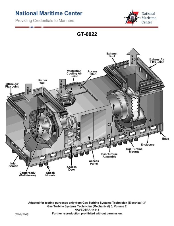
Question: When removing the gas turbine engine as shown in the illustration, how is the engine removal accomplished? Illustration GT-0022
A. By removing the inlet screen, barrier wall and module front panel, then installing the rails and moving the engine into the engine room and up through the soft patch to the main deck.
B. By removing the exhaust boot, HSCS and PT, then lifting the engine up the exhaust stack.
C. By removing the inlet screen and barrier wall, then installing the rails and lifting the engine out through the inlet duct.
D. By removing the upper half casing and separately lifting out the compressor and power turbine rotors.
The correct answer is A) By removing the inlet screen, barrier wall and module front panel, then installing the rails and moving the engine into the engine room and up through the soft patch to the main deck. This is the correct answer because it accurately describes the typical procedure for removing a gas turbine engine, such as the one shown in the illustration GT-0022. The inlet screen, barrier wall, and module front panel need to be removed to access the engine, and then rails are installed to allow the engine to be carefully moved into the engine room and lifted up through the soft patch (an opening in the deck) to the main deck. The other answer choices are incorrect because they do not accurately describe the full engine removal process. Removing only the exhaust boot, HSCS, and PT (answer B) would not allow the entire engine to be removed. Removing the inlet screen and barrier wall but lifting the engine out through the inlet duct (answer C) is also not the typical procedure. Separately lifting out the compressor and power turbine rotors (answer D) is a more involved process that would not be the standard engine removal method.
Question 100
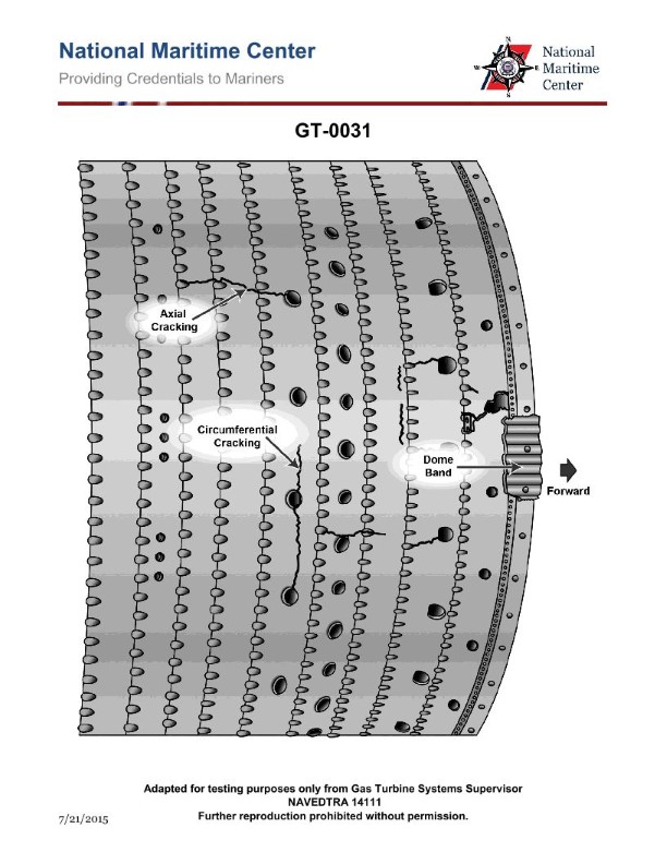
Question: Why is the cycle efficiency higher in the intercooled-recuperated cycle as compared to a simple cycle gas turbine? Illustration GT-0031
A. The intercooler serves to increase the required high-pressure compressor power while the recuperator utilizes waste heat form the exhaust to decrease turbine inlet temperature.
B. The intercooler serves to increase the required high-pressure compressor power while the recuperator utilizes waste heat form the exhaust to increase turbine inlet temperature.
C. The intercooler serves to reduce the required high-pressure compressor power while the recuperator utilizes waste heat form the exhaust to decrease required fuel to achieve the turbine inlet temperature.
D. The intercooler serves to reduce the required high-pressure compressor power while the recuperator utilizes waste heat form the exhaust to decrease turbine inlet temperature.
The correct answer is C. The intercooled-recuperated cycle has higher cycle efficiency compared to a simple cycle gas turbine because: 1) The intercooler serves to reduce the required high-pressure compressor power by cooling the air between the low-pressure and high-pressure compressor stages. This reduces the work input required for compression. 2) The recuperator utilizes the waste heat from the turbine exhaust to preheat the air before it enters the combustor. This reduces the required fuel input to achieve the desired turbine inlet temperature, improving the overall cycle efficiency. The other options are incorrect because they do not accurately describe the effects of the intercooler and recuperator on the cycle performance. Specifically, the intercooler does not increase the compressor power, and the recuperator does not decrease the turbine inlet temperature.
Question 107
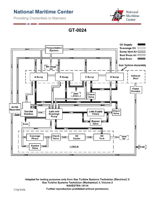
Question: For the gas turbine engine lube oil system shown in the illustration, what is the purpose of the lube oil supply check valves? Illustration GT-0024
A. Keep the lube oil lines in the engine primed.
B. Prevent lube oil contained in the LO storage and conditioning tank from draining into gearboxes and sumps.
C. Prevent the lube oil and scavenge pump from losing its prime.
D. All of the above.
The correct answer is B) Prevent lube oil contained in the LO storage and conditioning tank from draining into gearboxes and sumps. The lube oil supply check valves in the gas turbine engine lube oil system serve to prevent the lube oil stored in the LO storage and conditioning tank from draining back into the engine's gearboxes and sumps when the engine is not running. This ensures that the lube oil remains in the designated storage tank, ready to be distributed to the engine components when the engine is started and the lube oil pumps are activated. The other answer choices, while related to the lube oil system, do not accurately describe the primary purpose of the lube oil supply check valves in this specific system configuration.
Question 108
Question: The lube oil scavenge pressure on the marine gas turbine shown in the illustration is sensed by which of the following? Illustration GT-0017
A. Manometer.
B. RTD.
C. Transducer.
D. Probe.
The correct answer is C) Transducer. The lube oil scavenge pressure on the marine gas turbine is sensed by a transducer. A transducer is a device that converts one form of energy into another, in this case, converting the mechanical pressure into an electrical signal that can be monitored and used for control purposes. This is the standard method for measuring pressures in marine gas turbine systems. The other options are incorrect because: A) A manometer is used to measure pressure visually, not electronically. B) An RTD (Resistance Temperature Detector) is used to measure temperature, not pressure. D) A probe is a general term that does not specifically indicate the sensing mechanism, which in this case is a transducer.
Question 109
Question: While standing watch on a ship equipped with the gas turbine engine shown in the illustration, a fire emergency stop is initiated when which of the following situations occur? Illustration GT-0017
A. either the primary or reserve GTM CO2 system activates
B. the GTM fire emergency shutdown switch located on the module is activated
C. one of the UV flame detectors is activated
D. All of the above
The correct answer is D) All of the above. In a gas turbine engine system, a fire emergency stop can be initiated when any of the following situations occur: 1) Either the primary or reserve GTM (gas turbine module) CO2 fire suppression system activates 2) The GTM fire emergency shutdown switch located on the module is manually activated 3) One of the UV (ultraviolet) flame detectors senses a fire and triggers the emergency shutdown All three of these scenarios would properly initiate the gas turbine fire emergency stop procedure, as per Coast Guard regulations and industry best practices for ensuring the safe operation of gas turbine engine systems on ships.
Question 122
Question: All clock positions, engine references, and enclosure references apply to viewing the gas turbine engine shown in the illustration from which of the following locations? Illustration GT-0017
A. Right side of the compressor to the left side.
B. Left side of the power turbine to the right side.
C. Intake end, looking toward the exhaust end.
D. Rear (exhaust end), looking toward the intake end.
The correct answer is D) Rear (exhaust end), looking toward the intake end. This is correct because when viewing a gas turbine engine illustration, the standard orientation is from the rear (exhaust end) looking toward the intake end. All references to clock positions, engine components, and enclosures will be based on this viewpoint. The other answer choices describe different orientations that do not match the standard convention for interpreting gas turbine engine illustrations.
Question 134
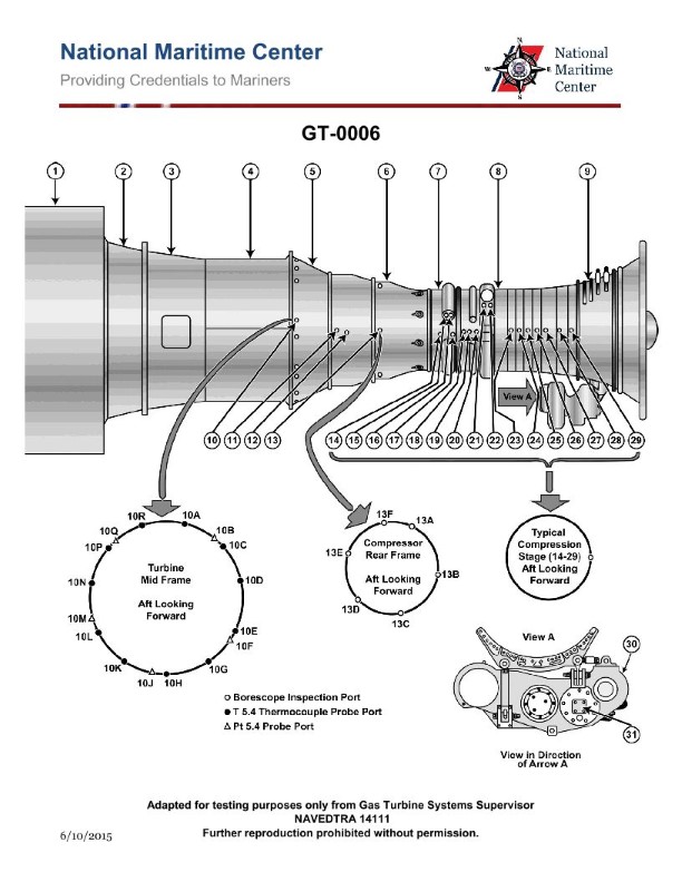
Question: What type of engine starter motor is commonly found on the marine gas turbine shown in the illustration? Illustration GT-0006
A. Hydraulic motor
B. AC synchronous motor
C. AC induction motor
D. DC series wound electric motor
The correct answer is A) Hydraulic motor. Marine gas turbine engines commonly use hydraulic starter motors to initiate the engine's rotation during startup. Hydraulic motors are well-suited for this application due to their high torque output and ability to provide the necessary cranking power to start the turbine engine. Other options like AC or DC electric motors would not be as suitable for this high-power starting requirement. The other answer choices are incorrect because AC synchronous and induction motors are not typically used to start gas turbine engines, and a DC series wound electric motor would not have the torque capacity needed for this application.
Question 141
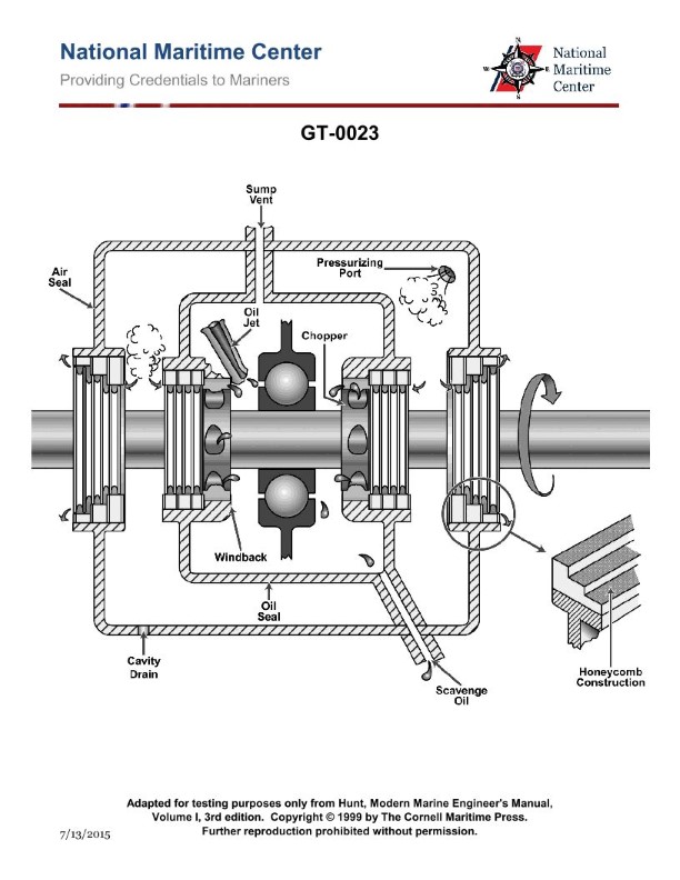
Question: The lube oil system shown in the illustration, is designed to lubricate the main bearings by what principle? Illustration GT-0023
A. Spray lubrication with dry sumps.
B. Totally submerged oil bath.
C. Splash lubrication.
D. Self-contained partial oil bath.
The correct answer is A) Spray lubrication with dry sumps. The lube oil system shown in the illustration GT-0023 is designed to lubricate the main bearings using the principle of spray lubrication. In this system, the oil is pumped from a dry sump (not a submerged oil bath) and sprayed onto the main bearings, providing a continuous supply of lubrication. This method is commonly used in marine diesel engines to ensure effective lubrication while minimizing the amount of oil required. The other options are incorrect because B) a totally submerged oil bath is not the principle used in this system, C) splash lubrication relies on the motion of the crankshaft to distribute the oil, and D) a self-contained partial oil bath is a different lubrication system that is not depicted in the illustration.
Question 142
Question: As shown in the illustration, what is the purpose of pressurizing the main bearing lube oil sumps on a typical marine gas turbine? Illustration GT-0023
A. Provides uniform lube oil distribution around the bearing.
B. Minimizes oil leakage from the rotor shaft.
C. Increases lube oil penetration.
D. Assist in cooling the lube oil.
The correct answer is B) Minimizes oil leakage from the rotor shaft. The main purpose of pressurizing the lube oil sumps on a marine gas turbine is to create a positive pressure within the bearing housing, which helps to prevent oil leakage from the rotor shaft. This positive pressure ensures that any potential leakage paths are sealed, reducing the risk of oil escaping the bearing housing and potentially causing operational issues or environmental contamination. The other answer choices are incorrect because: A) Uniform oil distribution is achieved through the design of the lubrication system, not specifically by pressurizing the sumps. C) Increased oil penetration is not the primary purpose of pressurizing the sumps. D) Cooling the oil is a separate function, typically handled by the oil cooler or heat exchanger, not the pressurization system.
Question 143
Question: On the gas turbine engine lube oil system shown in the illustration, air and oil are primarily separated in the air/oil separator through the use of which of the following? Illustration GT-0024
A. Filter
B. Impeller
C. Heater
D. Strainer
The correct answer is B) Impeller. In a gas turbine engine lube oil system, the air and oil are primarily separated in the air/oil separator through the use of an impeller. The impeller spins rapidly, creating a centrifugal force that separates the lighter air from the heavier oil, allowing the oil to be recirculated back into the system while the air is vented out. The other options are incorrect because a filter, heater, or strainer are not the primary means of separating the air and oil in this type of system. These components may be present in the system, but they do not perform the primary air/oil separation function.
Question 144
Question: On the marine gas turbine engine shown in the illustration, the 8th stage bleed air is used for which of the following? Illustration GT-0017
A. Power turbine balance piston cavity pressurization.
B. Lube oil sump pressurization and cooling.
C. High pressure turbine 2nd stage nozzle cooling.
D. Power turbine blade cooling.
The correct answer is B) Lube oil sump pressurization and cooling. The 8th stage bleed air from the marine gas turbine engine is used to pressurize and cool the lube oil sump. This is a common application of the compressor bleed air in turbine engine design. The pressurization helps to circulate the lube oil and prevent oil foaming, while the cooling helps to maintain the proper oil temperature for lubrication and bearing performance. The other answer choices are incorrect because: A) is for the power turbine, not the compressor section; C) is for the high pressure turbine section, not the 8th stage; and D) is for the power turbine blades, not the lube oil system.
Question 145
Question: The lube oil system shown in the illustration, consists of which of the following sub-systems? Illustration GT-0024
A. Lube oil scavenging.
B. Sump venting.
C. Lube oil supply.
D. All of the above.
The correct answer is D) All of the above. The lube oil system shown in the illustration GT-0024 consists of the following sub-systems: 1. Lube oil scavenging - This system removes used oil from the engine's crankcase and circulates it back to the lube oil sump. 2. Sump venting - This system allows air and vapors to be vented from the lube oil sump, preventing pressure buildup. 3. Lube oil supply - This system delivers clean, pressurized lube oil from the sump to the engine's moving parts, such as bearings and gears, to reduce friction and wear. All three of these sub-systems are essential components of a complete lube oil system, which is required for the proper lubrication and operation of the engine.
Question 146
Question: What is the purpose of the air/oil separator shown in the illustration of the gas turbine lube oil system? Illustration GT-0024
A. Minimize oil consumption by separating oily vapors being vented to the atmosphere.
B. Reduce oil foaming.
C. Maintain oil pressure in the sumps.
D. All of the above.
The correct answer is A) Minimize oil consumption by separating oily vapors being vented to the atmosphere. The purpose of the air/oil separator in a gas turbine lube oil system is to minimize oil consumption by separating oily vapors from the air being vented to the atmosphere. This helps prevent the loss of lubricating oil, which would otherwise be discharged into the environment. The air/oil separator achieves this by mechanically removing the oil mist from the vent air, allowing the oil to be returned to the system while the cleaned air is safely vented. The other options are incorrect because they do not fully capture the primary purpose of the air/oil separator, which is to conserve lubricating oil and prevent environmental pollution.
Question 154
Question: Routine water washing of the gas turbine engine compressor shown in the illustration, is usually performed while operating under which of the following conditions? Illustration GT-0017
A. At 25% power.
B. At 75% power.
C. At full power.
D. With the starter motor drive.
The correct answer is D) With the starter motor drive. The routine water washing of the gas turbine engine compressor is typically performed with the starter motor drive, not at specific power settings. This is done to ensure the compressor blades are thoroughly cleaned while the engine is not under load, which helps maintain the engine's efficiency and performance. The other options, A) 25% power, B) 75% power, and C) full power, are incorrect because the compressor water washing is not usually conducted at those specific power settings. The key is to perform the water washing with the starter motor drive to properly clean the compressor blades without putting the engine under load.

Question 156
Question: When auto starting a gas turbine engine similar to the one shown in the illustration, a "False Start" indication will initiate if which of the following conditions occurs? Illustration GT-0016
A. The gas generator rotor fails to reach a preset RPM after the power turbine begins to rotate.
B. The gas generator rotor fails to reach a preset RPM after the starting motor has been energized for a preset interval.
C. Power Turbine outlet temperature fails to reach a preset value.
D. The power turbine fails to reach a preset RPM after the gas generator reaches a preset RPM.
The correct answer is B) The gas generator rotor fails to reach a preset RPM after the starting motor has been energized for a preset interval. This is because during the auto-start sequence of a gas turbine engine, the engine control system monitors the gas generator rotor speed. If the gas generator rotor does not reach a preset RPM within a specified time after the starting motor is energized, the system will register a "False Start" indication. This indicates that the engine has failed to start properly and requires further troubleshooting. The other options are incorrect because they do not accurately describe the specific condition that triggers a "False Start" indication during the auto-start sequence. Option A is incorrect as it refers to the power turbine, not the gas generator rotor. Options C and D are also incorrect as they do not involve the gas generator rotor speed during the initial start-up phase.
Question 157
Question: During an auto-start sequence on the marine gas turbine control console shown in the illustration, what would be the correct order of events required to occur after the start sequence begins? Illustration GT-0016
A. NGG reaches idle RPM, Power turbine reaches ignition RPM, gas temperature greater than 400 degrees F.
B. NGG reaches ignition RPM, gas temperature greater than 400 degrees F, NGG reaches idle RPM
C. Power turbine reaches ignition RPM, gas temperature greater than 400 degrees F, Power turbine reaches idle RPM
D. Power turbine reaches ignition RPM, gas temperature greater than 400 degrees F, NGG reaches idle RPM
The correct answer is B) NGG reaches ignition RPM, gas temperature greater than 400 degrees F, NGG reaches idle RPM. During the auto-start sequence of a marine gas turbine, the first critical event is the NGG (gas generator) reaching its ignition RPM. This allows the fuel to be ignited and the turbine to begin generating power. Next, the gas temperature must rise above 400 degrees F to indicate successful ignition. Finally, the NGG must reach its idle RPM, indicating the turbine is operating at a stable, self-sustaining level. The other options are incorrect because they do not follow the proper sequence of events required for a successful gas turbine start-up.