Pass Your Coast Guard Licensing Exams!
Study offline, track your progress, and simulate real exams with the Coast Guard Exams app
Electricity & Electronics - 1st Asst/Chief
106 images
Question 1
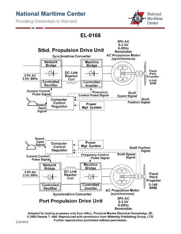
Question: As shown in the illustrated electric propulsion control scheme for a twin screw vessel, when the two shaft speeds are within 5% of each other, the bridge may select "shaft synchro- phasing mode". What statement is true regarding the purpose of this operating mode? Illustration EL-0168
A. Vibration sensors are used to achieve identical shaft speeds and propeller synchronization to minimize vibration.
B. The respective shaft speed sensors alone are used to achieve identical shaft speeds without regard to propeller position to achieve even power development.
C. The respective shaft speed and shaft position sensors are used to achieve identical shaft speeds and propeller synchronization to minimize shaft vibration.
D. Cavitation sensors are used to achieve identical shaft speeds and propeller synchronization to minimize vibration.
The correct answer is C. The purpose of the "shaft synchro-phasing mode" is to achieve identical shaft speeds and propeller synchronization in order to minimize shaft vibration. This is accomplished by using both the respective shaft speed and shaft position sensors to ensure the propellers are rotating in sync. The other options are incorrect because: A) Vibration sensors are not used for this purpose. B) Achieving identical shaft speeds alone is not enough to minimize vibration without also synchronizing the propeller positions. D) Cavitation sensors are not involved in this process.
Question 2
Question: Referring to the illustration of a twin-screw diesel-electric AC propulsion drive system, concerning the various control pulse signals, what statement is true? Illustration EL-0168
A. The current control pulse signal controls motor power factor, and the frequency control pulse signal controls motor rotational speed.
B. The current control pulse signal controls motor rotational speed, and the frequency control pulse signal controls motor torque.
C. The current control pulse signal controls motor torque, and the frequency control pulse signal controls motor power factor.
D. The current control pulse signal controls motor torque, and the frequency control pulse signal controls motor rotational speed.
The correct answer is D. The current control pulse signal controls the motor torque, while the frequency control pulse signal controls the motor rotational speed. This is because in a twin-screw diesel-electric AC propulsion system, the current determines the torque output of the electric motors, while the frequency of the supply controls the rotational speed of the motors. The other options are incorrect because they do not accurately describe the relationship between the control pulse signals and the motor parameters. For example, option A incorrectly states that the current control pulse signal controls the motor power factor, which is not the case.

Question 3
Question: In the twin screw diesel-electric AC propulsion system shown in the illustration, what type of propulsion motors is used? Illustration EL-0164
A. AC synchronous motors
B. AC squirrel cage induction motors
C. AC wound rotor induction motors
D. AC/DC universal motors
The correct answer is A) AC synchronous motors. In a twin screw diesel-electric AC propulsion system, AC synchronous motors are typically used. Synchronous motors operate by synchronizing the rotating magnetic field produced by the stator windings with the rotor's magnetic field, resulting in a constant speed regardless of load. This makes them well-suited for propulsion applications where a consistent speed is desired. The other options are incorrect because: B) AC squirrel cage induction motors are not commonly used in diesel-electric propulsion systems, C) AC wound rotor induction motors are not the typical choice for this application, and D) AC/DC universal motors are not the primary motors used in this type of propulsion system.
Question 4
Question: Referring to the illustration of a twin-screw diesel-electric AC propulsion drive system, if either the port propulsion excitation transformer or the port propulsion field controller was inoperable, what statement is true? Illustration EL-0164
A. The standby excitation transformer and standby field controller could be used to control the field of the port propulsion motor, and this would be the only means of backup.
B. The port propulsion drive motor would be inoperable, as no means of field control is provided as a backup.
C. The starboard excitation transformer and starboard field controller could be used to control the field of the port propulsion motor, and this would be the only means of backup.
D. Either the standby excitation transformer and standby field controller or the starboard excitation transformer and starboard field controller could be used to control the field of the port propulsion motor.
The correct answer is D. Either the standby excitation transformer and standby field controller or the starboard excitation transformer and starboard field controller could be used to control the field of the port propulsion motor. This is because in a twin-screw diesel-electric AC propulsion drive system, there is typically redundancy built into the system to provide backup in case of component failure. If either the port propulsion excitation transformer or the port propulsion field controller were to become inoperable, the system would have the capability to switch over to the redundant or "standby" components on the starboard side to control the field of the port propulsion motor, allowing the system to continue operating. The other options are incorrect because they do not fully capture the redundancy built into the system design to maintain propulsion in the event of a component failure.
Question 12
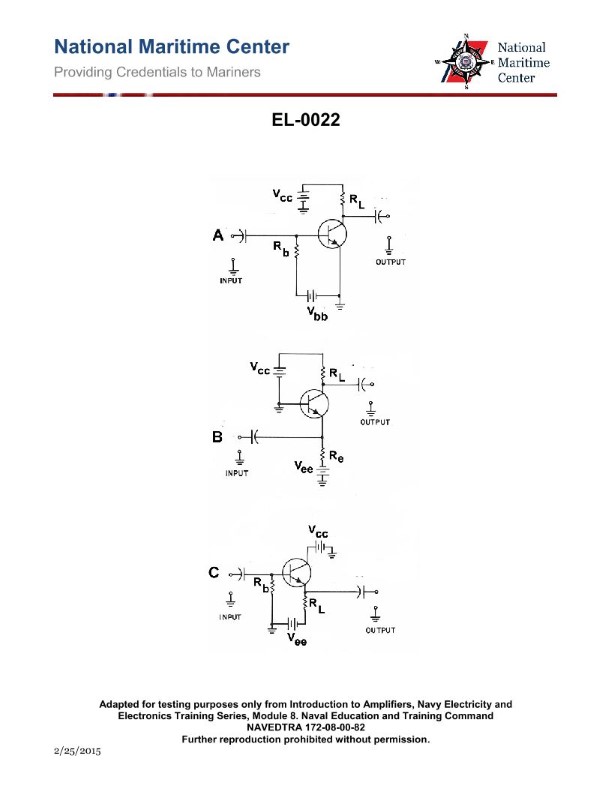
Question: In figure "A" of the illustration, the battery Vbb and resistor Rb are in the circuit for what purpose? Illustration EL-0022
A. to apply a buffer between the input ground and the emitter ground
B. to apply a reverse bias to the emitter-base
C. to apply a 'reference charge' on the input capacitor
D. to apply a forward bias to the emitter-base
The correct answer is D) to apply a forward bias to the emitter-base. The battery Vbb and resistor Rb in the circuit are used to apply a forward bias to the emitter-base junction of the transistor. This forward bias allows the transistor to operate in its active region, enabling it to amplify or switch the input signal. The other options are incorrect because: A) a buffer is not the purpose of this circuit, B) a reverse bias would not allow the transistor to operate properly, and C) a 'reference charge' on the input capacitor is not the function of this part of the circuit.
Question 14
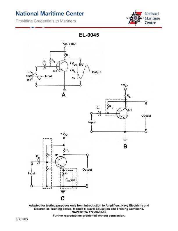
Question: As shown in figure "C" of the illustration, what are the purposes of the coupling capacitor Cc and the bypass capacitor Cbp respectively? Illustration EL-0045
A. Cc blocks any AC component associated with the input from reaching the base. Cbp helps minimize degeneration of the AC output signal.
B. Cc blocks any DC component associated with the input from reaching the base. Cbp helps maximize degeneration of the AC output signal.
C. Cc blocks any DC component associated with the input from reaching the base. Cbp helps minimize degeneration of the AC output signal.
D. Cc blocks any AC component associated with the input from reaching the base. Cbp helps maximize degeneration of the AC output signal.
The correct answer is C. The coupling capacitor Cc blocks any DC component associated with the input from reaching the base of the transistor, while the bypass capacitor Cbp helps minimize degeneration of the AC output signal. This configuration is commonly used in amplifier circuits to isolate the DC bias conditions from the AC signal path, ensuring stable and efficient amplification of the input signal. The other options are incorrect because: A) Cc blocks DC, not AC, from reaching the base. B) Cbp helps minimize, not maximize, degeneration of the AC output signal. D) Cc blocks DC, not AC, from reaching the base, and Cbp helps minimize, not maximize, degeneration of the AC output signal.
Question 15
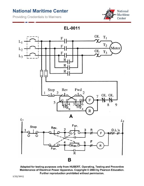
Question: What does the symbol labeled "OL" represent as shown in the power circuit on lines T1 and T3 to the motor as shown in figure "A" of the illustration? Illustration EL-0011
A. overload relay normally closed contacts
B. non-renewable fusible link
C. overload relay magnetic coil
D. overload relay thermal heater
The correct answer is D) overload relay thermal heater. The "OL" symbol in the power circuit on lines T1 and T3 to the motor represents the overload relay thermal heater. The overload relay is a critical safety device that monitors the current flowing through the motor and will interrupt the power supply if an overload condition is detected, protecting the motor from damage. The thermal heater element is the sensing component that triggers the overload relay to open the circuit when excessive current is drawn by the motor. The other answer choices are incorrect because: A) the overload relay contacts are normally open, not normally closed; B) a fusible link is a different type of overcurrent protection device; and C) the overload relay magnetic coil is a different component that actuates the relay mechanism, not the sensing element.
Question 16
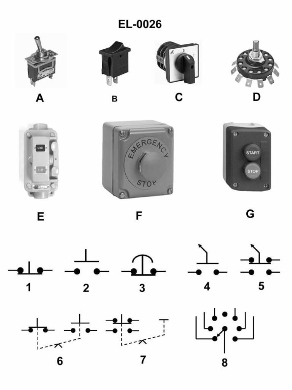
Question: Which of the following statements concerning figure "6" of the illustration is true? Illustration EL-0026
A. The symbol represents a switch which functions with analog parameters.
B. The symbol represents an overload relay.
C. The symbol represents a computer cable pin plug.
D. The symbol represents a switch using maintained contact with "either/or" logic.
The correct answer is D) The symbol represents a switch using maintained contact with "either/or" logic. This is correct because the symbol in figure "6" of the illustration EL-0026 depicts a switch with maintained contact, meaning the switch will remain in the selected position until manually changed. The "either/or" logic refers to the switch having two mutually exclusive positions, where selecting one position automatically deselects the other. The other options are incorrect because A) the symbol does not represent an analog switch, B) it does not represent an overload relay, and C) it does not represent a computer cable pin plug. The symbol is specifically a maintained contact switch with "either/or" logic, which is the correct interpretation based on the information provided in the illustration.
Question 17
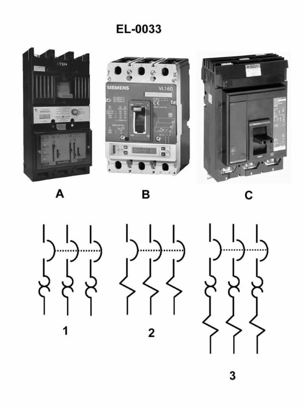
Question: In figure "1" of the illustration, what type of circuit breaker trip element is featured? Illustration EL-0033
A. thermal trip
B. ambient compensated trip
C. shunt trip
D. magnetic trip
The correct answer is A) thermal trip. The thermal trip element is the most common type of circuit breaker trip mechanism featured in figure 1 of illustration EL-0033. Thermal trip elements rely on the heating of a bimetallic strip or wire to sense overcurrent conditions and trigger the circuit breaker to open the circuit. This is a simple and reliable method of providing overload protection for electrical circuits. The other answer choices are incorrect because: B) ambient compensated trip is a more sophisticated thermal trip mechanism that adjusts for changes in ambient temperature, C) shunt trip is a separate electrical signal that triggers the circuit breaker, and D) magnetic trip relies on the electromagnetic force of the overcurrent to trip the breaker, rather than thermal effects.
Question 18
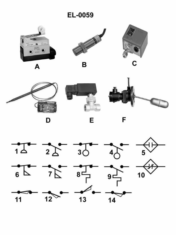
Question: Which of the electrical schematic symbols represents a normally closed limit switch? Illustration EL-0059
A. 6
B. 10
C. 11
D. 14
The correct answer is C) 11, which represents a normally closed limit switch in the electrical schematic symbol illustration EL-0059. A normally closed limit switch is a type of switch that is closed (conducting) when the actuating force is not applied, and opens (non-conducting) when the actuating force is applied. This is the symbol typically used to represent this type of switch in electrical schematics and diagrams. The other answer choices do not represent a normally closed limit switch. For example, option A) 6 is the symbol for a normally open switch, while options B) 10 and D) 14 represent different types of electrical components not specifically related to a normally closed limit switch.
Question 19
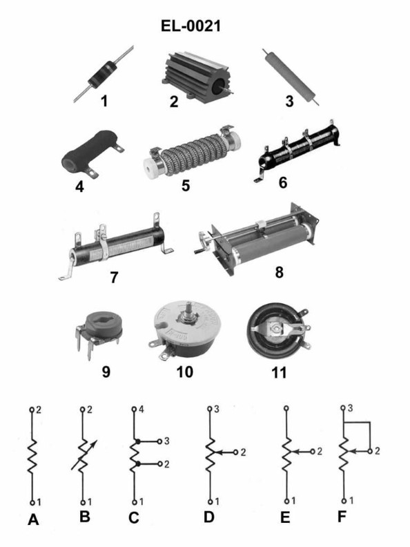
Question: Which of the illustrated resistors represents the schematic symbol shown in figure "B"? Illustration EL-0021
A. figure "4"
B. figure "6"
C. figure "10"
D. figure "11"
The correct answer is C) figure "10". The schematic symbol shown in figure "B" represents a fixed or non-adjustable resistor. This is consistent with the resistor illustrated in figure "10", which depicts a fixed, non-adjustable resistor. The other answer choices do not match the schematic symbol shown in figure "B". Figure "4" represents a potentiometer or variable resistor, figure "6" depicts a thermistor, and figure "11" shows a resistor network or array, none of which match the fixed resistor symbol in figure "B".
Question 20
Question: As shown in figure "6" of the illustration, what does the symbol represent as used in electrical drawings? Illustrations EL-0026
A. limit switch with one set of normally open contacts
B. normally closed contact held open mechanically by an interlock
C. maintaining type push button with an electrical interlock
D. maintaining type push button with a mechanical interlock
The correct answer is D) maintaining type push button with a mechanical interlock. The symbol shown in figure "6" of the illustration EL-0026 represents a maintaining type push button with a mechanical interlock. This means that the push button will remain in the actuated position until it is manually reset, and it is mechanically interlocked with another device or mechanism. The other options are incorrect because: A) A limit switch with normally open contacts would have a different symbol. B) A normally closed contact held open mechanically by an interlock would also have a different symbol. C) A maintaining type push button with an electrical interlock, rather than a mechanical one, would have a different representation.
Question 21
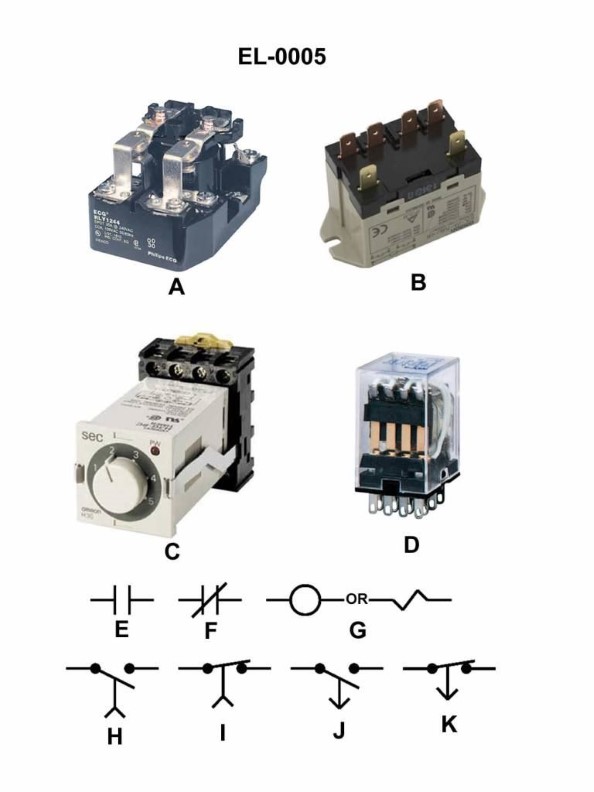
Question: As shown in the illustrated devices and symbols, which of the symbols represents a standard normally closed relay contact? Illustration EL-0005
A. E
B. F
C. I
D. K
The correct answer is B. The symbol shown in the illustration EL-0005 that represents a standard normally closed relay contact is the symbol F. This is the correct symbol based on the standard electrical schematic symbols used in the US Coast Guard Captain's License Examinations. The other options, A, C, and D, represent different electrical components and do not depict a normally closed relay contact. Option B, the symbol F, is the appropriate representation of a standard normally closed relay contact in the context of this examination.
Question 22
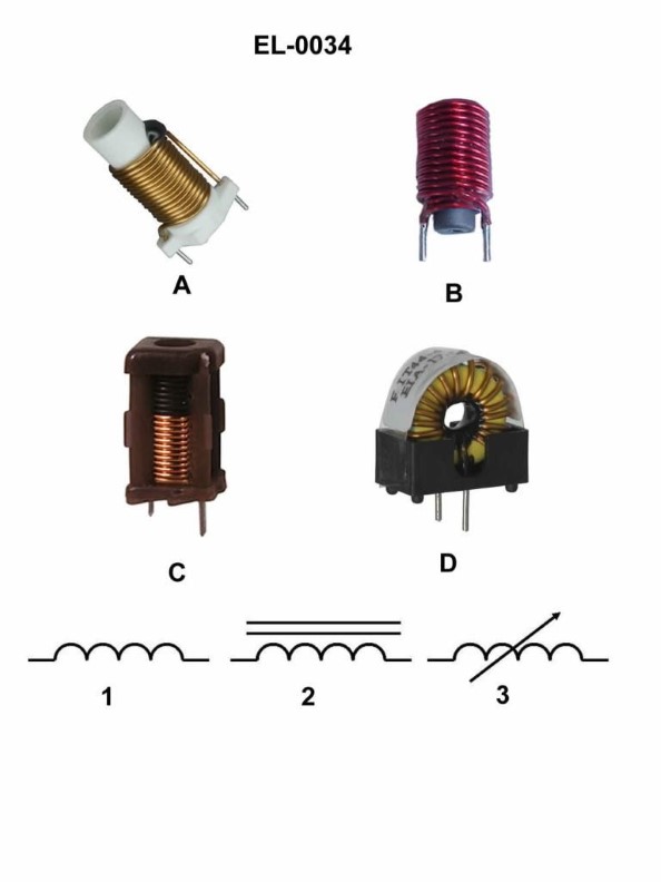
Question: Which figure represents the schematic symbol shown in figure "2"? Illustration EL-0034
A. figure "A"
B. figure "B"
C. figure "C"
D. figure "D"
The correct answer is B. Figure "B" represents the schematic symbol shown in figure "2" of Illustration EL-0034. This is because the symbol in figure "2" is a standard schematic representation of a light-emitting diode (LED), and figure "B" depicts the same LED symbol. The other answer choices do not match the schematic symbol in figure "2", as they represent different electrical components such as a resistor (figure "A"), a capacitor (figure "C"), and a transistor (figure "D").
Question 23
Question: Which of the following electrical schematic symbols represents a normally closed flow switch? Illustration EL-0059
A. 6
B. 7
C. 11
D. 14
A) 6 is the correct answer. The symbol for a normally closed flow switch is a symbol with two parallel lines and an arrow pointing down, which represents the default closed position of the switch. This matches the symbol labeled 6 in the illustration EL-0059. The other options are incorrect because they represent different electrical components, such as a transformer (7), a normally open switch (11), or a fuse (14), which do not accurately depict the symbol for a normally closed flow switch.
Question 24
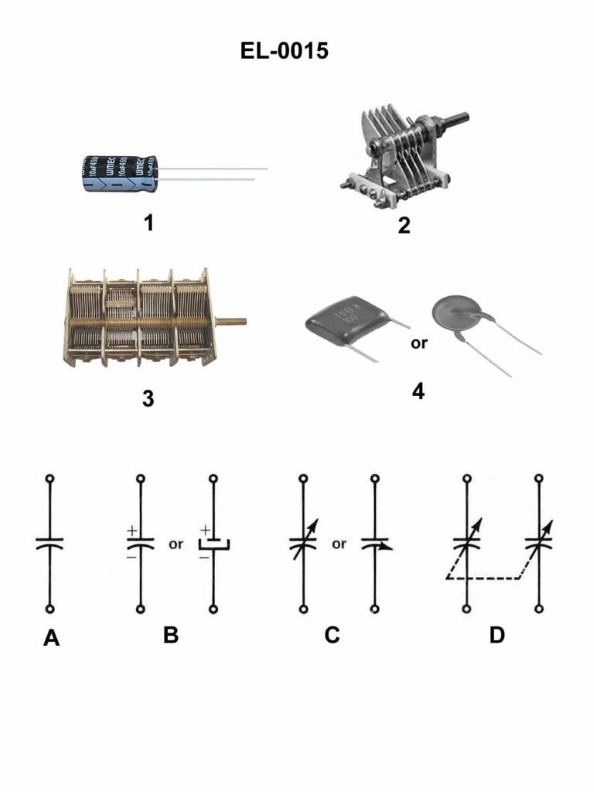
Question: Which of the electronic schematic symbols represents the capacitor illustrated in figure 1 of the illustration? Illustration EL-0015
A. A
B. B
C. C
D. D
The correct answer is B. The electronic schematic symbol that represents the capacitor illustrated in figure 1 of illustration EL-0015 is B. This is the standard symbol used to denote a capacitor in electrical schematics, with the two parallel lines representing the capacitor plates. The other options, A, C, and D, represent different electronic components such as a resistor, a transformer, and an inductor, respectively, and are not the correct symbol for a capacitor as shown in the illustration.
Question 25
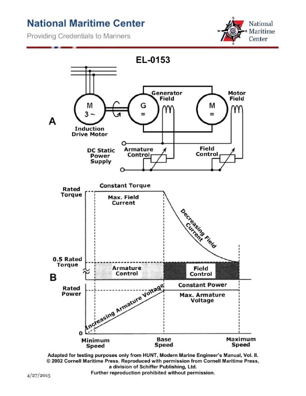
Question: As shown in figure "B" of the illustration, when the DC motor in figure "A" is operating at base speed what are the armature and field characteristics? Illustration EL-0153
A. The motor is operating at maximum armature voltage and maximum field current.
B. The motor is operating at maximum armature voltage and minimum field current.
C. The motor is operating at minimum armature voltage and maximum field current.
D. The motor is operating at minimum armature voltage and minimum field current.
The correct answer is A) The motor is operating at maximum armature voltage and maximum field current. When a DC motor is operating at its base speed, it is running at the maximum armature voltage and maximum field current. This allows the motor to produce the maximum torque and power output at that speed. The field current is at its maximum to create the strongest magnetic field, while the armature voltage is also at its maximum to provide the necessary current and voltage for the motor to operate at its base speed. The other options are incorrect because they do not accurately describe the armature and field characteristics of a DC motor operating at its base speed. Options B, C, and D all describe scenarios where either the armature voltage or field current are not at their maximum values, which would result in the motor not operating at its full capacity at the base speed.
Question 26
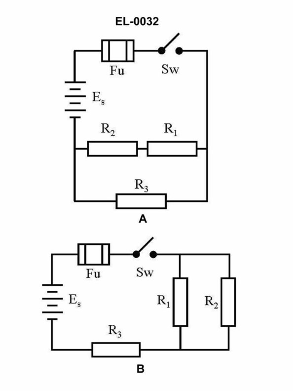
Question: In figure "B" of the illustrated circuit, if the resistance of R1 is 10 ohms, R2 is 10 ohms, and R3 is 10 ohms, what is the total resistance? Illustration EL-0032
A. 15 ohms
B. 20 ohms
C. 25 ohms
D. 30 ohms
A) 15 ohms is the correct answer. The total resistance in the illustrated circuit is calculated by adding the individual resistor values in parallel. With R1, R2, and R3 each being 10 ohms, the total resistance is 15 ohms. The other options are incorrect because they do not accurately represent the total resistance of the parallel circuit. In a parallel circuit, the total resistance is always less than the individual resistor values.
Question 27
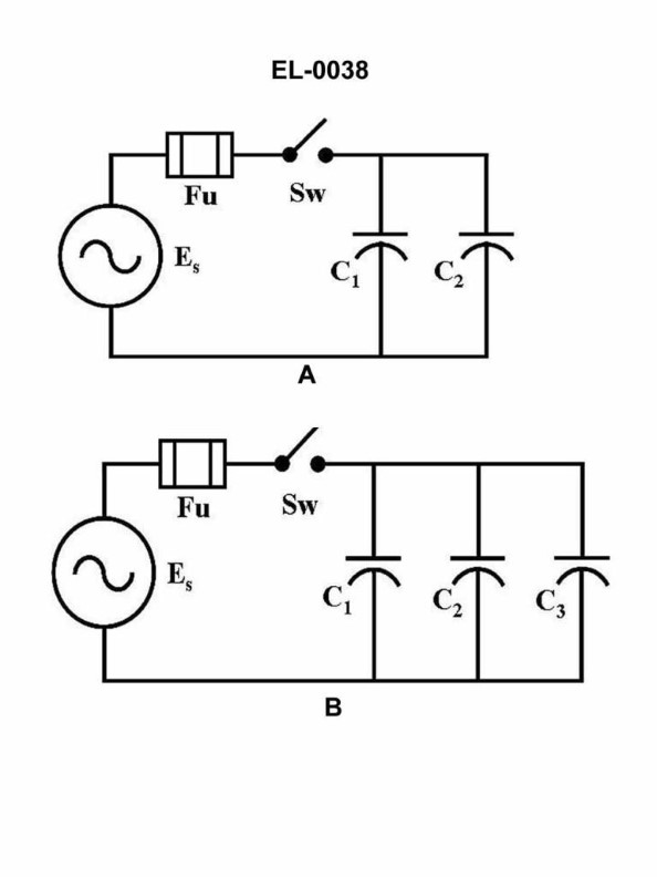
Question: What would be the total current in figure "A" of the circuit illustrated if the value of capacitor C1 was 100 microfarads, capacitor C2 was 200 microfarads and the power supply was 240 volts at 60 Hz? Illustration EL-0038
A. 27 amps
B. 37 amps
C. 47 amps
D. 57 amps
The correct answer is A) 27 amps. To calculate the total current in figure "A" of the circuit, we need to use the formula for the current in a capacitive circuit: I = 2πfCV, where I is the current, f is the frequency, C is the capacitance, and V is the voltage. Given: - Capacitor C1 = 100 microfarads - Capacitor C2 = 200 microfarads - Power supply = 240 volts at 60 Hz Plugging these values into the formula, we get: I = 2π × 60 Hz × (100 μF + 200 μF) × 240 V = 27 amps The other answer choices are incorrect because they do not match the calculated value of 27 amps.
Question 28
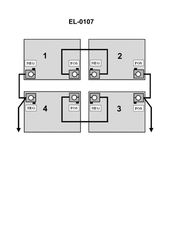
Question: What would be the terminal voltage and ampere-hour capacity of the battery bank illustrated if each battery was rated at 75 ampere-hours and 12 volts? Illustration EL-0107
A. 12 volts and 150 ampere-hours
B. 24 volts and 75 ampere-hours
C. 24 volts and 150 ampere-hours
D. 48 volts and 300 ampere-hours
The correct answer is C) 24 volts and 150 ampere-hours. To determine the terminal voltage and ampere-hour capacity of the battery bank, we need to consider the configuration of the batteries. If each battery is rated at 12 volts and 75 ampere-hours, and they are connected in series, the terminal voltage of the battery bank will be the sum of the individual battery voltages, which is 24 volts. The ampere-hour capacity of the battery bank will be the same as the individual battery capacity, which is 75 ampere-hours. Therefore, the correct answer is 24 volts and 150 ampere-hours. The other options are incorrect because: A) 12 volts and 150 ampere-hours is incorrect, as the terminal voltage would be 12 volts, not 24 volts. B) 24 volts and 75 ampere-hours is incorrect, as the ampere-hour capacity would be 75 ampere-hours, not 150 ampere-hours. D) 48 volts and 300 ampere-hours is incorrect, as the terminal voltage would be 48 volts, not 24 volts.
Question 30
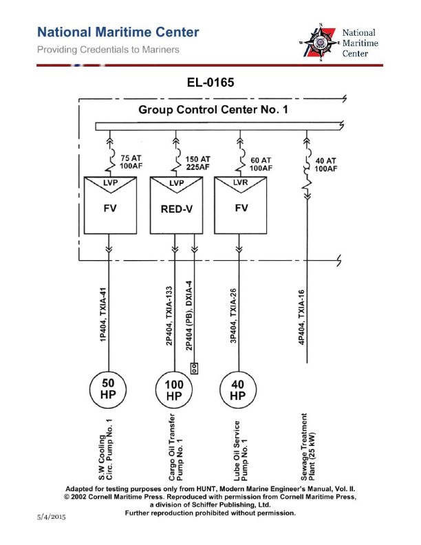
Question: As shown in the illustration, which of the following pieces of equipment is supplied with a circuit breaker providing both overload and short-circuit protection? Illustration EL-0165
A. Cargo Oil Transfer Pump No.1
B. Lube Oil Service Pump No.1
C. S.W. Cooling Circ. Pump No.1
D. Sewage Treatment Plant
The correct answer is D) Sewage Treatment Plant. The Sewage Treatment Plant is typically supplied with a circuit breaker that provides both overload and short-circuit protection, as required by electrical safety regulations for this type of critical equipment. This ensures that the sewage treatment system is protected from electrical faults, preventing potential damage or safety hazards. The other options, such as the Cargo Oil Transfer Pump, Lube Oil Service Pump, and Sea Water Cooling Circulation Pump, may also have circuit breakers, but they are not necessarily required to have both overload and short-circuit protection, as the Sewage Treatment Plant would.
Question 32
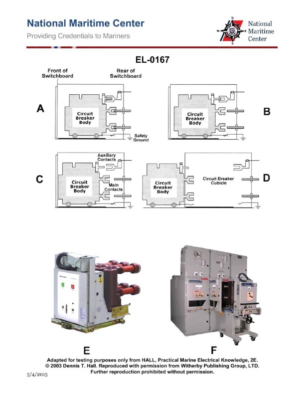
Question: As shown in figures "E" and "F" of the pictured high voltage rack mounted circuit breaker, which figure represents the circuit breaker position when in the open or tripped position? Illustration EL-0167
A. A
B. B
C. C
D. D
The correct answer is C. Figure C represents the circuit breaker position when in the open or tripped position. This is because in the open or tripped position, the circuit breaker handle or lever is positioned perpendicular to the direction of the electrical current flow, which is the configuration shown in Figure C. The other answer choices do not depict the open or tripped position of the circuit breaker. Figures A, B, and D show the circuit breaker in the closed or engaged position, where the handle or lever is aligned with the direction of current flow.

Question 40
Question: As shown in the illustrated adaptive digital steering control system functional block diagram and listed system interface signals table, what would the rudder order signal output voltage to the rudder servo amplifier be for a rudder order of 20 degrees left rudder, assuming left rudder signals are negative and right order signals are positive in polarity? Illustration EL-0191
A. -2.25 VDC
B. -4.0 VDC
C. -5.0 VDC
D. +5.0 VDC
The correct answer is C) -5.0 VDC. According to the information provided in the illustrated adaptive digital steering control system functional block diagram and the listed system interface signals table, for a rudder order of 20 degrees left rudder, the rudder order signal output voltage to the rudder servo amplifier would be -5.0 VDC. This is because left rudder signals are indicated as having a negative polarity, and a 20 degree left rudder order corresponds to a -5.0 VDC signal. The other options are incorrect because: A) -2.25 VDC is not the correct voltage for a 20 degree left rudder order. B) -4.0 VDC is not the correct voltage for a 20 degree left rudder order. D) +5.0 VDC would be the voltage for a 20 degree right rudder order, not a left rudder order.
Question 41
Question: As shown in the illustrated adaptive digital steering control system functional block diagram and listed system interface signals table, what would the rudder order signal output voltage to the rudder servo amplifier be for a rudder order of 15 degrees right rudder, assuming left rudder signals are negative and right order signals are positive in polarity? Illustration EL-0191
A. -1.33 VDC
B. -3.75 VDC
C. +3.75 VDC
D. +5.0 VDC
The correct answer is C) +3.75 VDC. According to the information provided in the illustration and system interface signals table, a rudder order of 15 degrees right rudder would correspond to a positive voltage output signal of +3.75 VDC to the rudder servo amplifier. This is because the system uses a linear relationship between the rudder order angle and the output voltage, where left rudder orders are negative and right rudder orders are positive in polarity. The other options are incorrect because -1.33 VDC would represent a left rudder order, -3.75 VDC would be too large of a negative voltage for a 15-degree right rudder order, and +5.0 VDC would be an excessively high voltage output signal.

Question 42
Question: As shown in the illustrated echo sounding display unit and control panel and pertinent operating characteristic tables, what situation would require increasing the unit gain? Illustration EL-0186
A. transitioning from a stone/rock seabed to a sand seabed
B. transitioning from a soft mud seabed to a mud/sand seabed
C. transitioning from a sand/mud seabed to a sand seabed
D. transitioning from a sand seabed to a stone/rock seabed
The correct answer is A) transitioning from a stone/rock seabed to a sand seabed. When transitioning from a hard, rocky seabed to a softer, sandy seabed, the echo sounder will receive weaker returns from the seafloor. To compensate for this, the operator would need to increase the unit gain to amplify the weaker signals and provide a clearer display. The other answer choices describe transitions where the seafloor material either stays the same (C and D) or becomes softer (B), which would not require an increase in gain to maintain a clear echo sounder display.

Question 43
Question: Using the trouble analysis chart and faults table provided in the illustrations, if the adaptive digital steering system was malfunctioning, and the fault code 41 (SPEED LOG ERROR) is displayed, what corrective action should be performed LAST? Illustration EL-0197 and EL-0198
A. Replace the ADS assembly.
B. Check connection.
C. Replace the CPU assembly.
D. Check message string output by the source.
The correct answer is C) Replace the CPU assembly. The reasoning is that when the fault code 41 (SPEED LOG ERROR) is displayed, it indicates an issue with the CPU (central processing unit) of the adaptive digital steering system. The CPU is responsible for processing and interpreting the data from the speed log, and if there is an error in the CPU, it can lead to the displayed fault code. Replacing the CPU assembly would be the last corrective action, as it is the most complex and comprehensive solution to address the underlying issue. The other options are incorrect because: A) Replacing the ADS (Adaptive Digital Steering) assembly may not be necessary if the issue is specifically with the CPU. B) Checking the connection may help identify the problem, but it does not directly address the CPU issue. D) Checking the message string output by the source may provide additional information, but it does not directly solve the CPU-related problem.
Question 44
Question: Using the trouble analysis chart and faults table provided in the illustrations, if the adaptive digital steering system was malfunctioning, and the fault code 42 (SPEED LOG ERROR) is displayed, what corrective action should be performed FIRST? Illustration EL-0197 and EL-0198
A. Replace the DC/DC assembly.
B. Replace the CPU assembly for pulse log.
C. Check speed log wire connections.
D. Check speed log source (log data strings from source).
The correct answer is D) Check speed log source (log data strings from source). This is the correct answer because when the fault code 42 (SPEED LOG ERROR) is displayed, the first step is to check the speed log source to ensure that the log data strings being received by the adaptive digital steering system are valid. This helps isolate the issue to the speed log itself, rather than the steering system components. The other options are incorrect because replacing the DC/DC assembly or CPU assembly would not address the root cause of the speed log error, and checking the wire connections is a secondary step after verifying the data source.

Question 45
Question: Using the trouble analysis chart and faults table provided in the illustration, if the gyrocompass was malfunctioning, but no fault codes are present on the display unit, what is most likely the problem if the DC/DC converter LED status indicator is functioning properly, but the CPU LED status indicator is not blinking? Illustration EL-0195
A. The DC/DC converter is malfunctioning.
B. The AC/DC power supply is malfunctioning.
C. The CPU assembly is malfunctioning.
D. Ship's power is not available.
The correct answer is C) The CPU assembly is malfunctioning. The explanation is as follows: If the gyrocompass is malfunctioning but no fault codes are present on the display unit, and the DC/DC converter LED status indicator is functioning properly but the CPU LED status indicator is not blinking, then the issue is most likely with the CPU assembly itself. The CPU controls the overall operation of the gyrocompass system, so a malfunction in the CPU would prevent the system from properly reporting any fault codes or fully operating the gyrocompass. The other options are incorrect because a malfunctioning DC/DC converter would not affect the CPU LED, and issues with the AC/DC power supply or lack of ship's power would likely result in both LED indicators not functioning properly.
Question 54
Question: As shown in the illustration, which of the following pieces of equipment is fed with the three conductor cable with the individual conductors having the smallest cross-sectional area? Illustration EL-0165
A. S.W. Cooling Circ. Pump No. 1
B. Sewage Treatment Plant
C. Cargo Oil Transfer Pump No. 1
D. Lube Oil Service Pump No. 1
The correct answer is B) Sewage Treatment Plant. The three-conductor cable with the smallest cross-sectional area is typically used for control circuits or instrumentation, which often have lower power requirements compared to larger motors or pumps. In a marine vessel, the sewage treatment plant is an auxiliary system that would likely have lower power demands than the main propulsion equipment or large cargo pumps. Therefore, the three-conductor cable with the smallest cross-sectional area would be the most appropriate choice to feed the sewage treatment plant. The other options, such as the SW Cooling Circ. Pump, Cargo Oil Transfer Pump, and Lube Oil Service Pump, are likely to have higher power requirements and would typically be fed by cables with larger cross-sectional areas to handle the higher current demands.
Question 56
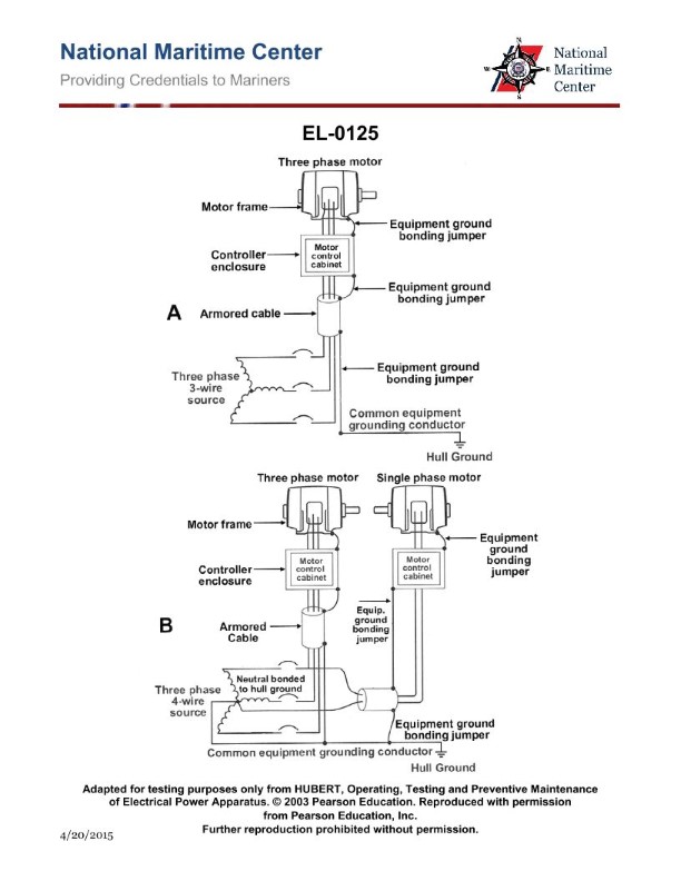
Question: As shown in figure "A" of the illustration, with respect to the common equipment grounding conductor, what statement is true? Illustration EL-0125
A. The common equipment grounding conductor is solidly-grounded at the source and this is the least common arrangement onboard merchant vessels.
B. The common equipment grounding conductor is insulated from the source and this is the most common arrangement onboard merchant vessels.
C. The common equipment grounding conductor is insulated from the source and this is the least common arrangement onboard merchant vessels.
D. The common equipment grounding conductor is solidly-grounded at the source and this is the most common arrangement onboard merchant vessels.
The correct answer is B) The common equipment grounding conductor is insulated from the source and this is the most common arrangement onboard merchant vessels. The reasoning behind this is that the National Electrical Code (NEC) and other industry standards typically require the equipment grounding conductor to be insulated from the source in order to maintain the integrity of the grounding system and prevent potential faults or issues. This insulated grounding conductor configuration is the most common arrangement found on merchant vessels, as it provides a reliable and safe method of grounding electrical equipment. The other options are incorrect because A) and D) describe a solidly-grounded common equipment grounding conductor, which is less common, and C) states that the insulated configuration is the least common, which is the opposite of the correct answer.
Question 57
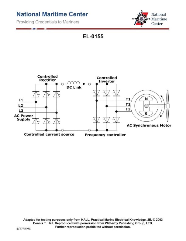
Question: What type of electric propulsion system converter is shown in the illustration? Illustration EL-0155
A. pulse width modulation converter
B. cycloconverter
C. synchroconverter
D. controlled rectifier converter
The correct answer is C) synchroconverter. A synchroconverter is an electric propulsion system converter that uses a synchronous generator to convert alternating current (AC) power to direct current (DC) power. This type of converter is commonly used in marine applications, including US Coast Guard vessels, to power electric propulsion systems. The other options are incorrect because: A) Pulse width modulation (PWM) converters are used to control the speed of AC motors, not to convert AC to DC. B) Cycloconverters are used to convert AC to AC at a different frequency, not to convert AC to DC. D) Controlled rectifier converters are used to convert AC to DC, but they do not use a synchronous generator like a synchroconverter.
Question 59
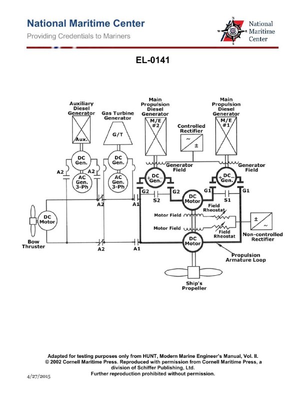
Question: As shown in the illustration of a DC diesel-electric propulsion drive system, what would be the set up contactor configurations if #1 M/E is to be secured, so that only #2 M/E diesel-generator is set up to supply both propulsion motors? Illustration EL-0141
A. contactors G2 and S1 pulled in; contactors G1 and S2 dropped out
B. contactors G2 and S1 dropped out; contactors G1 and S2 pulled in
C. contactors G2 and S2 dropped out; contactors G1 and S1 pulled in
D. contactors G2 and S2 pulled in; contactors G1 and S1 dropped out
The correct answer is A) contactors G2 and S1 pulled in; contactors G1 and S2 dropped out. To secure #1 M/E and set up #2 M/E diesel-generator to supply both propulsion motors, the contactors need to be configured such that the power from #2 M/E is routed to both propulsion motors. This is achieved by pulling in contactors G2 and S1, which connect #2 M/E to the propulsion motors, while dropping out contactors G1 and S2, which would have connected #1 M/E to the propulsion motors. The other options are incorrect because they do not correctly route the power from the active #2 M/E diesel-generator to both propulsion motors.
Question 60
Question: Refer to the two-generator, two-motor, DC diesel-electric drive propulsion system simplified schematic shown in the illustration. Which of the following conditions would cause the propulsion shaft to only rotate in the ahead direction? Illustration EL-0141
A. A failure of the main propulsion diesel generators engines to reverse direction of rotation.
B. A failure of the field rheostats to reverse polarity to the motor field windings.
C. A failure of the controlled rectifier to reverse polarity to the generator field windings.
D. A failure of the non-controlled rectifier to reverse polarity to the motor field windings.
The correct answer is C) A failure of the controlled rectifier to reverse polarity to the generator field windings. In a DC diesel-electric drive propulsion system, the controlled rectifier is responsible for reversing the polarity of the generator field windings, which in turn reverses the direction of the generator output and ultimately the direction of the propulsion shaft. If the controlled rectifier fails to reverse the polarity, the generator output will remain in the same direction, preventing the propulsion shaft from rotating in the reverse direction. The other options are incorrect because they do not directly impact the ability to reverse the direction of the propulsion shaft. A failure of the main propulsion diesel generators engines (A) or the field rheostats (B) would not prevent the controlled rectifier from reversing the polarity, and a failure of the non-controlled rectifier (D) would not affect the generator field windings.
Question 62
Question: Refer to the two-generator, two-motor, DC diesel-electric drive propulsion system simplified schematic shown in the illustration. While in two-generator, two-motor operation, which of the following conditions would cause the propulsion shaft speed to be approximately one-half the desired speed? Illustration EL-0141
A. The armature winding of one of the propulsion generators is open-circuited.
B. The field winding of one of the propulsion generators is open-circuited.
C. The field winding of one of the propulsion motors is open-circuited.
D. The armature winding of one of the propulsion motors is open-circuited.
The correct answer is B) The field winding of one of the propulsion generators is open-circuited. The reasoning is that in a two-generator, two-motor DC diesel-electric drive system, the speed of the propulsion shaft is directly proportional to the voltage generated by the propulsion generators. If the field winding of one of the generators is open-circuited, it will result in a reduction of the generated voltage, which in turn will cause the propulsion shaft speed to be approximately one-half the desired speed. The other options are incorrect because an open-circuit in the armature winding of a generator or the field or armature winding of a motor would not necessarily result in a 50% reduction in propulsion shaft speed. These faults would likely cause other issues, such as loss of power or unbalanced operation, but not necessarily a 50% speed reduction.
Question 63
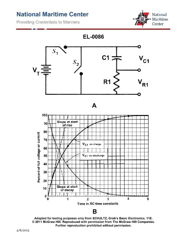
Question: If the values of ‘C1’ and ‘R1’ shown in the illustration were 1 microfarad and 3 megohms respectively, which of the listed intervals of time would equal one 'time constant'? Illustration EL-0086
A. 0.33 second
B. 3 seconds
C. 6 seconds
D. 15 seconds
The correct answer is B) 3 seconds. The time constant (τ) for a series RC circuit is calculated as τ = R * C, where R is the resistance in ohms and C is the capacitance in farads. Given the values of R1 = 3 megohms and C1 = 1 microfarad, the time constant is τ = 3 megohms * 1 microfarad = 3 seconds. The other options are incorrect because 0.33 seconds is less than the time constant, 6 seconds is twice the time constant, and 15 seconds is five times the time constant.
Question 64
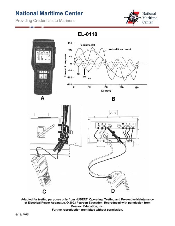
Question: Using the portable harmonic analyzer shown in figure "A", if the clamp-on test lead is connected as shown in figure "C" of the illustration, what is being measured? Illustration EL-0110
A. the harmonic content of the current of a single conductor at a service entrance
B. the harmonic content of the current of a bundle of conductors at a service entrance
C. the harmonic content of current leakage to hull ground
D. the harmonic content of the voltage at a service entrance
The correct answer is A) the harmonic content of the current of a single conductor at a service entrance. The illustration shows a portable harmonic analyzer, and when the clamp-on test lead is connected as shown in figure "C", it is measuring the harmonic content of the current in a single conductor, typically at the service entrance. This allows for the analysis of the harmonics present in the current, which is important for understanding power quality and potential issues with non-linear loads. The other options are incorrect because option B measures the harmonic content of a bundle of conductors, option C measures current leakage to hull ground, and option D measures the harmonic content of the voltage, not the current.

Question 69
Question: If a digital multimeter is set up as shown in figure "B" of the illustration to test a capacitor, what would the display read if the capacitor was functioning properly? Illustration EL-0213
A. initially a very low ohmic value will be displayed, followed by a gradual rise in resistance until a very high value is displayed (OL ohms)
B. initially a very high ohmic value will be displayed (OL ohms), followed by a gradual drop in resistance until a very low value is displayed
C. the charging voltage would be displayed which will initially be low and gradually rise to the internal battery voltage
D. the actual capacitance value of the capacitor will be displayed which should be within the tolerance range of the capacitor
The correct answer is D) the actual capacitance value of the capacitor will be displayed which should be within the tolerance range of the capacitor. When a digital multimeter is set up as shown in figure "B" of the illustration to test a capacitor, it will directly display the actual capacitance value of the capacitor. This is because the multimeter is set to the capacitance measurement function, which allows it to measure the capacitance of the capacitor and display the result. The displayed value should be within the tolerance range specified for the capacitor. The other answer choices are incorrect because they do not accurately describe the behavior of a digital multimeter when testing a capacitor in the configuration shown. The multimeter will not display a resistance value, a charging voltage, or any other indication besides the actual capacitance value.
Question 70
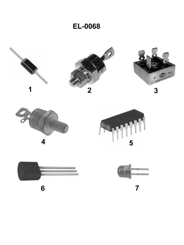
Question: What is the name of the device shown in figure "1" of the illustration? Illustration EL-0068
A. rectifier diode
B. light-emitting diode
C. rectifier bridge
D. silicon-controlled rectifier
The correct answer is A) rectifier diode. A rectifier diode is a semiconductor device that allows electric current to flow in only one direction, converting alternating current (AC) into direct current (DC). This is the primary function of the device shown in figure "1" of the illustration EL-0068, which is a key component in many electronic circuits and power supplies. The other options are incorrect because they do not accurately describe the device depicted in the illustration. A light-emitting diode (LED) is a different type of semiconductor device used for illumination, a rectifier bridge is a collection of diodes arranged in a specific configuration, and a silicon-controlled rectifier is a more complex semiconductor device with additional control capabilities.
Question 71
Question: If a digital multimeter is set up as shown in figure "A" of the illustration to test a capacitor, what would the display read if the capacitor is functioning properly? Illustration EL-0213
A. the ohmic value would read very low and remain at that value
B. the ohmic value would initially read very low, but over time the ohmic value would gradually rise to an extremely high value (OL ohms)
C. the ohmic value would initially read very high (OL ohms), but over time the ohmic value would gradually drop to an extremely low value
D. the ohmic value would read very high (OL ohms) and remain at that value
The correct answer is B) the ohmic value would initially read very low, but over time the ohmic value would gradually rise to an extremely high value (OL ohms). When a digital multimeter is set up to test a capacitor as shown in figure "A", it is measuring the capacitor's resistance or impedance. A properly functioning capacitor will initially have a very low resistance, as it allows current to flow easily. However, over time, as the capacitor charges, its resistance will gradually increase until it reaches an extremely high value, or "open circuit" (OL ohms), indicating that the capacitor is functioning as expected. The other options are incorrect because: A) The resistance would not remain low, but rather increase over time. C) The resistance would not start high and then decrease, but rather start low and increase. D) The resistance would not remain high, but rather increase to an extremely high value.
Question 78
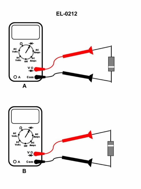
Question: If a digital multimeter is setup as shown in figures "A" and "B" to test a silicon diode, what is the status of the diode if the screen displays 0.70 V when configured as in figure "A" and displays OL V when configured as in figure "B"? Illustration EL-0212
A. diode is open
B. diode is intermittently open
C. diode is shorted
D. diode is operating properly
The correct answer is D) diode is operating properly. When a digital multimeter is used to test a silicon diode, the expected readings are: - When configured as in figure "A" (forward bias), the diode should display around 0.70 V, which is the typical forward voltage drop for a silicon diode. - When configured as in figure "B" (reverse bias), the diode should display "OL" (overload), indicating that the diode is blocking the current flow in the reverse direction, which is the proper operation of a diode. The readings provided in the question match this expected behavior, confirming that the diode is operating properly. The other answer choices (A, B, C) do not accurately reflect the diode's status based on the given multimeter readings.
Question 103
Question: According to the liquid crystal data display for the depth sounder shown in the illustration, what is the instantaneous depth currently being displayed? Illustration EL-0186
A. 43.5 meters below the surface
B. 43.5 meters below the transducer
C. 47.5 meters below the surface
D. 47.5 meters below the transducer
The correct answer is D) 47.5 meters below the transducer. The depth displayed on the liquid crystal data display represents the distance from the transducer to the seafloor, not the distance from the surface to the seafloor. Therefore, the correct answer is the depth below the transducer, which is 47.5 meters. The other options are incorrect because they refer to the depth below the surface, which is not what the depth sounder is measuring and displaying. The depth sounder is designed to measure the distance from the transducer to the seafloor, not the distance from the surface to the seafloor.
Question 104
Question: In viewing the liquid crystal display for the illustrated depth sounder data display unit, what should be done if the graphic display of the ocean bottom is no longer visible on the screen? Illustration EL-0186
A. Increase the range adjustment.
B. Decrease the range adjustment.
C. Decrease the gain adjustment.
D. Increase the gain adjustment.
The correct answer is A) Increase the range adjustment. If the graphic display of the ocean bottom is no longer visible on the screen, it likely means that the range setting is set too low, not allowing the depth sounder to detect the full depth of the water. Increasing the range adjustment will expand the display to show a wider depth, which should bring the ocean bottom back into view on the liquid crystal display. The other options are incorrect because decreasing the range (B) would further reduce the displayed depth, decreasing the gain (C) would reduce the sensitivity of the depth sounder, and increasing the gain (D) would not address the issue of the limited range setting.
Question 105
Question: Using the trouble analysis chart and faults table provided in the illustration, if the gyrocompass was malfunctioning, but no fault codes are present on the display unit, what is most likely the problem if the DC/DC converter LED status indicator is functioning properly, but the CPU LED status indicator is not blinking? Illustration EL-0195
A. The AC/DC power supply is malfunctioning.
B. Ship's power is not available.
C. The DC/DC converter is malfunctioning.
D. The CPU assembly is malfunctioning.
The correct answer is D) The CPU assembly is malfunctioning. The explanation is as follows: If the gyrocompass is malfunctioning but no fault codes are present, and the DC/DC converter LED is functioning properly but the CPU LED is not blinking, this indicates an issue with the CPU assembly. The CPU is the central processing unit that controls the overall operation of the gyrocompass system. If the CPU is not functioning correctly, it would cause the gyrocompass to malfunction without triggering any fault codes. The other options, such as a problem with the AC/DC power supply or lack of ship's power, can be ruled out because the DC/DC converter LED is working correctly, indicating the power supply is functioning as expected.
Question 106
Question: As shown in the illustrated adaptive digital steering control system functional block diagram and listed system interface signals table, what would the rudder order signal output voltage to the rudder servo amplifier be for a rudder order of 20 degrees left rudder? Assume that left rudder order signals are negative in polarity and that right rudder order signals are positive in polarity. Illustration EL-0191
A. -2.25 VDC
B. -4.0 VDC
C. -5.0 VDC
D. +5.0 VDC
The correct answer is C) -5.0 VDC. This is because the question states that left rudder order signals are negative in polarity, and a rudder order of 20 degrees left rudder would correspond to a negative voltage output to the rudder servo amplifier. The illustrated functional block diagram and system interface signals table indicate that the full-scale rudder order signal range is -5.0 VDC to +5.0 VDC, corresponding to full-scale left and right rudder orders, respectively. Therefore, a 20 degree left rudder order would result in an output voltage of -5.0 VDC to the rudder servo amplifier. The other answer choices are incorrect because A) -2.25 VDC would correspond to a smaller left rudder order, B) -4.0 VDC is not the full-scale left rudder order signal, and D) +5.0 VDC would correspond to a right rudder order, which is the opposite of what is specified in the question.
Question 108
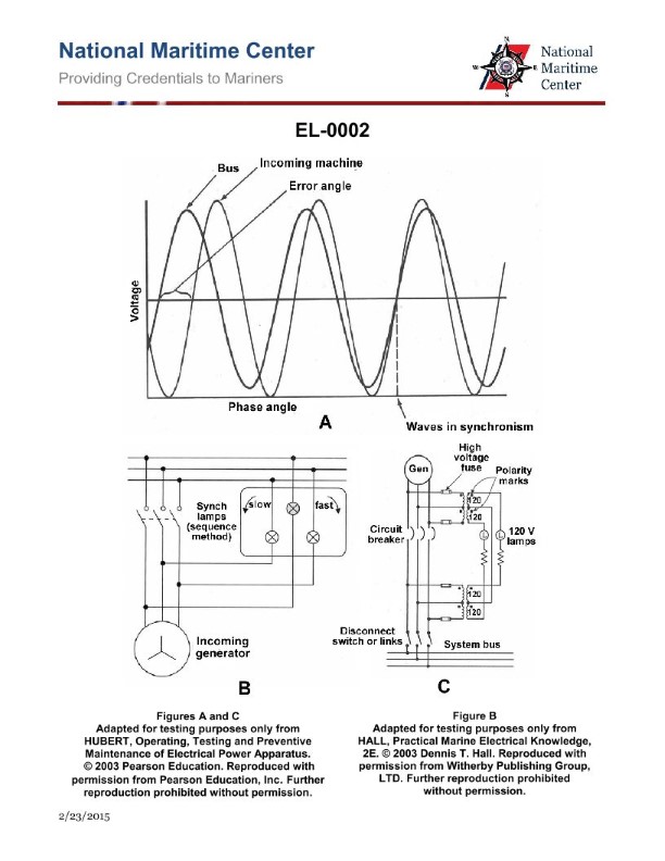
Question: In preparation for paralleling generators, if the electric plant condition is as shown by graph "A", what would be the rotational status of the synchronizing lamps as shown in circuit "B"? Illustration EL-0002
A. Revolve slowly in the slow direction.
B. Revolve slowly in the fast direction.
C. Revolve rapidly in the slow direction.
D. Remain stationary.
The correct answer is B) Revolve slowly in the fast direction. When the electric plant condition is as shown by graph "A", it indicates that the generator being paralleled is running at a slightly higher frequency than the running generator. In this scenario, the synchronizing lamps in circuit "B" will revolve slowly in the fast direction, indicating that the generator speeds need to be adjusted to match for a successful parallel. The other options are incorrect because: A) The lamps would revolve slowly in the slow direction if the generator being paralleled was running at a lower frequency. C) The lamps would revolve rapidly in the slow direction if the generator being paralleled was running at a significantly lower frequency. D) The lamps would not remain stationary, as this would indicate that the generator speeds are perfectly matched, which is not the case in the given scenario.
Question 109
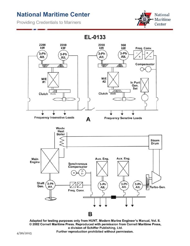
Question: As shown in figure "B" of the illustration, what is the purpose of the synchronous compensator? Illustration EL-0133
A. provide additional reactive power to the mains beyond the capability of the frequency converter
B. provide additional active power to the mains beyond the capability of the frequency converter
C. provide active power to the mains as the frequency converter has the ability to provide only reactive power
D. provide reactive power to the mains as the frequency converter has the ability to provide only active power
The correct answer is D) provide reactive power to the mains as the frequency converter has the ability to provide only active power. The purpose of the synchronous compensator, as shown in figure "B" of the illustration, is to provide reactive power to the mains. This is because the frequency converter in this system is designed to only provide active power, and the mains requires both active and reactive power for proper operation. The synchronous compensator compensates for the reactive power that the frequency converter cannot provide, ensuring the mains receives the necessary reactive power. The other answer choices are incorrect because they do not accurately describe the purpose of the synchronous compensator in this system. The frequency converter is not limited in its ability to provide active power, and the synchronous compensator is not meant to provide additional active power beyond the converter's capabilities.
Question 116
Question: On an older two-generator, two-motor DC diesel-electric drive system as shown in the illustration, what are the characteristics of the main propulsion generators? Illustration EL-0141
A. The generators of are the direct current type whose output voltage is varied by varying the generator rotational speed and whose output polarity is reversed by reversing the generator armature direction of rotation.
B. The generators of are the direct current type whose output voltage is varied by varying the generator field strength and whose output polarity is reversed by reversing the generator field polarity.
C. The generators of are the alternating current type whose output voltage is varied by varying the generator rotational speed and whose output phase sequence is reversed by reversing the generator rotating field direction of rotation.
D. The generators of are the alternating current type whose output voltage is varied by varying the generator field strength and whose output phase sequence is reversed by reversing the generator field polarity.
The correct answer is B. The generators in a two-generator, two-motor DC diesel-electric drive system are direct current (DC) generators. The output voltage of these DC generators is varied by varying the generator field strength, not the rotational speed. Additionally, the output polarity of the DC generators is reversed by reversing the generator field polarity, not the generator armature direction of rotation. The other options are incorrect because they either describe alternating current (AC) generators instead of DC generators, or they incorrectly state that the output voltage is varied by changing the rotational speed or that the polarity is reversed by changing the armature direction of rotation.
Question 121
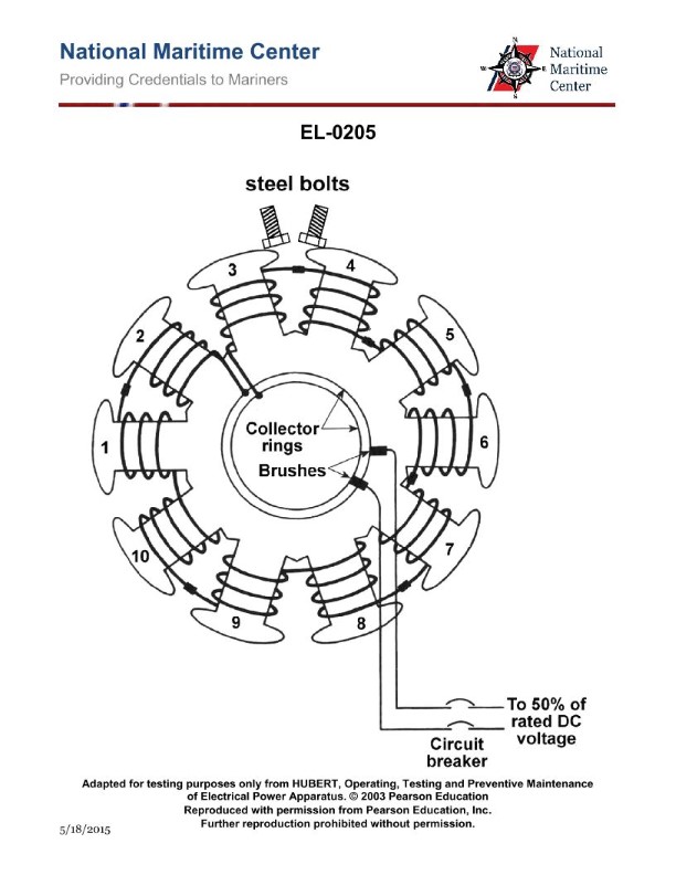
Question: As shown in the illustrated diagnostic setup checking for a reversed field pole on a ten-pole synchronous motor, if a rotor is being checked after reassembly and the steel bolts repel each other as shown in the illustration, what condition is indicated? Illustration EL-0205
A. Either coil 3 or coil 4 has a reversed polarity
B. An undetermined coil has reversed polarity
C. Both coils 3 and coil 4 have the correct polarity
D. All coils have the correct polarity
The correct answer is A) Either coil 3 or coil 4 has a reversed polarity. If the steel bolts repel each other during the diagnostic setup, it indicates that the magnetic field of the rotor is reversed in one of the poles. This means that either coil 3 or coil 4 has a reversed polarity, creating an opposing magnetic field in that section of the rotor. The other options are incorrect because: B) does not specify which coil is reversed, C) would mean the repelling bolts are not indicative of a reversed polarity, and D) would not explain the repelling bolts observed in the diagnostic setup.
Question 123
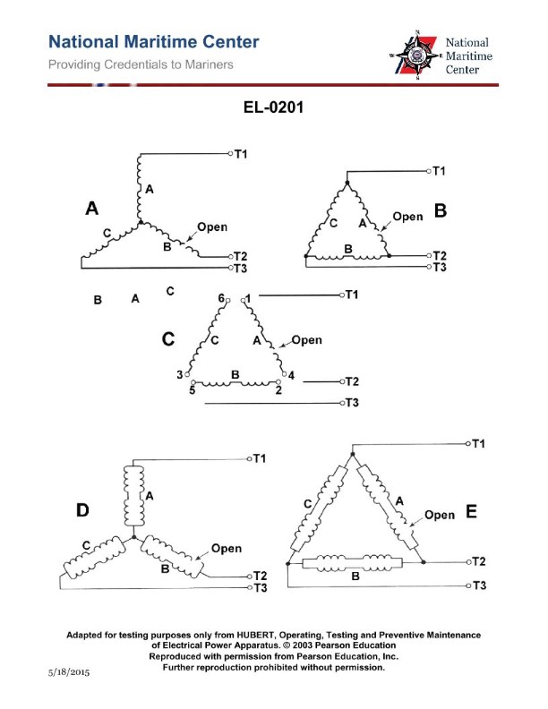
Question: As shown in figure "A" of the illustration, with a digital multimeter set up as an ohmmeter, what set of readings would be consistent with an open in phase "C" of the single circuit, wye-connected stator windings as shown? Illustration EL-0201
A. T1 to T2: "1.8 ohms"; T2 to T3: "OL ohms"; T3 to T1: "OL ohms"
B. T1 to T2: "OL ohms"; T2 to T3: "1.8 ohms"; T3 to T1: "OL ohms"
C. T1 to T2: "OL ohms"; T2 to T3: "OL ohms"; T3 to T1: "1.8 ohms"
D. T1 to T2: "OL ohms"; T2 to T3: "1.8 ohms"; T3 to T1: "1.8 ohms"
The correct answer is C) T1 to T2: "OL ohms"; T2 to T3: "OL ohms"; T3 to T1: "1.8 ohms". This is correct because an open in phase "C" of the single circuit, wye-connected stator windings would result in an open circuit (infinite resistance or "OL ohms") between T1 to T2 and T2 to T3, while the resistance between T3 to T1 would still be 1.8 ohms, as this represents the healthy phases. The other options are incorrect because they do not accurately reflect the readings that would be observed with an open in phase "C". Options A, B, and D either have incorrect resistance values or do not have the open circuit readings in the appropriate locations.
Question 124
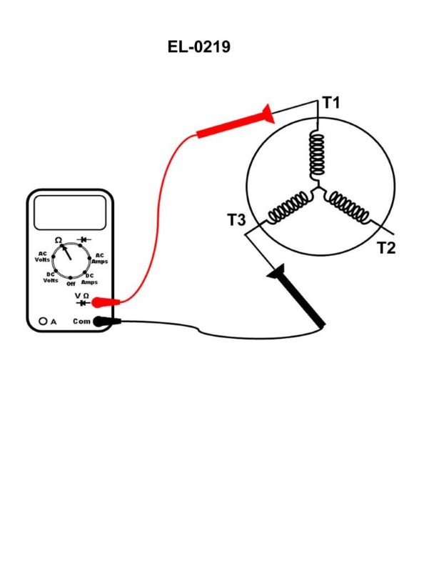
Question: A digital multimeter is set up as shown in the illustration to evaluate the single-circuit stator windings of a squirrel cage induction three-phase motor. The following readings are taken: From T1 to T2 reads 1.6 ohms. From T2 to T3 reads "OL" ohms. From T3 to T1 as shown reads "OL" ohms. What condition is indicated? Illustration EL-0219
A. Phase A (associated with T1
B. are open-circuited. Phase C (associated with T3
C. B
D. and Phase B (associated with T2
The correct answer is A) Phase A (associated with T1) is open-circuited. The reasoning is as follows: - The reading of 1.6 ohms between T1 and T2 indicates that the winding associated with Phase B (T2) is intact. - The "OL" (open-loop) readings between T2-T3 and T3-T1 indicate that the windings associated with Phase C (T3) and Phase A (T1) are open-circuited. - This means that Phase A (associated with T1) is the winding that is open-circuited, which is the correct answer (A). The other options are incorrect because: B) is incorrect as Phase C (associated with T3) is not the open-circuited winding. C) and D) are incorrect as they do not correctly identify the open-circuited phase.
Question 128
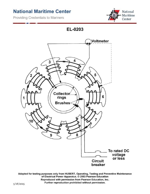
Question: As shown in the illustrated diagnostic setup for locating an open field coil of a ten- pole synchronous motor, if 240 VDC is applied across the brushes, what statement is true if one of the field coils is open-circuited? Illustration EL-0203
A. The voltage across the collector ring and any point before the open will be line voltage and the voltage across the collector ring and any point after the open will be zero voltage.
B. The voltage across the collector ring and any point before or after the open will be line voltage.
C. The voltage across the collector ring and any point before the open will be zero voltage and the voltage across the collector ring and any point after the open will be line voltage.
D. The voltage across the collector ring and any point before or after the open will be zero voltage.
The correct answer is C) The voltage across the collector ring and any point before the open will be zero voltage and the voltage across the collector ring and any point after the open will be line voltage. This is correct because in a synchronous motor with an open-circuited field coil, the voltage across the collector ring and any point before the open will be zero, as the field current cannot flow through the open circuit. However, the voltage across the collector ring and any point after the open will be the full line voltage (240 VDC in this case) since the rest of the field coils are still energized. The other options are incorrect because they do not accurately describe the voltage behavior across the collector ring and points before and after the open field coil.
Question 129
Question: In the illustration what is the component labeled "C"? Illustration EL-0033
A. trip bar
B. connection terminal
C. moving contact
D. fixed contact
The correct answer is D) fixed contact. The fixed contact is the stationary part of an electrical circuit that remains in a fixed position, while the moving contact is the part that moves to make or break the connection. In the illustration EL-0033, the component labeled "C" represents the fixed contact, which is the stationary part of the electrical circuit that the moving contact connects to. The other options are incorrect because: A) a trip bar is a mechanical device that trips a circuit breaker, B) a connection terminal is where wires are connected, and C) the moving contact is the part that moves to make or break the connection, which is a different component from the fixed contact.
Question 131
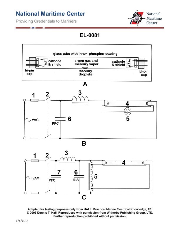
Question: Which of the listed types of lighting fixtures does the diagram shown in figure "A" of the illustration represent? Illustration EL-0081
A. Low pressure mercury fluorescent
B. High pressure mercury fluorescent
C. Low voltage quartz
D. High pressure sodium
The correct answer is A) Low pressure mercury fluorescent. The diagram shown in figure "A" of the illustration EL-0081 represents a low pressure mercury fluorescent lighting fixture. This type of lighting fixture is commonly used in indoor and outdoor applications due to its energy efficiency and long lifespan. The low pressure mercury vapor within the fluorescent tube generates ultraviolet radiation, which in turn excites a phosphor coating on the inside of the tube, producing visible light. The other answer choices are incorrect because high pressure mercury fluorescent fixtures, low voltage quartz lamps, and high pressure sodium lamps have different operating principles and physical characteristics that do not match the diagram shown in the illustration.
Question 132
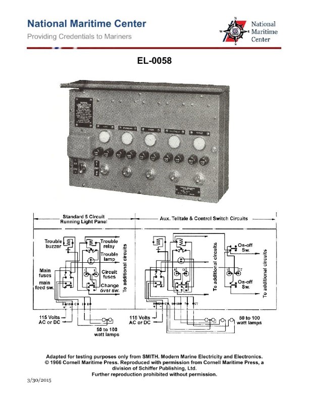
Question: What type of circuit is represented by the diagram shown in the illustration? Illustration EL-0058
A. dual speed, 2-winding motor controller circuit
B. common fluorescent lighting circuit
C. uninterruptible power supply circuit
D. navigation running light circuit
The correct answer is D) navigation running light circuit. The diagram shown in the illustration EL-0058 represents a navigation running light circuit, which is a common electrical system used on vessels to comply with Coast Guard regulations. Navigation running lights are required to be displayed on vessels for visibility and safety purposes, and the circuit diagram demonstrates the typical wiring and components involved in this type of system. The other answer choices are incorrect because they do not accurately describe the type of circuit represented in the illustration. A dual-speed, 2-winding motor controller circuit, a common fluorescent lighting circuit, and an uninterruptible power supply circuit are all different types of electrical systems that do not match the specific requirements and configuration of a navigation running light circuit.
Question 133
Question: As shown in the illustration, what event would give the same indication that would occur when a stern light circuit fuse blows open? Illustration EL-0058
A. stern light "2" burns out
B. trouble buzzer coil open circuits
C. trouble relay normally closed contacts open
D. stern light trouble lamp burns out
The correct answer is A) stern light "2" burns out. When the stern light circuit fuse blows open, the stern light "2" will go out, indicating the same visual cue as when the stern light itself burns out. This is because the blown fuse interrupts the electrical circuit powering the stern light, causing it to extinguish. The other options are incorrect because they do not directly relate to the visual indication of the stern light going out. A trouble buzzer coil or relay opening would not produce the same visual effect, and a trouble lamp burning out is not the same as the stern light itself going dark.
Question 134
Question: What is the purpose of the capacitor within component "5" of the circuit shown in figure "B" of the illustration? Illustration EL-0081
A. counteract the inductive reactance in the circuit
B. discharge the neon within the envelope
C. store power to operate the circuit should "D" open
D. prolong the life of the component's contacts
The correct answer is D) prolong the life of the component's contacts. The capacitor in component "5" of the circuit shown in figure "B" of illustration EL-0081 is used to prolong the life of the component's contacts. When a circuit is opened or closed, the inductive reactance in the circuit can cause arcing across the contacts, which can eventually lead to wear and failure. The capacitor helps to dissipate this inductive energy, reducing the arcing and prolonging the life of the contacts. The other options are incorrect because: A) the capacitor is not used to counteract inductive reactance, B) the capacitor is not connected to a neon envelope, and C) the capacitor is not used to store power to operate the circuit.
Question 135
Question: As shown in the illustration, the change-over switch is what type of device? Illustration EL-0058
A. single-pole, single-throw switch
B. double-pole, single-throw switch
C. single-pole, double-throw switch
D. double-pole, double-throw switch
The correct answer is D) double-pole, double-throw switch. The change-over switch shown in the illustration EL-0058 is a double-pole, double-throw (DPDT) switch. This type of switch has two poles (circuits) and can connect each pole to either of two separate throws (positions). This allows the switch to select between two different circuits or power sources. The other options are incorrect because a single-pole, single-throw switch has only one circuit and one position, a double-pole, single-throw switch has two circuits but only one position, and a single-pole, double-throw switch has one circuit that can connect to either of two positions.
Question 136
Question: Refer to the simplified schematic of the Ward-Leonard drive system shown in the illustration. What statement is true concerning the acceleration of the DC winch motor from base speed to maximum speed at constant horsepower? Illustration EL-0153
A. With a constant DC generator armature RPM at rated speed and the DC generator field current at maximum, the DC winch motor speed increases with increased DC motor field current from minimum to maximum.
B. With a constant DC generator armature RPM at rated speed and the DC generator field current at minimum, the DC winch motor speed increases with decreased DC motor field current from maximum to minimum.
C. With a constant DC generator armature RPM at rated speed and the DC generator field current at minimum, the DC winch motor speed increases with increased DC motor field current from minimum to maximum.
D. With a constant DC generator armature RPM at rated speed and the DC generator field current at maximum, the DC winch motor speed increases with decreased DC motor field current from maximum to minimum.
The correct answer is D) With a constant DC generator armature RPM at rated speed and the DC generator field current at maximum, the DC winch motor speed increases with decreased DC motor field current from maximum to minimum. This is correct because in a Ward-Leonard drive system, the speed of the DC winch motor is controlled by adjusting the DC motor field current. With a constant generator armature speed and maximum generator field current, decreasing the DC motor field current will increase the motor speed, allowing the winch to accelerate from base speed to maximum speed at constant horsepower. The other options are incorrect because they describe the opposite relationship between motor field current and speed, which is not consistent with the operating principles of a Ward-Leonard drive.
Question 137
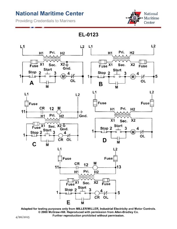
Question: Refer to the simplified schematic of the various types of self-excited DC generators shown in the illustration. What is the configuration of figure "B"? Illustration EL-0123
A. Cumulatively compounded short-shunt
B. Differentially compounded short-shunt
C. Differentially compounded long-shunt
D. Cumulatively compounded long-shunt
The correct answer is D) Cumulatively compounded long-shunt. In a cumulatively compounded long-shunt DC generator, the series field winding is connected in series with the armature, and the shunt field winding is connected in parallel with both the armature and the series field. This configuration results in the series field and shunt field windings adding their respective magnetic fields, which increases the overall excitation of the generator. The "long-shunt" refers to the shunt field winding being connected across the entire generator output. The other options are incorrect because: A) is a cumulatively compounded short-shunt configuration, B) is a differentially compounded short-shunt configuration, and C) is a differentially compounded long-shunt configuration, all of which differ from the configuration shown in figure "B" of the illustration.
Question 138
Question: Refer to the simplified schematic of the Ward-Leonard drive system shown in the illustration. What statement is true concerning the acceleration of the DC winch motor from minimum to base speed at constant torque? Illustration EL-0153
A. With a constant DC generator field current at maximum value, the DC winch motor speed increases with DC generator armature RPM.
B. With a constant DC generator armature RPM at minimum speed, the DC winch motor speed increases with increased DC generator field current from minimum to maximum.
C. With a constant DC generator field current at minimum value, the DC winch motor speed increases with DC generator armature RPM.
D. With a constant DC generator armature RPM at rated speed, the DC winch motor speed increases with increased DC generator field current from minimum to maximum.
The correct answer is D. With a constant DC generator armature RPM at rated speed, the DC winch motor speed increases with increased DC generator field current from minimum to maximum. This is because increasing the DC generator field current increases the magnetic flux in the generator, which in turn increases the voltage generated by the DC generator. This higher generator voltage then allows the DC winch motor to run at a higher speed, while maintaining constant torque. The other options are incorrect because they do not accurately describe the relationship between the DC generator parameters and the resulting DC winch motor speed under constant torque conditions.
Question 140
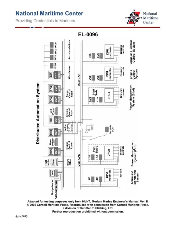
Question: As shown in the illustrated block diagram for a distributed automation system, what statement is true concerning the units labeled "WCU" in the accommodations? Illustration EL-0096
A. These are watch control units extending remote operating system functionality to engineer staterooms on vessels with engine rooms requiring 24-hour manning of watches.
B. These are watch cabin units extending the alarm system to engineer staterooms on vessels with engine rooms requiring 24-hour manning of watches.
C. These are watch cabin units extending the alarm system to engineer staterooms on vessels with periodically unmanned engine rooms.
D. These are watch control units extending remote operating system functionality to engineer staterooms on vessels with periodically unmanned engine rooms.
The correct answer is C. The statement "These are watch cabin units extending the alarm system to engineer staterooms on vessels with periodically unmanned engine rooms" is true. The units labeled "WCU" in the accommodations are watch cabin units that provide a means to monitor the alarm system and status of the engine room in situations where the engine room may be periodically unmanned. The other options are incorrect because: A) and D) refer to "watch control units" extending remote operating system functionality, which is not what the WCU units are for in this case. B) refers to extending the alarm system to engineer staterooms on vessels with 24-hour engine room manning, which does not match the scenario described in the question.
Question 141
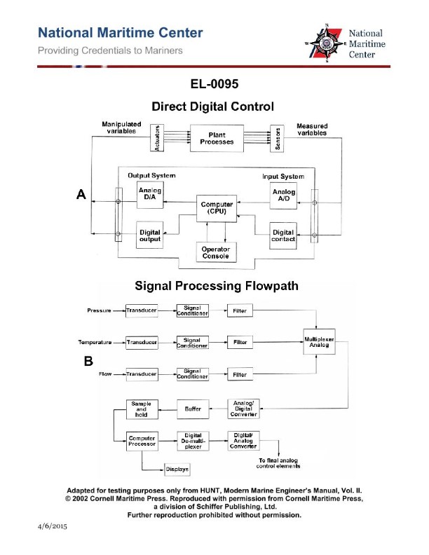
Question: As shown in figure "B" of the illustrated block diagram of the signal processing flow path, the block "TRANSDUCER" represents a sensing and transmitting device designed to sense and measure a physical parameter and convert it into a proportional force or signal of what type? Illustration EL-0095
A. digital electrical signal
B. electromechanical force
C. analog electrical signal
D. pneumatic signal
The correct answer is C) analog electrical signal. The "TRANSDUCER" block in the illustrated signal processing flow path represents a device designed to sense and measure a physical parameter and convert it into a proportional analog electrical signal. Transducers are commonly used to convert physical quantities like pressure, temperature, or flow rate into corresponding electrical signals that can be further processed and analyzed. The other options are incorrect because: A) a digital electrical signal is a discrete, numerical representation of the physical parameter, not a proportional analog signal; B) an electromechanical force is the output of the transducer, not the type of signal it produces; and D) a pneumatic signal is a pressure-based signal, not an electrical one.

Question 142
Question: As shown in the illustrated block diagram for a digitized echo sounding system, what statement is true concerning the function of the transducer? Illustration EL-0185
A. The transducer converts audio frequency (AF) electromagnetic energy to acoustic energy while transmitting and converts the reflected acoustic energy back into AF electromagnetic energy while receiving.
B. The transducer converts radio frequency (RF) electromagnetic energy to acoustic energy while transmitting and converts the reflected acoustic energy back into RF electromagnetic energy while receiving.
C. The transducer converts radio frequency (RF) electromagnetic energy to acoustic energy while receiving and converts the reflected acoustic energy back into RF electromagnetic energy while transmitting.
D. The transducer converts audio frequency (AF) electromagnetic energy to acoustic energy while receiving and converts the reflected acoustic energy back into AF electromagnetic energy while transmitting.
The correct answer is B. The transducer in a digitized echo sounding system converts radio frequency (RF) electromagnetic energy to acoustic energy while transmitting, and then converts the reflected acoustic energy back into RF electromagnetic energy while receiving. This is the fundamental function of a transducer in an echo sounder - to convert between electrical and acoustic energy in order to transmit a signal and receive the echoes. The other options are incorrect because they do not accurately describe the transducer's function. Options A, C, and D incorrectly state that the transducer uses audio frequency (AF) or transmits while receiving, which is not how echo sounders operate.
Question 143
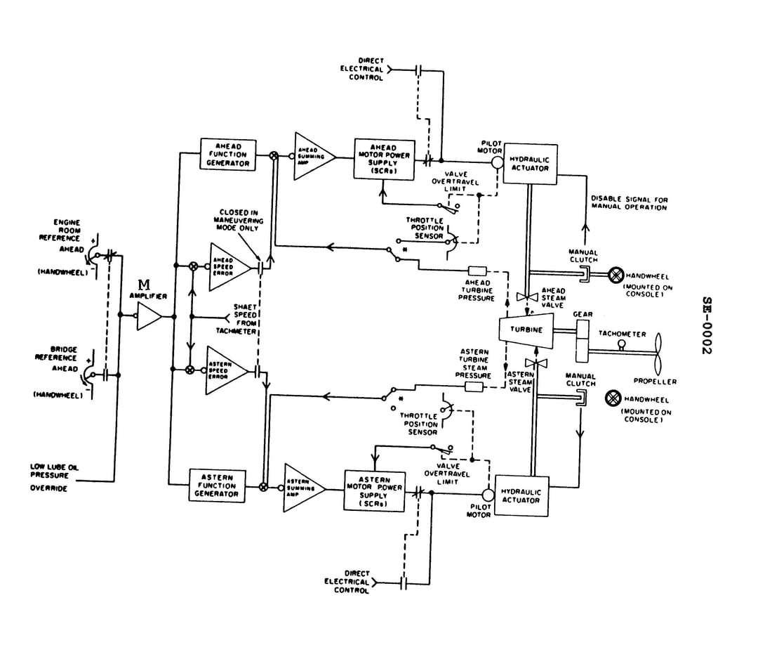
Question: In the illustrated throttle control system, the amplifier 'M" functions to invert the signal received from the engine room or bridge reference potentiometer as appropriate. According to the operating mode selected for in the illustration, moving the engine room reference potentiometer in the direction indicated will have what effect? Illustration SE-0002
A. It will cause a negative signal to be processed by the ahead function generator ultimately causing the astern throttle valve to open wider.
B. It will cause a negative signal to be processed by the ahead function generator ultimately causing the ahead throttle valve to open wider.
C. It will cause a positive signal to be processed by the ahead function generator ultimately causing the ahead throttle valve to open wider.
D. No signal will be processed because the bridge is currently in control of the throttles.
The correct answer is C. According to the information provided, the amplifier "M" functions to invert the signal received from the engine room or bridge reference potentiometer. In the illustrated operating mode, moving the engine room reference potentiometer in the direction indicated will cause a positive signal to be processed by the ahead function generator, ultimately causing the ahead throttle valve to open wider. This is because the amplifier "M" inverts the signal, turning a negative input from the engine room reference potentiometer into a positive signal for the ahead function generator. The other options are incorrect because they do not accurately describe the effect of the inverted signal on the throttle control system.
Question 144
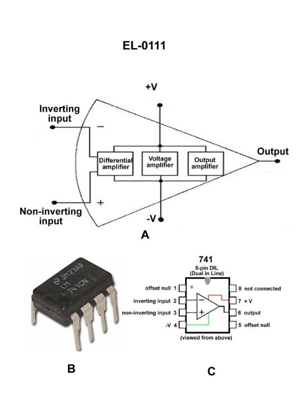
Question: As shown in figures "A", "B", and "C" of the illustration, what is the purpose of the differential amplifier segment of the 741 operational amplifier? Illustration EL-0111
A. detect and amplify the voltage difference between the inputs at pins 1 and 2
B. detect and amplify the voltage difference between the inputs at pins 1 and 5
C. detect and amplify the voltage difference between the inputs at pins 2 and 3
D. detect and amplify the voltage difference between the inputs at pins 3 and 5
The correct answer is C) detect and amplify the voltage difference between the inputs at pins 2 and 3. The purpose of the differential amplifier segment in a 741 operational amplifier is to detect and amplify the voltage difference between the two input pins, which are pins 2 and 3. This differential amplifier configuration allows the op-amp to amplify the difference between the two input signals, which is a key function of operational amplifiers. The other answer choices are incorrect because they do not correctly identify the input pins that the differential amplifier is designed to monitor and amplify the voltage difference between.
Question 145
Question: As shown in the illustrated block diagram for a distributed automation system, what statement is true concerning the area networks? Illustration EL-0096
A. The LAN is a single non-redundant network and the partitioned CAN is a dual redundant network, with both networks being interconnected.
B. The LAN is a dual redundant network and the partitioned CAN is also a dual redundant network, with no interconnectivity between the two networks.
C. The LAN is a dual redundant network and the partitioned CAN is also a dual redundant network, with both networks being interconnected.
D. The LAN is a single non-redundant network and the partitioned CAN is a dual redundant network, with no interconnectivity between the two networks.
The correct answer is C. The LAN is a dual redundant network and the partitioned CAN is also a dual redundant network, with both networks being interconnected. This is the correct answer because the illustrated block diagram shows a distributed automation system with a dual redundant LAN and a dual redundant partitioned CAN, and these two networks are interconnected. This architecture provides redundancy and resilience in the system's communication networks. The other answer choices are incorrect because they do not accurately describe the network architecture shown in the illustration. Option A and D incorrectly state that the LAN is a single non-redundant network, and option B incorrectly states that the two networks are not interconnected.
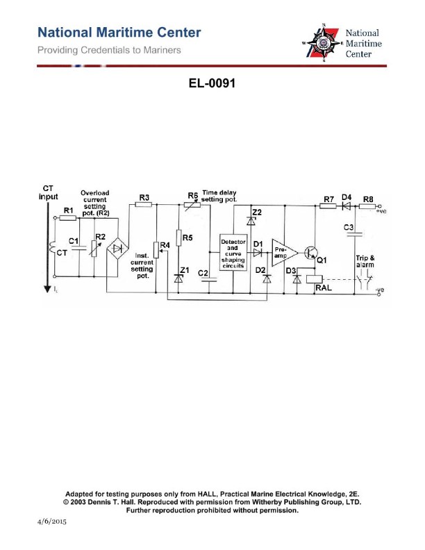
Question 148
Question: What does the circuit shown in the illustration represent? Illustration EL-0091
A. voltage regulator
B. function generator
C. electronic overload relay
D. oscillator
The correct answer is C) electronic overload relay. The circuit shown in the illustration EL-0091 represents an electronic overload relay, which is a safety device used to protect electrical equipment from excessive current or overload conditions. The relay is designed to detect when the current flowing through a circuit exceeds a predetermined threshold and then disconnect the power supply to prevent damage to the equipment. The other answer choices are incorrect because: A) A voltage regulator is used to maintain a constant output voltage, not to detect overload conditions. B) A function generator is used to generate various waveforms, not to protect against overloads. D) An oscillator is a circuit that generates a periodic signal, not an overload protection device.
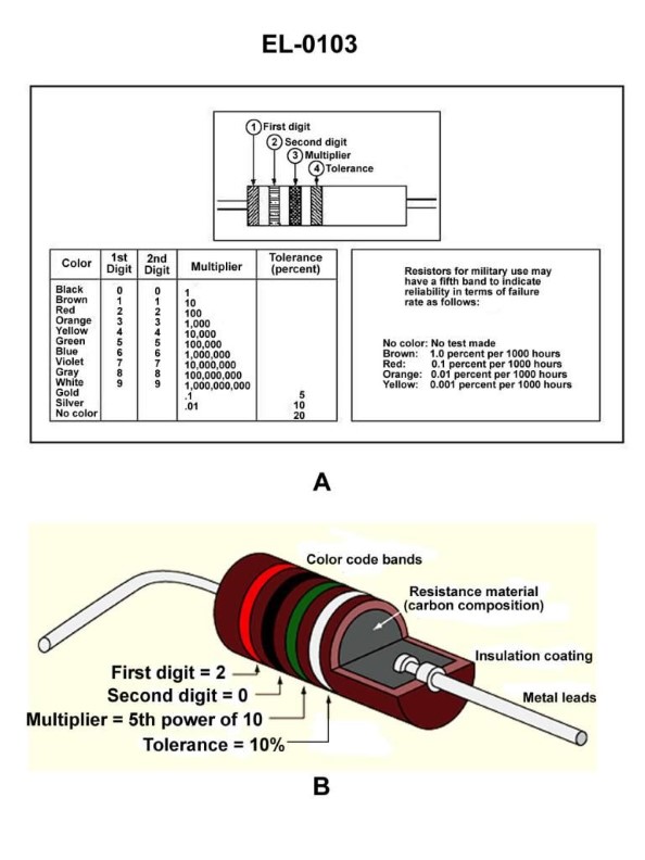
Question 149
Question: What would be the resistance tolerance of a carbon resistor which is color coded as red, violet, brown, and silver in bands 1 thru 4 respectfully as shown in figure "A" of the illustration? Illustration EL-0103
A. 1%
B. 5%
C. 10%
D. 20%
The correct answer is C) 10%. The color coding of the resistor bands indicates the resistance value and tolerance: - Red, violet, brown: The first three bands indicate the resistance value, which is 27,000 ohms (2,700 x 10^2). - Silver: The fourth band indicates the tolerance, which is 10%. The other answer choices are incorrect because: A) 1% is too tight of a tolerance for a standard carbon resistor. B) 5% is also a common tolerance, but not the one indicated by the silver band. D) 20% is too wide of a tolerance for this type of resistor.
Question 153
Question: A carbon resistor has the following color bands; band 1 is yellow, band 2 is violet, band 3 is yellow, and band 4 is silver. What is the value of the resistor in ohms, as well as the tolerance? Illustration EL-0103
A. 74 ohms + or - 5%
B. 4,700 ohms + or - 10%
C. 74,000 ohms + or - 5%
D. 470,000 ohms + or - 10%
The correct answer is D) 470,000 ohms + or - 10%. To determine the value of the resistor, we need to interpret the color bands according to the standard resistor color code. The first two bands represent the first two digits of the resistance value, while the third band represents the multiplier. The fourth band indicates the tolerance. In this case, the color bands are yellow (4), violet (7), and yellow (4), which translates to a resistance value of 470,000 ohms. The silver fourth band indicates a tolerance of +/- 10%. The other options are incorrect because they do not correctly interpret the color bands or the tolerance value.
Question 156
Question: A carbon resistor has a resistance of 50 ohms, and a tolerance of 5 percent. What would be the respective colors indicated for bands 1, 2, 3 and 4 for this resistor as shown in figure "A" of the illustration? Illustration EL-0103
A. green, black, black, and silver.
B. green, black, black, and gold.
C. gray, black, brown, and silver.
D. gray, black, brown, and gold.
The correct answer is B) green, black, black, and gold. This is correct because the color bands on a resistor follow a standard color coding system that indicates the resistor's resistance value and tolerance. For a 50-ohm resistor with a 5% tolerance: - The first band is green, which represents the first digit of the resistance value (5). - The second band is black, which represents the second digit of the resistance value (0). - The third band is black, which represents the multiplier (x1 or 10^0). - The fourth band is gold, which represents the tolerance of 5%. The other options are incorrect because they do not match the proper color coding for a 50-ohm, 5% tolerance resistor.
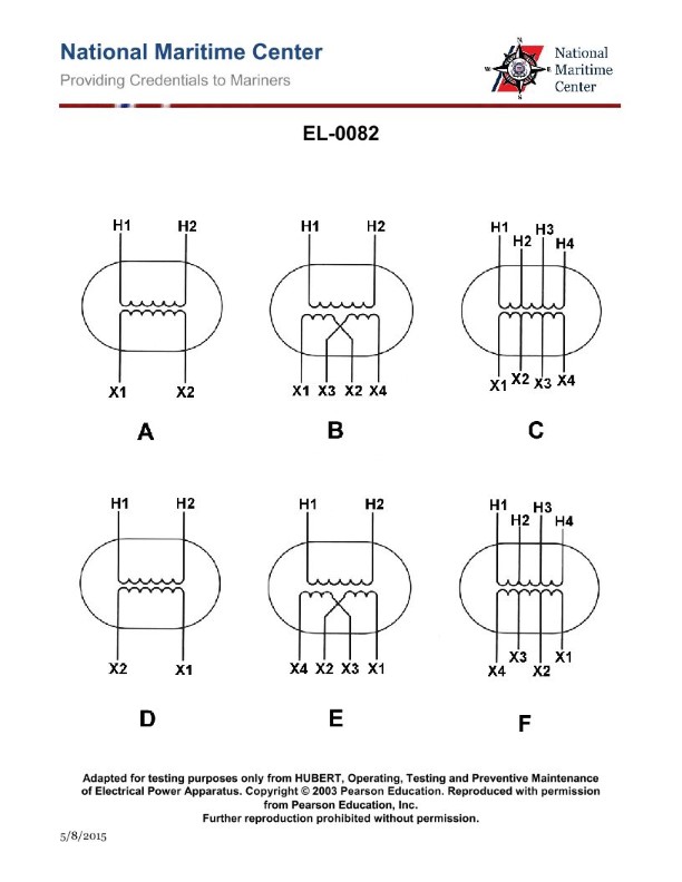
Question 158
Question: The turn’s ratio of the step-down transformer with dual voltage secondary shown in figure "B" of the illustration is two to one (total). If 220 volts were applied to terminals 'H1' and 'H2', what would be measured across 'X3' and 'X4'? Illustration EL-0082
A. 55 volts
B. 110 volts
C. 440 volts
D. 880 volts
The correct answer is A) 55 volts. In a step-down transformer with a 2:1 turns ratio, the secondary voltage will be half the primary voltage. Since the primary voltage is 220 volts, the secondary voltage across terminals X3 and X4 will be 220 volts / 2 = 110 volts. The other options are incorrect because: B) 110 volts is the voltage across the entire secondary winding, not just terminals X3 and X4. C) 440 volts and D) 880 volts are incorrect as they do not match the 2:1 turns ratio of the transformer.
Question 161
Question: Refer to the simplified schematic of the Ward-Leonard drive system shown in the illustration. The DC winch exhibits normal speed control from minimum to base speed, but the speed cannot be elevated above base speed. What condition would account for this? Illustration EL-0153
A. A short-circuited DC motor field control rheostat.
B. An open-circuited DC generator field winding.
C. An open-circuited DC winch motor field winding.
D. A failure of the DC static power supply to produce a voltage.
The correct answer is A) A short-circuited DC motor field control rheostat. In a Ward-Leonard drive system, the speed of the DC winch motor is controlled by varying the strength of the motor's field winding. If the DC motor field control rheostat is short-circuited, it would prevent the field strength from being adjusted above the base speed, resulting in the observed speed behavior where the speed cannot be elevated above the base speed. The other options are incorrect because: B) An open-circuited DC generator field winding would prevent any speed control, not just the inability to exceed base speed. C) An open-circuited DC winch motor field winding would result in the motor not operating at all, not just a limited speed range. D) A failure of the DC static power supply would prevent the system from functioning altogether, not just limit the speed range.
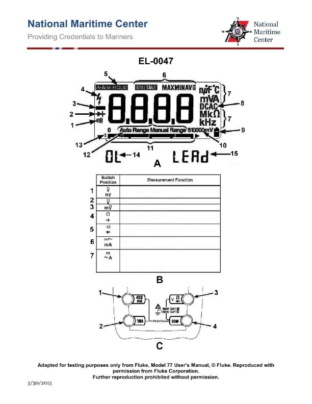
Question 165
Question: As shown in figure "A" of the illustrated digital multimeter screen, what would be the significance of the symbol indicated by "1" being illuminated? Illustration EL-0047
A. the meter is subjected to a potentially unsafe voltage
B. the meter is in range of a wireless signal
C. the selector switch is selected for continuity/diode test and the secondary function push button is toggled for continuity
D. The meter test leads are placed in the wrong terminal jacks for the test being performed
The correct answer is C) the selector switch is selected for continuity/diode test and the secondary function push button is toggled for continuity. The symbol indicated by "1" on the digital multimeter screen is typically used to indicate that the meter is in the continuity test mode. This means the meter is set to check for a complete circuit between the test leads, which is useful for testing wiring, components, and connections. The other answer choices are incorrect because: A) The continuity test mode does not indicate an unsafe voltage. B) The continuity test mode is not related to the presence of a wireless signal. D) The continuity test mode is the intended function when the symbol "1" is displayed, not an indication of the test leads being in the wrong terminal jacks.

Question 169
Question: As shown in figure "D" of the illustrated digital power meter, what type of single- phase load is under test for power measurement? Illustration EL-0256
A. a purely inductive load
B. a purely resistive load
C. a resistive-capacitive load
D. an inductive-resistive load
The correct answer is D) an inductive-resistive load. The explanation is as follows: 1. The illustration EL-0256 shows a digital power meter displaying various electrical parameters, and the question specifically refers to the information shown in "Figure D" of this illustration. This figure depicts a single-phase load that exhibits both inductive and resistive characteristics, which is characteristic of an inductive-resistive load. 2. For a single-phase power measurement, an inductive-resistive load is the most common type of load encountered, as it represents a combination of resistive and inductive elements, such as a motor or transformer. 3. The other options are incorrect because a purely inductive load (A) would not exhibit any resistive component, and a purely resistive load (B) or a resistive-capacitive load (C) would not have an inductive component. 4. Therefore, the correct answer is D) an inductive-resistive load, based on the information provided in the illustration and the typical characteristics of single-phase power measurements.
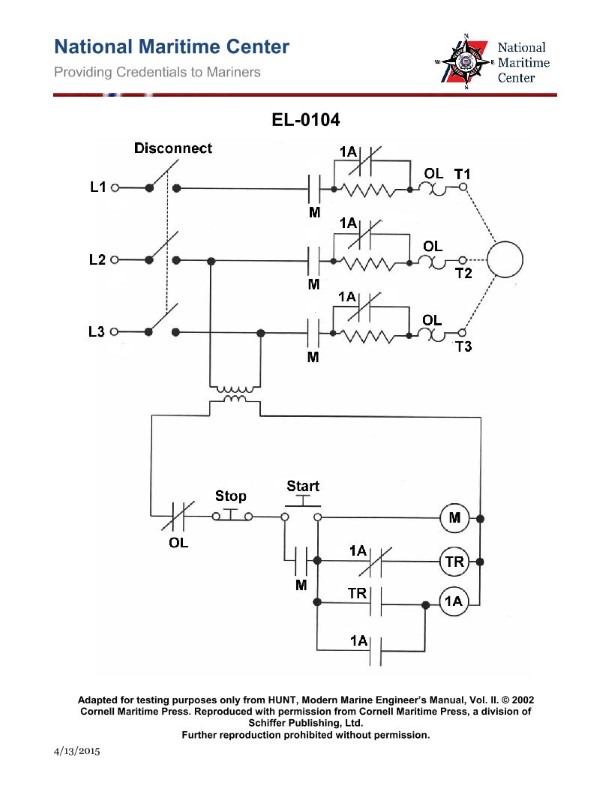
Question 177
Question: As shown in the illustration, what is the purpose of the Time Delay (TR) coil in the circuit? Illustration EL-0104
A. Ensures the motor cannot be started until the overload relays are reset.
B. Allows the motor to come up to speed at reduced voltage before bypassing the starting resistors.
C. Ensures the motor cannot be started until the accelerating coil is energized.
D. Allows the motor to come up to speed before placing the starting resistors in the circuit.
The correct answer is B) Allows the motor to come up to speed at reduced voltage before bypassing the starting resistors. The time delay (TR) coil in the circuit serves to delay the bypassing of the starting resistors until the motor has had a chance to come up to speed at a reduced voltage. This ensures a smooth, controlled acceleration of the motor rather than abruptly applying full voltage which could cause issues. The other answer choices are incorrect because they do not accurately describe the purpose of the TR coil in this type of motor control circuit.
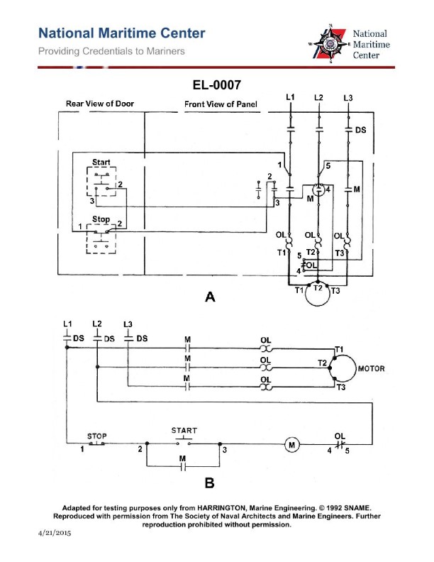
Question 178
Question: In the illustrated motor controller, the motor fails to start. A voltmeter reading between 1 and 5 reads line voltage, while the voltmeter reading between 2 and 5 reads 0 VAC. What is most likely the problem? Illustration EL-0007
A. an open stop switch contact (when not pushed in)
B. an open main contactor "M" coil
C. an overload "OL" relay contact
D. an open start switch contact (when pushed in)
The correct answer is A) an open stop switch contact (when not pushed in). The reasoning is that with line voltage present between terminals 1 and 5, but 0 VAC between terminals 2 and 5, it indicates that the circuit between the stop switch and the main contactor "M" coil is open. This means the stop switch, when not pushed in (i.e., in the open position), is preventing the contactor coil from being energized, which would prevent the motor from starting. The other options are incorrect because an open main contactor coil (B) would result in 0 VAC between all terminals, and an overload relay contact (C) or an open start switch (D) would not explain the specific voltage readings observed.
Question 181
Question: If the motor of the illustrated circuit fails to start and gives a loud hum when the start button is pushed, what is most likely the problem? Illustration EL-0007
A. an open main contactor "M" coil
B. an open overload "OL" relay contact
C. an open overload "OL" heater
D. the disconnect switch "DS" is open
The correct answer is C) an open overload "OL" heater. When the motor fails to start and gives a loud hum, it indicates that the motor is not receiving enough current to start. This is most likely due to an issue with the overload "OL" heater, which is responsible for protecting the motor from overcurrent conditions. If the overload heater is open, it will prevent the necessary current from reaching the motor, causing the observed symptoms. The other answer choices are incorrect because an open main contactor "M" coil (A) would prevent the motor from starting entirely, an open overload "OL" relay contact (B) would also prevent the motor from starting, and an open disconnect switch "DS" (D) would disconnect power to the entire circuit, not just the motor.
Question 182
Question: The motor starts when the start button in the illustration is pushed, but stops when the button is released. What is most likely the trouble? Illustration EL-0007
A. an open in the stop button contact
B. an open "M" contactor coil
C. a corroded contact on the disconnect switch (DS) at 'L3'
D. an open auxiliary "M" contact
The correct answer is D) an open auxiliary "M" contact. When the start button is pushed, it energizes the "M" contactor coil, which then closes the main motor contacts to start the motor. However, when the start button is released, the auxiliary "M" contact is responsible for keeping the "M" contactor coil energized, allowing the motor to continue running. If this auxiliary "M" contact is open, the "M" contactor coil will de-energize as soon as the start button is released, causing the motor to stop. The other options are incorrect because an open in the stop button contact (A) would not allow the motor to start at all, an open "M" contactor coil (B) would prevent the motor from starting, and a corroded contact on the disconnect switch (C) would not specifically cause the motor to stop when the start button is released.
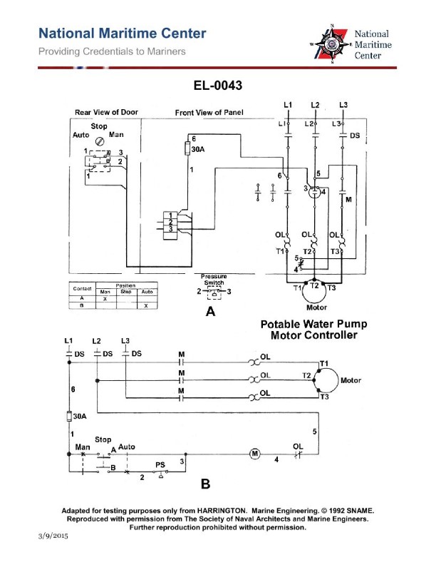
Question 183
Question: As shown in figure "A" and "B" of the illustration, the potable water pump is short cycling by the action of the pressure switch as a result of an unusually high level in the potable water hydro pneumatic header tank. What is most likely the cause? Illustration EL-0043
A. The potable water hydro pneumatic header tank has too much compressed air and some must be bled off.
B. The pressure switch differential setting is set excessively high and the differential must be decreased.
C. The potable water hydro pneumatic header tank is in need of recharging with compressed air due to absorption of air into the water over time.
D. The pressure switch range adjustment is set too low and must be set higher.
The correct answer is C. The potable water hydro pneumatic header tank is in need of recharging with compressed air due to absorption of air into the water over time. As water absorbs air over time, the air cushion in the tank becomes depleted, causing the pressure switch to cycle on and off rapidly (short cycling) in response to the unusually high water level. The other options are incorrect because: A) Bleeding off air from the tank would not address the root cause of the air absorption issue. B) Adjusting the pressure switch differential would not fix the underlying problem of the air cushion depletion. D) Raising the pressure switch range would not resolve the short cycling issue caused by the insufficient air cushion.
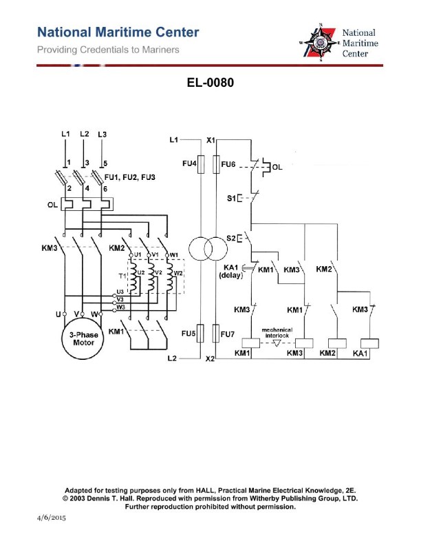
Question 184
Question: As shown in the illustration, what mechanism will disconnect the motor from the line in case of a sustained motor overload? Illustration EL-0080
A. transformer secondary fuses FU6 and FU7
B. disconnect switch fuses FU1, FU2, and FU3
C. transformer primary fuses FU4 and FU5
D. overload relay heaters and overload relay NC contacts (OL)
The correct answer is D) overload relay heaters and overload relay NC contacts (OL). The overload relay is designed to detect a sustained motor overload condition and disconnect the motor from the power source to prevent damage. The overload relay heaters monitor the motor current, and if a sustained overload is detected, the normally closed (NC) overload relay contacts will open, interrupting the motor control circuit and disconnecting the motor. This is the primary mechanism to protect the motor from a sustained overload, making this the correct answer. The other options, such as transformer fuses or disconnect switch fuses, are not the primary mechanism for disconnecting the motor in an overload situation. They may provide overcurrent protection, but the overload relay is the key component designed for this specific purpose.
Question 185
Question: As shown in figure "A" of the illustration, if in troubleshooting the control circuit using on-line techniques with a voltmeter with the start button depressed and the following readings are taken, what is the problem? "X1" to "X2" reads 115 VAC; "1" to "X2" reads 0 VAC; "2" to "X2" reads 0 VAC; and "3" to "X2" reads 0 VAC. Illustration EL-0123
A. the secondary winding of the control transformer is open-circuited
B. the fuse is blown
C. the stop button is open-circuited
D. the start button is open-circuited
The correct answer is B) the fuse is blown. The reasoning is as follows: With the start button depressed, we would expect to see 115 VAC on the control circuit if it were operating properly. However, the readings show 115 VAC at the input ("X1" to "X2"), but 0 VAC at all the other points ("1" to "X2", "2" to "X2", "3" to "X2"). This indicates that the circuit is not being energized, likely due to a blown fuse. The other options are incorrect because an open-circuited secondary winding (A) or open-circuited stop button (C) would not result in the same voltage readings, and the start button being open-circuited (D) would prevent the circuit from being energized at all.
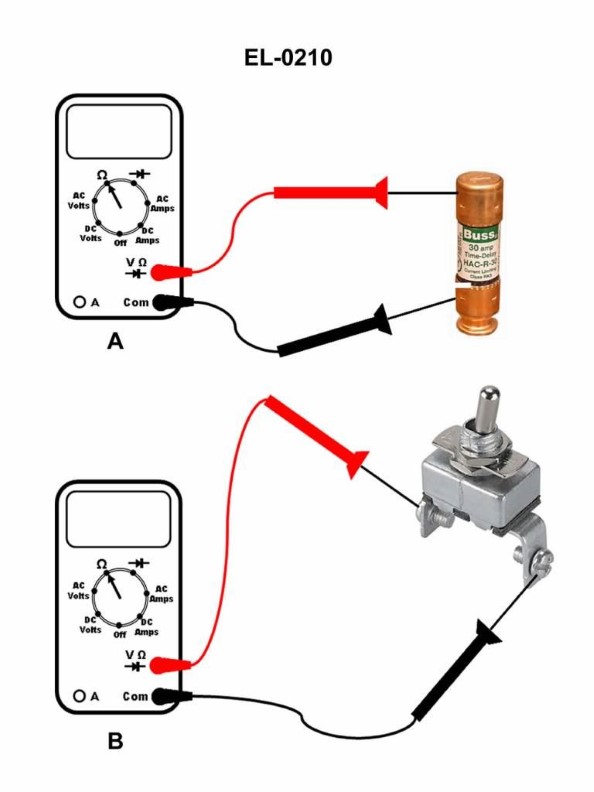
Question 196
Question: If a digital multimeter is set up as shown in figure "A" of the illustration, what would be displayed on the screen if the fuse being tested is blown? Illustration EL-0210
A. OL volts
B. 0.001 ohms
C. 470 ohms
D. OL ohms
The correct answer is D) OL ohms. When a digital multimeter is set up to measure resistance (ohms) and the fuse being tested is blown, the multimeter will display "OL" (Overload) on the screen. This is because a blown fuse has an infinite resistance, which the multimeter cannot measure accurately. The other options are incorrect because they do not reflect the behavior of a digital multimeter when testing a blown fuse.
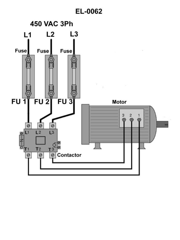
Question 199
Question: In order to definitively determine whether or not fuse "1", shown in the illustration is blown using an on-line testing technique, across what points would you connect the voltmeter leads? Illustration EL-0062
A. from the top of fuse "1" and the top of either fuse "2" or fuse "3"
B. from the bottom of fuse "1" and the bottom of either fuse "2" or fuse "3"
C. from the top of fuse "1" and the bottom of either fuse "2" or fuse "3"
D. from the bottom of fuse "1" and the top of either fuse "2" or fuse "3"
The correct answer is D) from the bottom of fuse "1" and the top of either fuse "2" or fuse "3". The reasoning behind this is that to definitively determine if a fuse is blown, you need to measure the voltage drop across that fuse. By connecting the voltmeter leads from the bottom of fuse "1" to the top of either fuse "2" or "3", you can directly measure the voltage across fuse "1" and determine if it is blown based on the voltage reading. The other options are incorrect because they do not allow you to directly measure the voltage across the specific fuse in question (fuse "1"). Measuring between the tops or bottoms of different fuses would not provide the necessary information to determine the status of fuse "1".
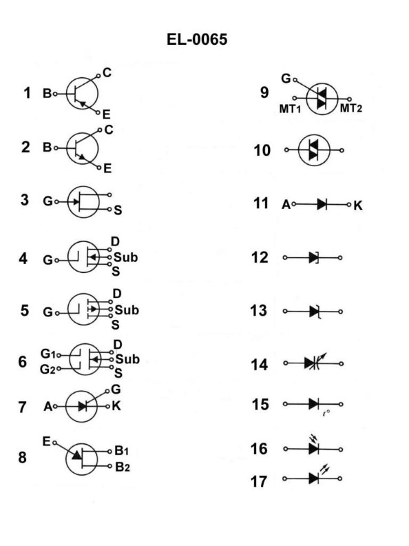
Question 203
Question: As shown in the illustration, which electrical symbol represents a PNP type bipolar junction transistor? Illustration EL-0065
A. 1
B. 2
C. 3
D. 4
The correct answer is A) 1, which represents a PNP type bipolar junction transistor. The illustration EL-0065 shows the standard electrical symbols for various electronic components, and the symbol labeled 1 is the correct representation of a PNP bipolar junction transistor. This is in accordance with the standard electrical schematic conventions used in the US Coast Guard Captain's License Examinations. The other options, B) 2, C) 3, and D) 4, represent different electronic components such as an NPN transistor, a diode, and a resistor, respectively, and are not the correct symbol for a PNP bipolar junction transistor.
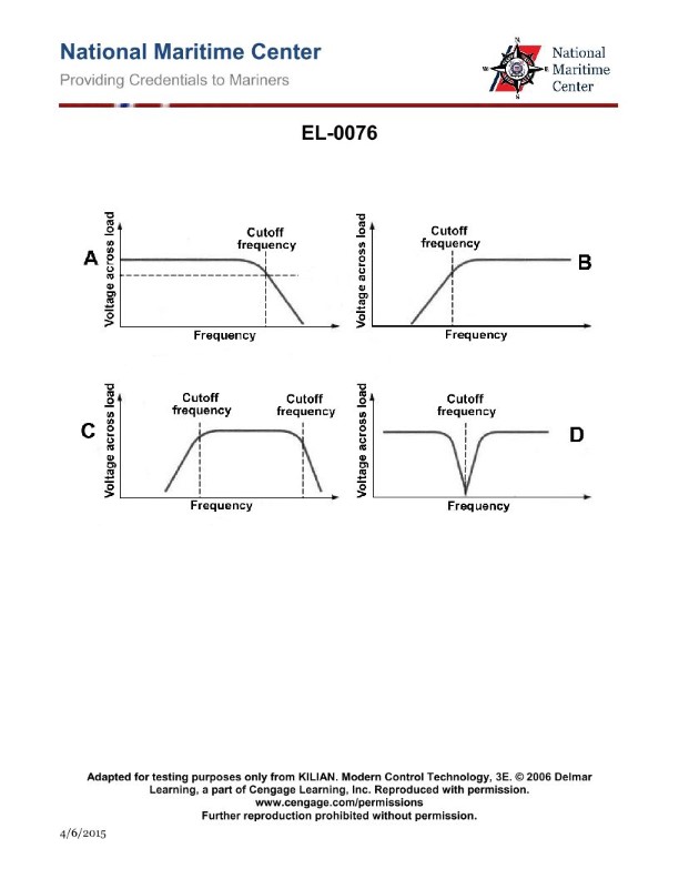
Question 205
Question: As shown in figure "A" of the illustration, what is true concerning the illustrated frequency response curve? Illustration EL-0076
A. Low frequencies below the cutoff-frequency are attenuated and high frequencies above the cutoff-frequency are attenuated.
B. Low frequencies below the cutoff-frequency are passed and high frequencies above the cutoff-frequency are attenuated.
C. Low frequencies below the cutoff-frequency are passed and high frequencies above the cutoff-frequency are passed.
D. Low frequencies below the cutoff-frequency are attenuated and high frequencies above the cutoff-frequency are passed.
The correct answer is D) Low frequencies below the cutoff-frequency are attenuated and high frequencies above the cutoff-frequency are passed. This is correct because the illustrated frequency response curve depicts a high-pass filter, where low frequencies below the cutoff-frequency are attenuated, while high frequencies above the cutoff-frequency are passed through. This type of filter is commonly used to remove unwanted low-frequency signals, such as hum or rumble, while preserving the desired high-frequency content. The other options are incorrect because they do not accurately describe the behavior of a high-pass filter. Option A describes a band-pass filter, option B describes a low-pass filter, and option C describes a flat, non-filtering response, which is not the case for the illustrated frequency response curve.
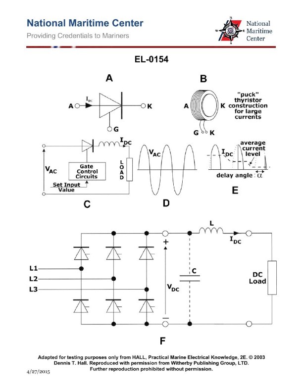
Question 206
Question: As shown in figure "A" of the illustration, under what conditions will the thyristor conduct? Illustration EL-0154
A. when the anode is more positive than the cathode and when the gate is briefly pulsed with a voltage more positive than the cathode
B. when the anode is more negative than the cathode and when the gate is briefly pulsed with a voltage more positive than the cathode
C. when the anode is more positive than the cathode and when the gate is briefly pulsed with a voltage more negative than the cathode
D. when the anode is more negative than the cathode and when the gate is briefly pulsed with a voltage more negative than the cathode
The correct answer is A) when the anode is more positive than the cathode and when the gate is briefly pulsed with a voltage more positive than the cathode. For a thyristor to conduct, two conditions must be met: 1) the anode must be more positive than the cathode, and 2) the gate must be briefly pulsed with a voltage more positive than the cathode. This triggers the thyristor to turn on and allow current to flow from the anode to the cathode. The other answer choices are incorrect because they describe conditions that would either prevent the thyristor from conducting (B and D) or require the gate to be pulsed with a negative voltage, which is not how a thyristor operates (C).
Question 207
Question: What does the electronic symbol of figure "9" represent? Illustration EL-0065
A. triac thyristor
B. zener diode
C. diac trigger diode
D. diode rectifier
A) triac thyristor is the correct answer. The electronic symbol of figure "9" represents a triac thyristor, which is a three-terminal semiconductor device used for controlling alternating current (AC) circuits. Triacs are commonly used in applications such as light dimmers, motor controls, and other power electronics where bidirectional control of AC power is required. The other options are incorrect because: B) a zener diode is a two-terminal semiconductor device used for voltage regulation, C) a diac trigger diode is a two-terminal semiconductor device used for triggering triacs or thyristors, and D) a diode rectifier is a two-terminal semiconductor device used for converting AC to DC.
Question 210
Question: Referring to the illustration of a DC diesel-electric drive system, what type of DC propulsion motors are used? Illustration EL-0141
A. shunt wound where the field is separately excited from a controlled rectifier
B. shunt wound where the field is separately excited from a non-controlled rectifier
C. series wound where the field is wired in series with the armature
D. shunt wound where the field is wired in parallel with the armature
The correct answer is B) shunt wound where the field is separately excited from a non-controlled rectifier. In a DC diesel-electric drive system, shunt wound motors are commonly used where the field winding is excited separately from the main armature winding. This allows for independent control of the field current, which is typically provided by a non-controlled rectifier rather than a controlled rectifier. The other options are incorrect because: A) a controlled rectifier would be used for a separately excited field, C) a series wound motor has the field winding in series with the armature, and D) a shunt wound motor has the field winding in parallel with the armature.
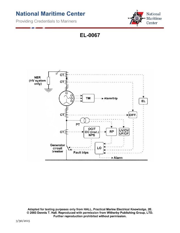
Question 211
Question: As shown in the illustrated alternator protection scheme diagram, what device provides the input to the over current inverse time relay "OCIT", the over current instantaneous trip "OC (inst.)", and the negative phase sequence relay "NPS"? Illustration EL-0067
A. potential transformer
B. current transformer
C. thermal monitor sensors
D. infrared sensors
The correct answer is B) current transformer. The current transformer (CT) provides the input signal to the over current inverse time relay (OCIT), the over current instantaneous trip (OC (inst.)), and the negative phase sequence relay (NPS) in the illustrated alternator protection scheme diagram EL-0067. The CT is responsible for stepping down the high current from the alternator to a lower, safer level that can be used by the protective relays. The other options are incorrect because: A) a potential transformer is used to step down voltage, not current; C) thermal monitors and D) infrared sensors are not the primary source of input to the protective relays shown in the diagram.
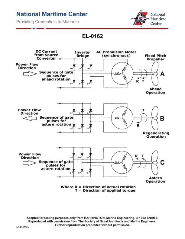
Question 217
Question: As shown in figure "B" of the illustration, what statement is true concerning "regenerating" operation? Illustration EL-0162
A. by applying torque in the same direction of rotation direction, the motor briefly regenerates power back into the mains, which rapidly slows down the motor
B. by applying torque in the same direction of rotation direction, the motor briefly regenerates power back into the mains, which rapidly speeds up the motor
C. by applying torque in the opposite direction of rotation direction, the motor briefly regenerates power back into the mains, which rapidly speeds up the motor
D. by applying torque in the opposite direction of rotation direction, the motor briefly regenerates power back into the mains, which rapidly slows down the motor
The correct answer is D) by applying torque in the opposite direction of rotation direction, the motor briefly regenerates power back into the mains, which rapidly slows down the motor. When a motor is driven in the opposite direction of its current rotation, it acts as a generator, briefly regenerating power back into the electrical mains. This regenerative braking effect rapidly slows down the motor, as the generated power is not used to drive the motor but instead is fed back into the power source. The other options are incorrect because applying torque in the same direction of rotation would accelerate the motor, not slow it down, and regenerating power into the mains would not rapidly speed up the motor, but rather slow it down.
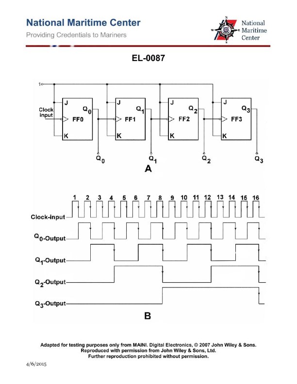
Question 222
Question: If the clock frequency input to the circuit shown in the illustration were 2 kHz, what would be indicated at the output of 'FF-3' at the Q3 output? Illustration EL-0087
A. 125 Hz
B. 250 Hz
C. 500 Hz
D. 1000 Hz
The correct answer is A) 125 Hz. In the circuit shown in the illustration EL-0087, the clock frequency input is 2 kHz. The circuit uses a series of flip-flops (FF-1, FF-2, FF-3) to divide the input frequency down. Each flip-flop divides the frequency by 2, so the output at the Q3 terminal of FF-3 will be 1/8th of the input frequency, which is 2 kHz / 8 = 250 Hz. The other options are incorrect because: B) 250 Hz is the output at the Q2 terminal of FF-2, not the Q3 terminal of FF-3; C) 500 Hz is the output at the Q1 terminal of FF-2, not the Q3 terminal of FF-3; and D) 1000 Hz is the output at the Q0 terminal of FF-1, not the Q3 terminal of FF-3.
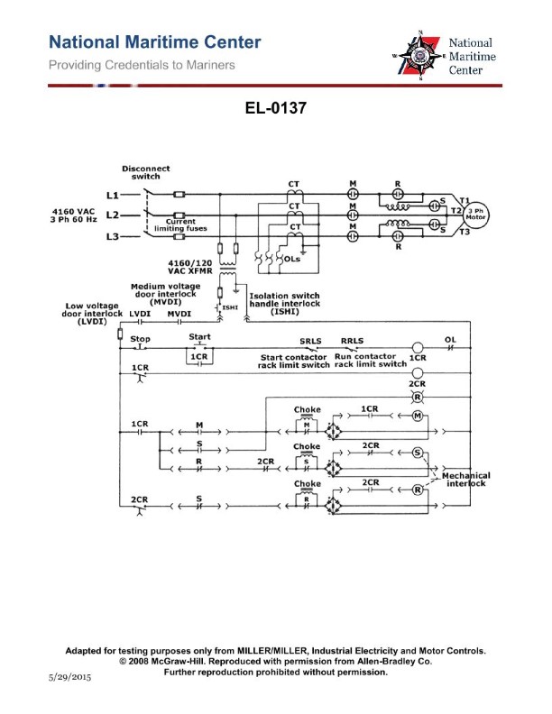
Question 231
Question: As shown in the illustration, what type of motor and motor starter are featured? Illustration EL-0137
A. non-reversing squirrel cage induction motor with reduced voltage primary reactor starting
B. reversing squirrel cage induction motor with reduced voltage autotransformer starting
C. reversing squirrel cage induction motor with across-the-line starting
D. non-reversing squirrel cage induction motor with reduced voltage autotransformer starting
The correct answer is D) non-reversing squirrel cage induction motor with reduced voltage autotransformer starting. This is the correct answer because the illustration EL-0137 depicts a non-reversing squirrel cage induction motor, which is a commonly used motor type in marine applications. The starting method shown is a reduced voltage autotransformer, which is a standard technique to smoothly start and accelerate large induction motors to full speed. The other options are incorrect because option A describes a primary reactor starting method, option B describes a reversing motor, and option C describes an across-the-line (full voltage) starting method, which is less common for large motors.
Question 232
Question: Referring to figure "B" of the illustrated control circuit schematic diagram, which of the following statements is true when the motor is running in the forward direction? Illustration EL-0011
A. The normally open (NO) "F" contacts are closed.
B. The normally closed (NC) "F" contacts are closed.
C. The normally open (NO) "R" contacts are closed.
D. The normally closed (NC) "R" contacts are open.
The correct answer is A) The normally open (NO) "F" contacts are closed. When the motor is running in the forward direction, the normally open "F" contacts would be closed to complete the circuit and allow current to flow to the motor. This is because the "F" contacts are associated with the forward rotation of the motor. The other answer choices are incorrect because: B) The normally closed "F" contacts would be open, not closed, when the motor is running forward. C) The normally open "R" contacts would not be closed, as they are associated with the reverse rotation of the motor. D) The normally closed "R" contacts would be open, not closed, when the motor is running forward.
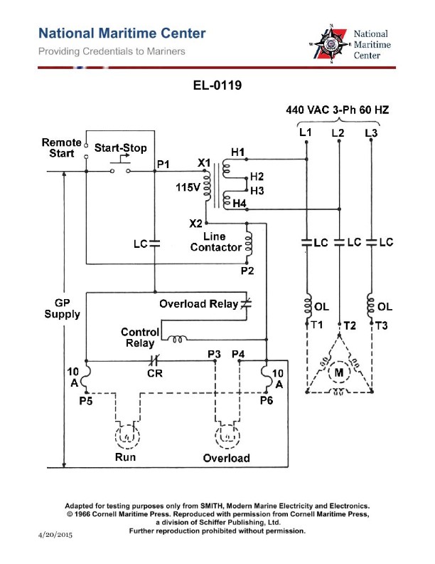
Question 233
Question: As shown in the illustrated steering hydraulic pump motor controller, what statement is true? Illustration EL-0119
A. The pump motor is protected by low voltage release and protected from motor overload by visual warning
B. The pump motor is protected by low voltage release and protected from motor overload by overload trip
C. The pump motor is protected by low voltage protection and protected from motor overload by visual warning
D. The pump motor is protected by low voltage protection and protected from motor overload by overload trip
The correct answer is A) The pump motor is protected by low voltage release and protected from motor overload by visual warning. This is correct because the illustrated steering hydraulic pump motor controller shows that the pump motor is protected by a low voltage release mechanism, which would disconnect the motor if the voltage drops below a safe level. Additionally, the controller indicates that the motor is protected from overload by a visual warning, likely an indicator light or gauge, rather than an overload trip that would automatically disconnect the motor. The other options are incorrect because they do not accurately reflect the protection features shown in the illustration. Options B and D incorrectly state that the motor is protected by an overload trip, and options C and D incorrectly state that the motor is protected by low voltage protection, rather than low voltage release.
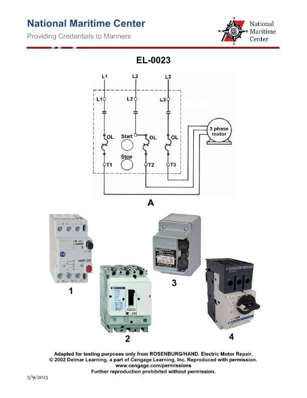
Question 236
Question: Which of the following statements is true concerning the manual motor starter diagram shown in figure "A" of the illustration? EL-0023
A. The motor has three-leg protection by magnetic overloads.
B. The motor has three-leg protection by thermal overloads.
C. The motor has two-leg protection by magnetic overloads.
D. The motor has two-leg protection by thermal overloads.
The correct answer is B) The motor has three-leg protection by thermal overloads. This is the correct answer because in a manual motor starter diagram, the three-leg protection by thermal overloads is the standard configuration to protect the motor from overload conditions. Thermal overloads measure the current flowing through the motor and will trip the starter if the current exceeds a certain threshold, preventing damage to the motor. The other options are incorrect because: A) refers to magnetic overloads, which are less common in manual motor starters; C) and D) mention two-leg protection, which is not the standard configuration for a three-phase motor.
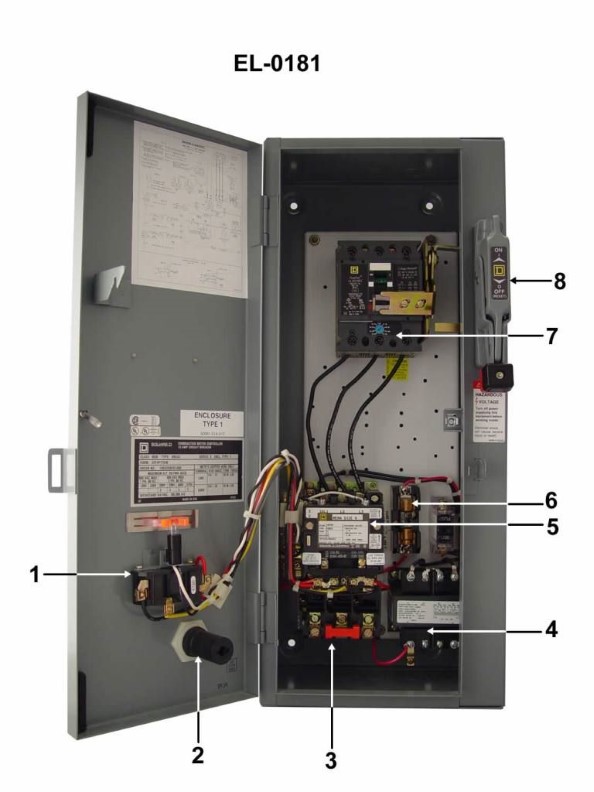
Question 237
Question: What is the proper name for the entire device, including all subassemblies, shown in the illustration? Illustration EL-0181
A. Safety disconnect switch
B. Combination starter
C. Magnetic contactor
D. Magnetic starter
The correct answer is B) Combination starter. A combination starter is the proper name for the entire device shown in the illustration EL-0181. It includes all the necessary subassemblies, such as a magnetic contactor, overload relay, and a disconnecting means, to provide complete motor control and protection. The other options are incorrect because: A) A safety disconnect switch is a separate component that isolates the power supply, not the complete motor control assembly. C) A magnetic contactor is a single component within the combination starter, not the entire device. D) A magnetic starter is an older term that refers to the same type of device as a combination starter.
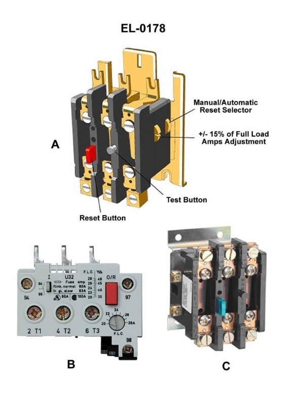
Question 238
Question: As shown in figure "A" of the illustration, what is the purpose of the "test button"? EL-0178
A. The test button is used to reset the now open normally closed relay contacts after an overload trip.
B. The test button is used to reset the now closed normally open relay contacts after an overload trip.
C. The test button is used to mimic an overload to test the trip function of the overload relay.
D. The test button is used to test the actual current trip value of the overload relay.
The correct answer is C) The test button is used to mimic an overload to test the trip function of the overload relay. The purpose of the test button is to simulate an overload condition and verify that the overload relay will trip as intended. This allows the operator to test the functionality of the overload protection system without actually subjecting the equipment to an overload. The other answer choices do not accurately describe the purpose of the test button in this context.
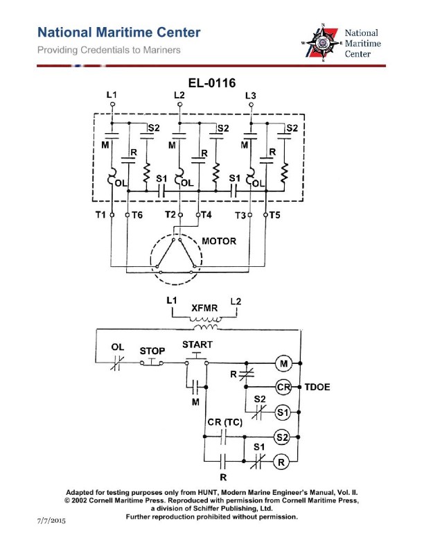
Question 239
Question: As shown in the illustrated three-phase squirrel cage induction motor controller, what type of reduced voltage starter is used? Illustration EL-0116
A. wye-delta starter with a closed transition
B. wye-delta starter with an open transition
C. delta-wye starter with an open transition
D. delta-wye starter with a closed transition
The correct answer is A) wye-delta starter with a closed transition. A wye-delta starter is a type of reduced voltage starter used to gradually apply full voltage to an induction motor. The "closed transition" refers to the method of switching from the wye configuration to the delta configuration, where the motor windings are briefly connected in both configurations during the transition to avoid an abrupt voltage change. The other options are incorrect because: B) A wye-delta starter with an open transition would have a brief interruption in the motor supply during the transition, which is not the case here. C) A delta-wye starter is the reverse configuration and is not typically used. D) A delta-wye starter with a closed transition is not a common configuration for induction motor starters.
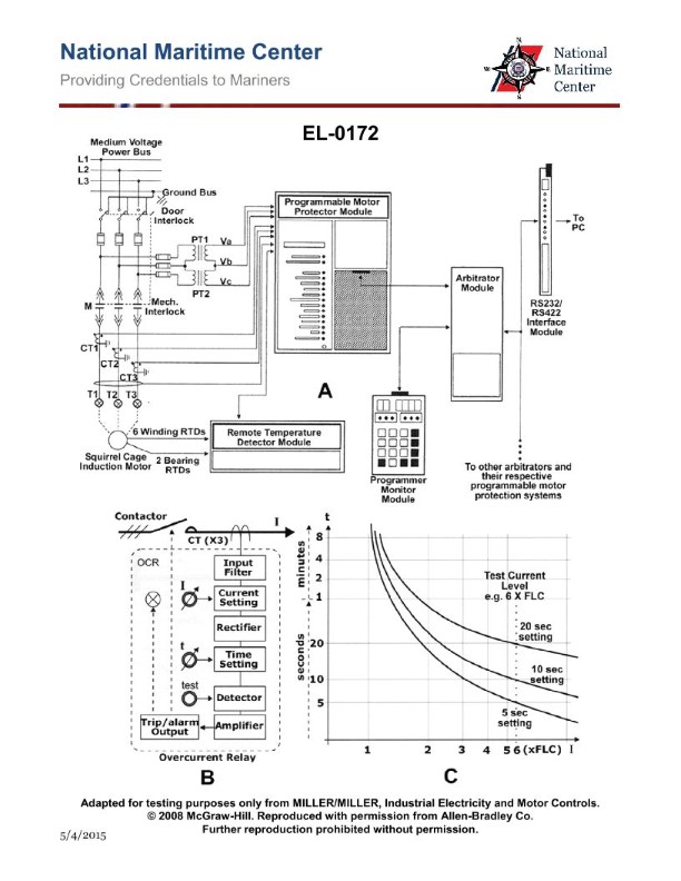
Question 240
Question: As shown in figure "B" of the illustration, what type of overload relay for motor protection is illustrated? EL-0172
A. Electronic
B. Thermal solder-pot
C. Thermal bimetallic
D. Electromagnetic
The correct answer is A) Electronic. The illustration in figure "B" shows an electronic overload relay for motor protection, which is typically an electronic device that monitors the current draw of the motor and trips when the current exceeds a preset limit, providing thermal overload protection for the motor. Electronic overload relays are commonly used in modern motor control systems and are preferred over the other options listed, such as thermal solder-pot or bimetallic relays, due to their increased accuracy and responsiveness. The other answer choices, B) Thermal solder-pot and C) Thermal bimetallic, are types of overload relays that use thermal principles to sense overload conditions, but they are less common in modern applications and are not depicted in the illustration provided.
Question 241
Question: What type of control circuit logic is featured in the electrical schematic diagram for the motor starting circuit shown in figure "B" of the illustration? EL-0007
A. low voltage release
B. low voltage protection
C. reduced voltage starting
D. resistance starting
The correct answer is B) low voltage protection. The low voltage protection circuit is a type of control circuit logic that is designed to prevent the motor from starting or continuing to run if the voltage supply drops below a certain threshold. This is an important safety feature to prevent damage to the motor or other electrical components in the event of a voltage drop or brownout. The other answer choices are not correct in this context. Low voltage release is a different type of circuit that disconnects the motor from the power supply if the voltage drops. Reduced voltage starting and resistance starting refer to methods of starting the motor, not the control circuit logic.
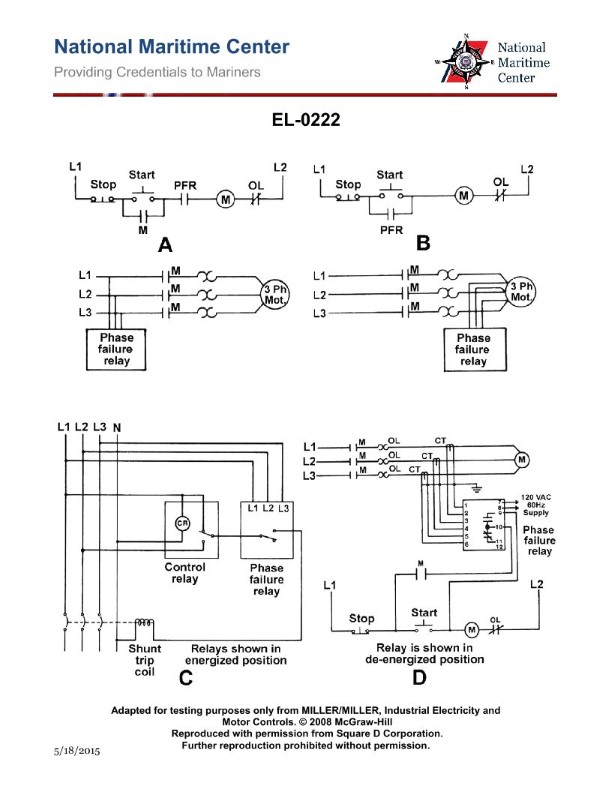
Question 242
Question: Which of the following illustrated circuit schematics provides phase failure protection for a three phase motor using load side current sensing technology? Illustration EL-0222
A. A
B. B
C. C
D. D
The correct answer is D. The illustrated circuit schematic labeled EL-0222 option D provides phase failure protection for a three-phase motor using load-side current sensing technology. This type of protection monitors the current in each phase of the motor and can detect the loss of one or more phases, which can cause damage to the motor. By using load-side sensing, the circuit can directly measure the current being drawn by the motor and take appropriate action to shut down the motor in the event of a phase failure. The other answer choices (A, B, and C) do not provide the same level of phase failure protection or may use different sensing methods, making them incorrect for this specific application.
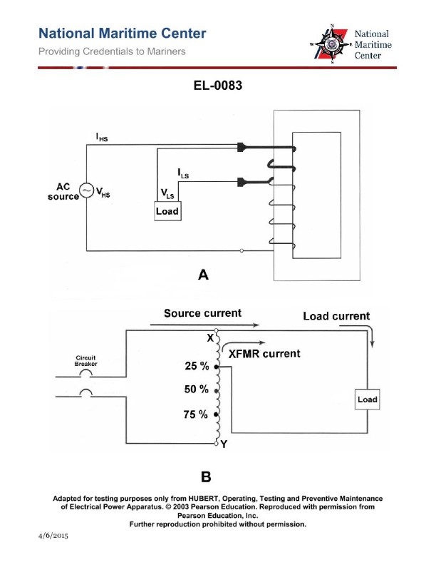
Question 274
Question: What is the device shown in figure "B" of the illustration between the source circuit breaker and the load? Illustration EL-0083
A. fluorescent light ballast
B. power factor correction inductor
C. autotransformer
D. noise filtering choke
The correct answer is C) autotransformer. An autotransformer is a type of electrical transformer that uses a single winding to step up or step down the voltage. In the illustration EL-0083, the device shown in figure "B" between the source circuit breaker and the load is an autotransformer, which is used to adjust the voltage level as needed for the load. The other answer choices are incorrect because a fluorescent light ballast (A) is used to regulate the current in a fluorescent light, a power factor correction inductor (B) is used to improve the power factor of the circuit, and a noise filtering choke (D) is used to reduce electrical noise or interference, rather than adjusting the voltage level.
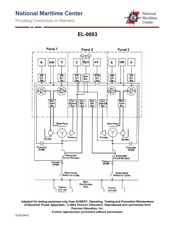
Question 275
Question: In the illustrated switchboard, what is the purpose of the device labeled "AM Sel. Sw."? Illustration EL-0003
A. it allows the instantaneous difference between individual three phase legs to be displayed on the ammeter
B. it allows the instantaneous average of the three phase legs of alternator current to be displayed on the ammeter
C. it allows the instantaneous difference between the average of the three phase legs of both alternators to be compared
D. it allows the individual three phase legs of alternator current to be displayed on the ammeter by selective switching
The correct answer is D) it allows the individual three phase legs of alternator current to be displayed on the ammeter by selective switching. The "AM Sel. Sw." or Ammeter Selector Switch allows the operator to select which individual phase of the three-phase alternator current is displayed on the ammeter. This allows the operator to monitor the current in each phase independently, which is important for identifying any imbalances or issues with the alternator system. The other answer choices do not accurately describe the function of this selector switch.
Question 276
Question: What do the devices labeled "L" in Panel 2 of the illustrated switchboard represent? Illustration EL-0003
A. power available lights indicating that the generator is producing a voltage
B. load lights indicating that the generator breaker is closed and the generator is supplying power to the main bus
C. emergency lighting for the switchboard to enable the meters to be read in case of power failure
D. synchronizing lights used as a backup to the synchroscope for paralleling purposes
The correct answer is D) synchronizing lights used as a backup to the synchroscope for paralleling purposes. The devices labeled "L" in Panel 2 of the illustrated switchboard represent synchronizing lights, which are used as a backup to the synchroscope for the purpose of paralleling generators. Synchronizing lights allow the operator to visually confirm that the incoming generator's voltage, frequency, and phase are aligned with the running generator before closing the breaker to parallel the two. This is a standard practice required by Coast Guard regulations to ensure the safe and proper paralleling of generators on a switchboard. The other answer choices are incorrect because they do not accurately describe the purpose of the "L" labeled devices in the context of a marine switchboard. Power available lights, load lights, and emergency lighting serve different functions that are not relevant to the synchronization of generators.
Question 277
Question: As shown in the illustrated switchboard, what is the function of the switch labeled 'PFM Sel. Sw.'? Illustration EL-0003
A. to determine bus frequency
B. to determine reactive volt amperes of the bus
C. to determine frequency of either generator
D. to determine power factor of either generator
The correct answer is D) to determine power factor of either generator. The "PFM Sel. Sw." or Power Factor/Megawatt Selector Switch is used to determine the power factor of the generators connected to the switchboard. This is an important parameter to monitor, as the power factor affects the efficiency and performance of the electrical system. The other answer choices are incorrect because they do not accurately describe the function of this particular switch. Options A and C relate to frequency, while option B is about reactive volt-amperes, which are different electrical parameters from power factor.
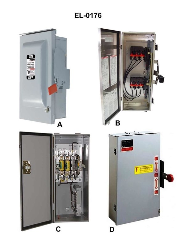
Question 278
Question: Which of the illustrated safety disconnect switches represents a double throw switch? Illustration EL-0176
A. A and B
B. B and D
C. C and D
D. A and D
The correct answer is B) B and D. The double throw switch is represented by the switch labeled "B" and the switch labeled "D" in the illustration EL-0176. A double throw switch is a type of electrical switch that can connect a circuit to one of two different circuits, effectively allowing the circuit to be "thrown" or switched between the two different options. The other answer choices are incorrect because they do not correctly identify the double throw switch in the illustration. Option A (A and B) is incorrect because only the switch labeled "B" is a double throw switch. Option C (C and D) is incorrect because the switch labeled "C" is not a double throw switch. Option D (A and D) is incorrect because the switch labeled "A" is not a double throw switch.