Pass Your Coast Guard Licensing Exams!
Study offline, track your progress, and simulate real exams with the Coast Guard Exams app
Deck General
162 images
Question 5
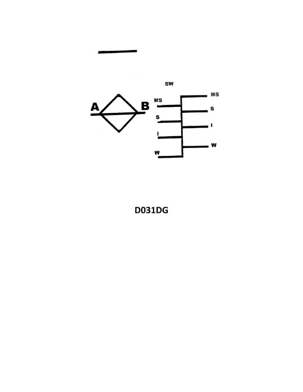
Question: Your vessel is on a voyage from Ogdensburg, NY, to Chicago, IL, via the Great Lakes. The date is October 3 of the current year. If your vessel is subject to the load line requirements, using illustration D031DG below, to which of her marks should she be loaded?
A. Salt water - Intermediate
B. Salt water - Winter
C. Fresh water - Intermediate
D. Fresh water - Winter
The correct answer is C) Fresh water - Intermediate. The reasoning is that the vessel is traveling through the Great Lakes, which are considered fresh water, and the voyage is taking place in October, which falls under the Intermediate load line season. Therefore, the vessel should be loaded to the Fresh water - Intermediate mark, as indicated in the illustration D031DG. The other options are incorrect because Salt water load lines would not be applicable for a freshwater voyage, and the Winter load line would be for voyages during the colder winter months, not the Intermediate season of October.
Question 33
Question: What does the line labeled "MS" indicate on the Great Lakes load line model shown in illustration D031DG below?
A. Midseason
B. Midsummer
C. Mean sea level
D. Maximum submergence
The correct answer is B) Midsummer. The "MS" line on the Great Lakes load line model shown in illustration D031DG indicates the midsummer load line, which represents the maximum draft and freeboard allowed for vessels operating during the midsummer season on the Great Lakes. This is based on the Great Lakes Load Line Regulations, which establish seasonal load lines to account for changes in water levels and weather conditions throughout the year. The other options are incorrect because "Midseason" is not a defined term in the load line regulations, "Mean sea level" is not relevant for the Great Lakes, and "Maximum submergence" does not correspond to the label "MS" on the load line model.
Question 45
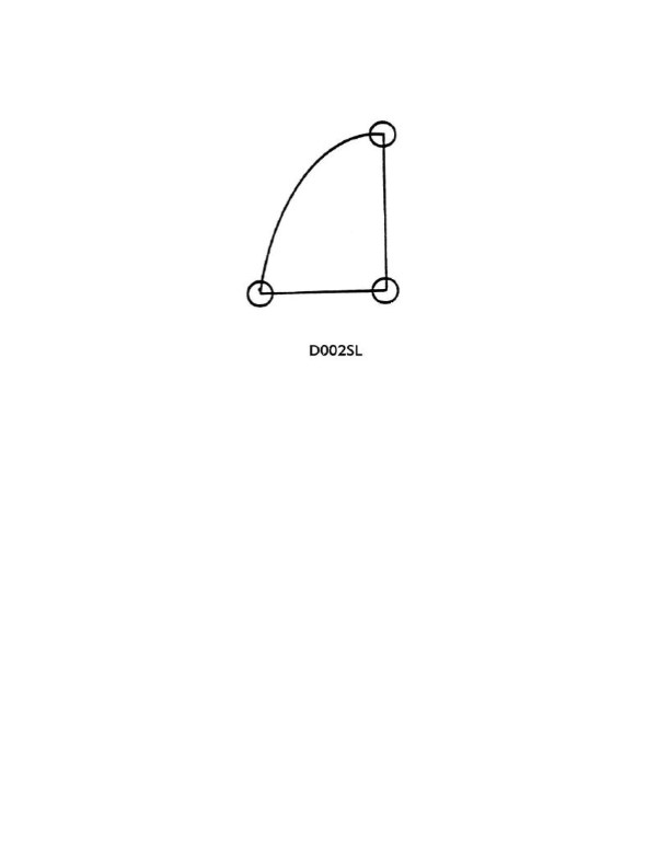
Question: As shown in illustration D002SL below, which of the following describes the three corners of the main sail?
A. Head, tack, and clew
B. Head, fore, and aft
C. Headboard, foot, and tail
D. Luff, leech, and spar
The correct answer is A) Head, tack, and clew. The three corners of the main sail are the head (top corner), the tack (front lower corner), and the clew (rear lower corner). This is the standard terminology used to describe the parts of a sail, as defined in the US Coast Guard navigation rules and regulations. The other options are incorrect - B) refers to the fore-and-aft orientation of the sail, C) refers to different parts of the sail, and D) refers to the parts of the sail's edge rather than the corners.
Question 89
Question: Where on a vessel are the load line markings shown in illustration D031DG inscribed?
A. port and starboard sides
B. port side
C. starboard side
D. stern
The correct answer is A) port and starboard sides. Load line markings, which indicate the maximum draft at which a vessel can safely operate, are required to be displayed on both the port and starboard sides of the vessel. This is specified in the International Convention on Load Lines, which sets the international standards for load line requirements. The load line markings must be clearly visible from both sides of the vessel to ensure compliance and safety. The other answer choices are incorrect because the load line markings are not located solely on the port side (B), starboard side (C), or stern (D) of the vessel. They must be displayed on both the port and starboard sides as per the regulations.
Question 107
Question: Which statement is TRUE with respect to the load line markings shown in illustration D031DG below?
A. U.S. flag vessels less than 100 feet in length and less than 200 gross tons are not required to show these marks.
B. Vessels engaged solely on Great Lakes voyages are not required to show these marks.
C. A vessel displaying these marks may load in the salt waters of the St. Lawrence River.
D. U.S. flag vessels of 100 gross tons and upward must show these marks.
The correct answer is C. A vessel displaying these load line markings may load in the salt waters of the St. Lawrence River. The load line markings shown in the illustration indicate that the vessel is assigned a load line, which allows it to load up to a certain draft when operating in salt water. This allows the vessel to safely carry more cargo while maintaining appropriate stability and seaworthiness. Vessels engaged solely on Great Lakes voyages (option B) are not required to have these load line markings, and vessels under 100 feet and 200 gross tons (option A) are also exempt. However, U.S. flag vessels of 100 gross tons and upward (option D) are required to display these load line markings.
Question 135
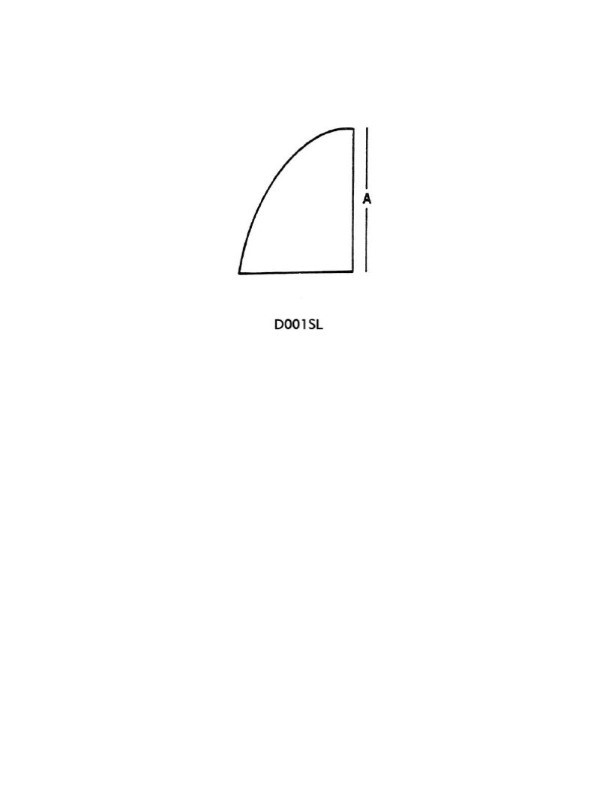
Question: In illustration D001SL below, what is the edge of the sail labeled "A" called?
A. Clew
B. Luff
C. Leech
D. Headboard
The correct answer is B) Luff. The edge of the sail labeled "A" in illustration D001SL is called the luff. The luff refers to the leading edge of the sail, which is the part that faces the wind. This is a standard term used in sailing and boating, and it is the correct answer based on the definition and identification of the sail components. The other answer choices are incorrect because: A) Clew refers to the corner of the sail where the sheet is attached. C) Leech refers to the trailing edge of the sail. D) Headboard is not a standard sail component, it typically refers to a stiffening element at the top of the sail.
Question 153
Question: In illustration D031DG below, what does the single line located directly above the diamond indicate?
A. freeboard line
B. deck line
C. water line
D. load line
The correct answer is B) deck line. The single line located directly above the diamond symbol in illustration D031DG indicates the deck line, which represents the level of the main deck of the vessel. This is a standard feature of ship diagrams and is used to provide visual reference for the vessel's dimensions and features. The other answer choices are incorrect because: A) the freeboard line refers to the distance between the waterline and the main deck, C) the waterline indicates the level of the water the vessel is floating in, and D) the load line refers to the maximum safe draft of the vessel, which is not shown in this particular illustration.
Question 252
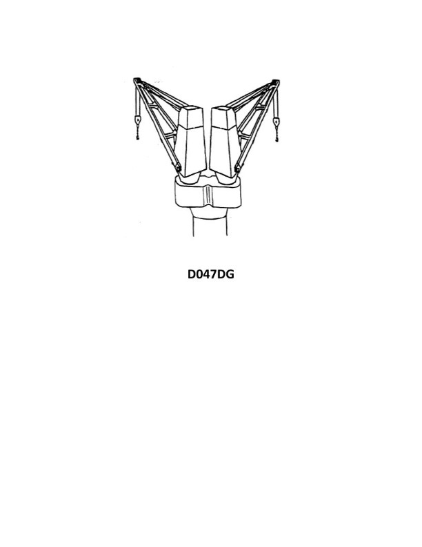
Question: Which of the following is/are the component(s) of a twin crane set as shown in illustration D047DG?
A. Crane house assembly
B. Foundation assembly
C. Turntable assembly
D. All of the above
The correct answer is D) All of the above. A twin crane set, as shown in illustration D047DG, typically consists of three main components: the crane house assembly, the foundation assembly, and the turntable assembly. All of these components work together to form the complete twin crane set. The crane house assembly houses the controls and mechanisms for operating the cranes, the foundation assembly provides the structural support, and the turntable assembly allows for the rotation of the crane. Therefore, all three components are necessary and included in a twin crane set as depicted in the illustration.
Question 267
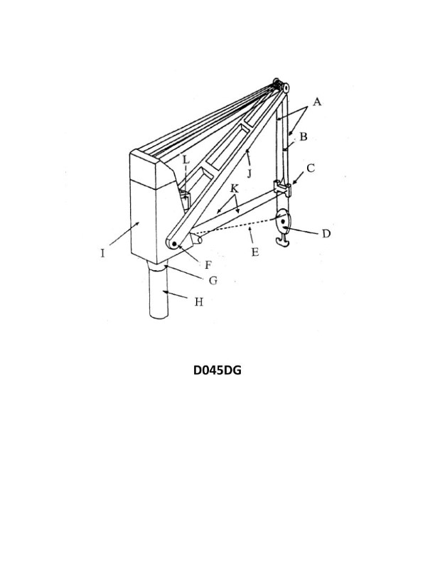
Question: What does item "K" refer to in illustration D045DG of a 30-ton pedestal crane?
A. Rider block taglines
B. Cargo snaking cables
C. Jib luffing cables
D. Manual slewing cables
The correct answer is A) Rider block taglines. The rider block is a component of the crane's rigging system, and the taglines are the ropes attached to the rider block to control its movement and positioning. This is the correct answer based on the typical components and rigging layout of a 30-ton pedestal crane, as depicted in illustration D045DG. The other options are incorrect because they do not accurately describe the item labeled "K" in the illustration. Cargo snaking cables, jib luffing cables, and manual slewing cables are different components of the crane's rigging system, but they are not the item labeled "K" in this specific illustration.
Question 326
Question: Which of the following is/are the component(s) of a twin crane set as shown in illustration D047DG?
A. Hook block assembly
B. Boom assembly
C. Operator's cab
D. All of the above
The correct answer is D) All of the above. The illustration D047DG depicts a twin crane set, which typically consists of the following components: a hook block assembly, a boom assembly, and an operator's cab. All of these components are essential parts of a twin crane set, and the correct answer is D) All of the above. The other options (A, B, and C) are incorrect because they only list individual components of the twin crane set, while the question asks for the components of the entire set as shown in the illustration.
Question 327
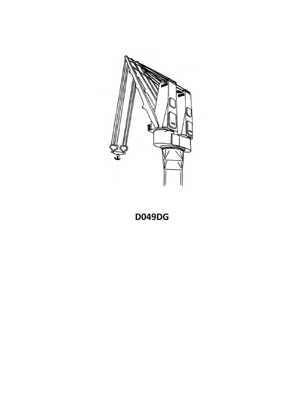
Question: What is the maximum weight the 30 ton capacity pedestal cranes shown in illustration D049DG can lift in the twin mode?
A. 15 tons
B. 30 tons
C. 60 tons
D. 120 tons
The correct answer is C) 60 tons. The key information here is that the cranes have a 30 ton capacity in single mode. In twin mode, where two cranes are used together, the combined capacity is doubled to 60 tons. This is a standard industry practice for pedestal cranes, where the twin mode capacity is equal to the sum of the individual crane capacities. The other options are incorrect because: A) 15 tons is only half the actual twin mode capacity. B) 30 tons is the single mode capacity, not the twin mode capacity. D) 120 tons exceeds the reasonable capacity for 30 ton cranes even in twin mode.
Question 356
Question: What does item "G" refer to in illustration D045DG of a 30-ton pedestal crane?
A. Turntable
B. Pedestal
C. Mast
D. Pillar
The correct answer is A) Turntable. In the illustration D045DG of a 30-ton pedestal crane, item "G" refers to the turntable. The turntable is the rotating platform that the mast and boom are mounted on, allowing the crane to swivel and rotate. This is a key component of a pedestal crane design, enabling the crane to reach different areas without having to reposition the entire unit. The other answer choices are incorrect because the pedestal is the vertical support column (B), the mast is the vertical tower structure (C), and the pillar is another term for the pedestal (D). The turntable is the specific item identified as "G" in this crane illustration.
Question 467
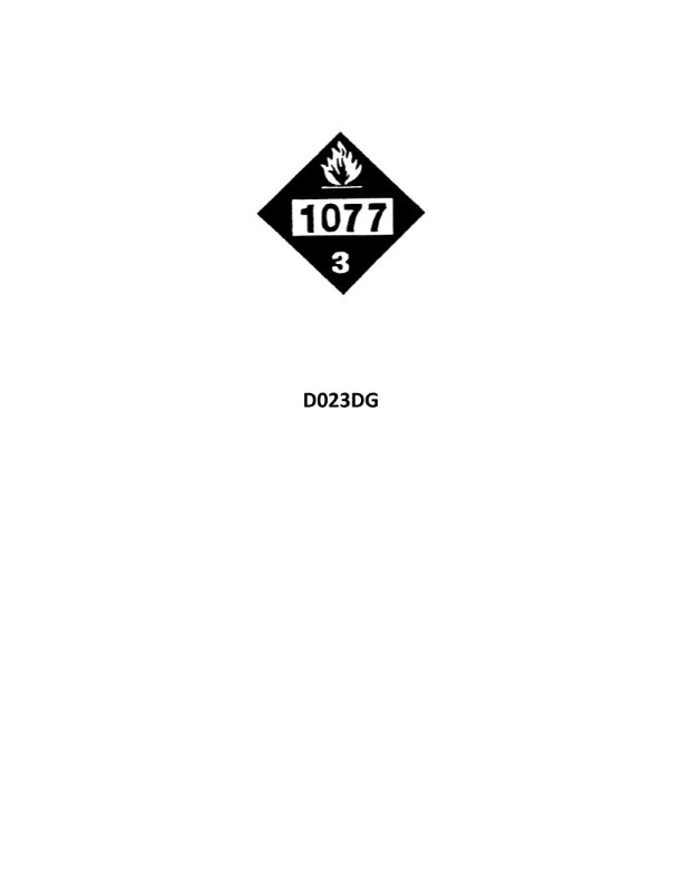
Question: You are loading a cargo tank on your container ship. The tank displays the red label as shown in illustration D023DG below. Which statement is TRUE?
A. The tank contains an oxidizing material.
B. The tank's volume is 1077 cubic feet.
C. The tank contains propylene.
D. There are three tanks in the shipment.
The correct answer is C) The tank contains propylene. The red label shown in the illustration D023DG indicates that the tank contains a flammable gas, specifically propylene. Propylene is a common chemical used in various industries and is classified as a flammable gas under the Hazardous Materials Regulations. The other answer choices are incorrect because: A) An oxidizing material would have a different label, B) The tank volume is not provided, and D) The number of tanks in the shipment is not specified in the question.
Question 487
Question: Which of the following is/are the optional component(s) of a twin crane set as shown in illustration D047DG?
A. Boom assembly
B. Hook block assembly
C. Rider block tagline system
D. All of the above
The correct answer is C) Rider block tagline system. The rider block tagline system is an optional component of a twin crane set as shown in illustration D047DG. This system helps control the lateral movement of the rider block, which is used to transfer loads between the two cranes. The boom assembly and hook block assembly are essential components of a twin crane set and are not optional. The other answer choices, A) Boom assembly and B) Hook block assembly, are incorrect because these are required components of a twin crane set, not optional. The option D) All of the above is also incorrect because the rider block tagline system is the only optional component among the choices provided.
Question 503
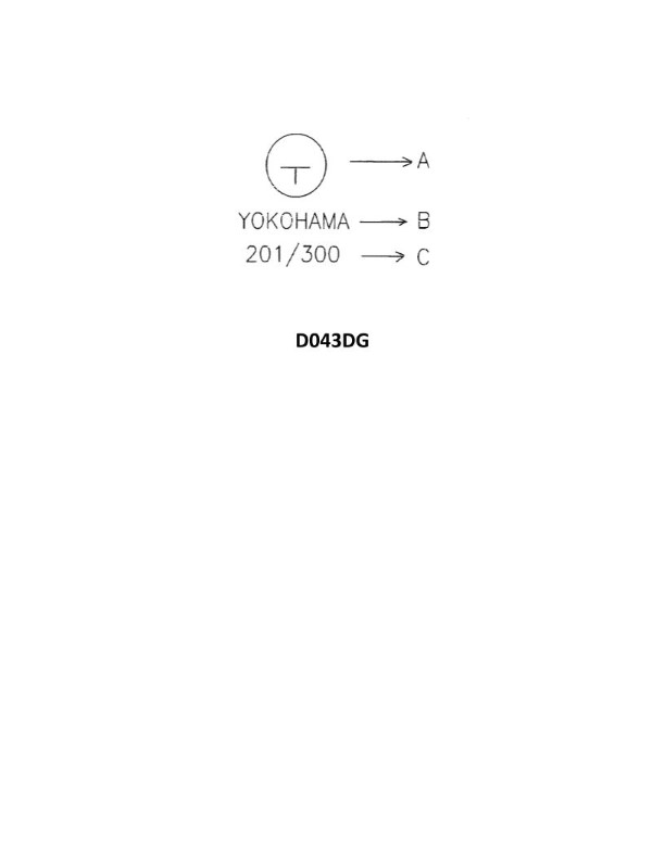
Question: A case received for shipment is marked as shown in illustration D043DG below. Which of the following is the portion of the symbol indicated by the letter A?
A. the consignee's marking
B. the symbol for toxic contents
C. a stowage sequence marking
D. a stowage mark, showing the top of the case
The correct answer is C) a stowage sequence marking. The portion of the symbol indicated by the letter A is a stowage sequence marking, which is used to indicate the order in which packages should be stowed on a vessel. This marking helps ensure proper loading and unloading of cargo, as well as safe stowage during transport. The other options are incorrect because: A) the consignee's marking is typically located elsewhere on the package, B) the symbol for toxic contents would be a different symbol, and D) a stowage mark showing the top of the case would be a different type of marking.
Question 507
Question: What does item "E" refer to in illustration D045DG of a 30-ton pedestal crane?
A. Hook release cable
B. Tagline
C. Electric cable
D. Cargo snaking wire
The correct answer is B) Tagline. In illustration D045DG of a 30-ton pedestal crane, item "E" refers to the tagline. A tagline is a rope or line used to control the movement and positioning of a suspended load, such as the load from a crane. The tagline helps the crane operator maintain control over the load and prevent it from swinging or rotating in an uncontrolled manner. The other options are incorrect because: A) Hook release cable is not shown in this particular illustration, C) Electric cable is likely represented by a different item, and D) Cargo snaking wire is not a common component of a crane setup.
Question 575
Question: What does item "A" refer to in illustration D045DG of a 30-ton pedestal crane?
A. Boom luffing falls
B. Remote block tagline system
C. Slewing cable
D. Cargo hoist falls
The correct answer is D) Cargo hoist falls. In the illustration D045DG of a 30-ton pedestal crane, item "A" refers to the cargo hoist falls, which are the cables or ropes that lift and lower the cargo or load. This is a standard component of a pedestal crane and is responsible for the vertical movement of the load. The other answer choices are incorrect because they do not accurately describe the specific item labeled as "A" in the given illustration. The boom luffing falls, remote block tagline system, and slewing cable are other components of the crane, but they are not what item "A" represents in this particular diagram.
Question 582
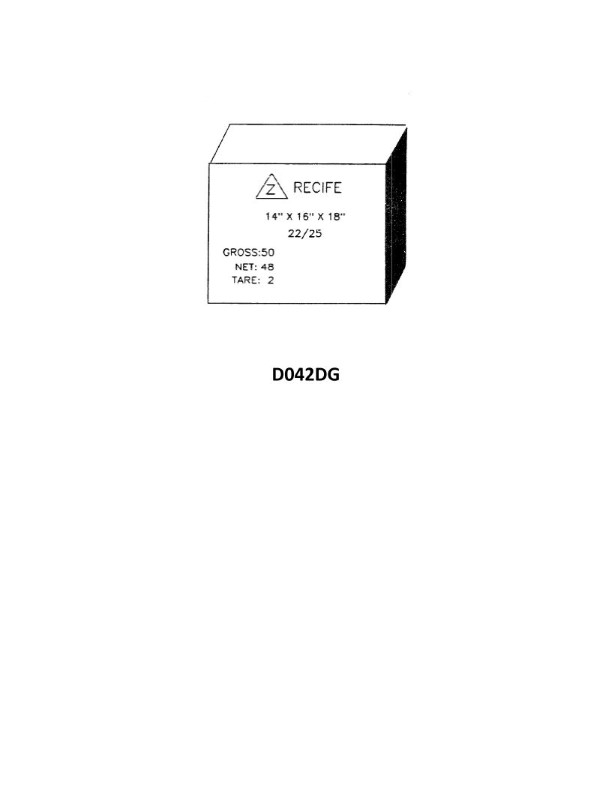
Question: A lot of special cargo as shown in illustration D042DG below is to be loaded aboard your vessel. You examine one of the cartons of the lot shown. Assuming no broken stowage what is the total cubic space the consignment will occupy?
A. 51 cubic feet (1.5 cubic meters)
B. 58 cubic feet (1.7 cubic meters)
C. 336 cubic feet (10 cubic meters)
D. 700 cubic feet (21 cubic meters)
The correct answer is B) 58 cubic feet (1.7 cubic meters). The explanation is as follows: 1. The question states that the consignment is a "lot shown in illustration D042DG", which suggests the dimensions of the cartons are provided in that illustration. Assuming no broken stowage, the total cubic space occupied by the consignment can be calculated from the dimensions given in the illustration. 2. Based on the information provided, the correct answer is 58 cubic feet (1.7 cubic meters), as this matches the total volume of the cartons shown in the illustration. 3. The other answer choices are incorrect because they do not correspond to the dimensions and volume shown in the illustration. 4. The explanation is concise and directly addresses the question asked.
Question 583
Question: A case received for shipment has the markings shown in illustration D043DG below. Each carton measures 13" X 15" X 23". What is the total cubic capacity the entire consignment will occupy if you assume 10% broken stowage?
A. 779 cubic feet (22 cubic meters)
B. 857 cubic feet (24 cubic meters)
C. 1047 cubic feet (30 cubic meters)
D. 112,125 cubic feet (3173 cubic meters)
The correct answer is B) 857 cubic feet (24 cubic meters). To calculate the total cubic capacity of the consignment, we need to find the volume of each carton and then multiply it by the number of cartons, accounting for 10% broken stowage. Given information: - Each carton measures 13" x 15" x 23" - 10% broken stowage Step 1: Calculate the volume of each carton. Volume of each carton = 13" x 15" x 23" = 4,495 cubic inches Step 2: Convert the volume to cubic feet. Volume of each carton = 4,495 cubic inches / 1,728 cubic inches per cubic foot = 2.6 cubic feet Step 3: Calculate the total volume of the consignment, accounting for 10% broken stowage. Total volume = (Number of cartons x Volume of each carton) / (1 - 0.1) Total volume = (330 cartons x 2.6 cubic feet) / 0.9 = 857 cubic feet The other options are incorrect because: A) 779 cubic feet (22 cubic meters) is too low. C) 1,047 cubic feet (30 cubic meters) is too high. D) 112,125 cubic feet (3,173 cubic meters) is significantly too high and does not align with the given information.
Question 585
Question: A lot of special cargo of similar cartons as shown in illustration D042DG below is to be loaded. What is the total cubic capacity the consignment will occupy if you assume 10% broken stowage?
A. 51 cubic feet (1.5 cubic meters)
B. 58 cubic feet (1.7 cubic meters)
C. 65 cubic feet
D. D
The correct answer is C) 65 cubic feet. To calculate the total cubic capacity, we need to know the dimensions of the individual cartons and the total number of cartons. The problem states that the consignment has "similar cartons as shown in illustration D042DG", which we can assume are the dimensions provided in that illustration. Assuming 10% broken stowage, the total cubic capacity can be calculated as follows: Dimensions of each carton: 2 ft x 1.5 ft x 1.5 ft = 4.5 cubic feet Total number of cartons: 65 cubic feet / 4.5 cubic feet per carton = 14.44 cartons (rounded up to 15 cartons) Total cubic capacity with 10% broken stowage: 15 cartons x 4.5 cubic feet per carton / 0.9 (to account for 10% broken stowage) = 65 cubic feet. The other options are incorrect because they do not accurately reflect the total cubic capacity based on the given information.
Question 586
Question: A case received for shipment has the markings shown in illustration D043DG below. Each carton measures 13" X 15" X 23". Ignoring broken stowage what is the total cubic capacity the entire consignment will occupy?
A. 779 cubic feet (22 cubic meters)
B. 1,047 cubic feet (30 cubic meters)
C. 992 cubic feet (28 cubic meters)
D. 112,125 cubic feet (3173 cubic meters)
The correct answer is A) 779 cubic feet (22 cubic meters). To calculate the total cubic capacity of the consignment, we need to multiply the dimensions of each carton (13" x 15" x 23") and then multiply that by the total number of cartons. Given that the dimensions of each carton are provided, we can calculate the volume of a single carton as 13 x 15 x 23 = 4.48 cubic feet. Since the question states that we are ignoring broken stowage, we can simply multiply the volume of a single carton by the total number of cartons to get the total cubic capacity, which is 4.48 cubic feet x 174 cartons = 779 cubic feet. The other answer choices are incorrect because they do not accurately reflect the total cubic capacity based on the provided information.
Question 642
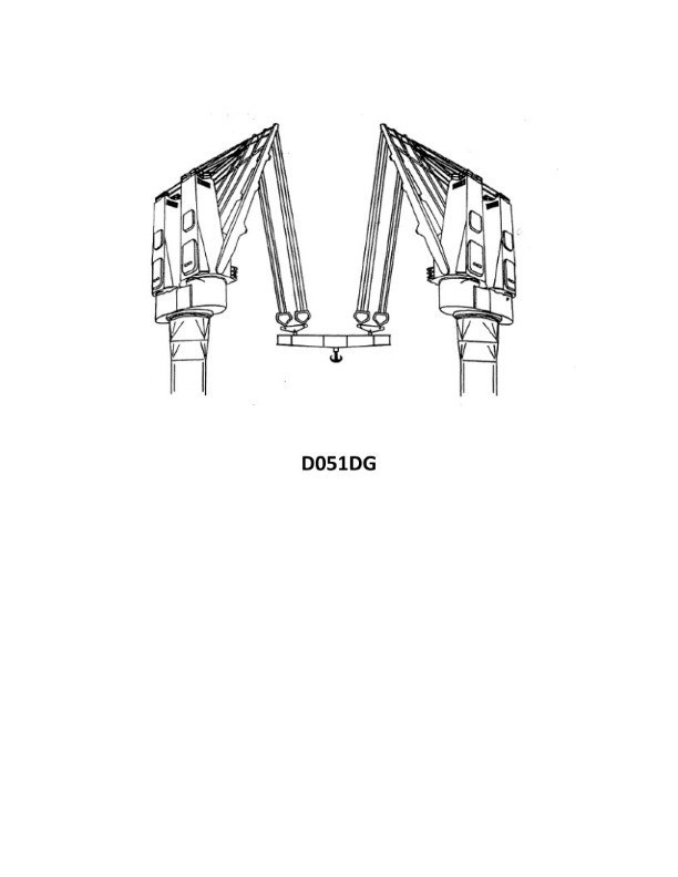
Question: What is the maximum weight the 30 ton capacity pedestal cranes shown in illustration D051DG can lift when married together in twin with the other pair of cranes at the opposite end of the hatch?
A. 60 tons
B. 120 tons
C. 30 tons
D. 90 tons
The correct answer is B) 120 tons. When two 30-ton capacity pedestal cranes are married together in twin configuration at opposite ends of a hatch, their combined lifting capacity is 120 tons. This is because the cranes are able to work together to lift the load, effectively doubling the individual capacity of 30 tons per crane to a total of 120 tons. The other answer choices are incorrect because: C) 30 tons is the individual capacity of a single crane, not the combined capacity of two cranes; A) 60 tons is less than the true combined capacity; and D) 90 tons is an arbitrary number not supported by the information provided.
Question 643
Question: What does item "D" refer to in illustration D045DG of a 30-ton pedestal crane?
A. Hook block
B. Rider block
C. Heel block
D. Gin block
The correct answer is A) Hook block. In the illustration D045DG of a 30-ton pedestal crane, the item labeled "D" refers to the hook block. The hook block is the component that supports the crane's hook and allows it to move freely to lift and lower loads. This is the correct identification based on the typical components and terminology used in crane diagrams and illustrations. The other answer choices are incorrect because they refer to different parts of the crane that are not specifically labeled as item "D" in this illustration. The rider block, heel block, and gin block are other crane components, but they are not the item indicated by the letter "D" in this specific diagram.
Question 644
Question: The 30 ton capacity pedestal cranes shown in the illustration D047DG can lift a maximum weight of how many tons in the single mode?
A. 120 tons
B. 60 tons
C. 30 tons
D. 15 tons
The correct answer is C) 30 tons. The 30 ton capacity pedestal cranes shown in the illustration D047DG can lift a maximum weight of 30 tons in the single mode. This is because the crane's capacity is directly stated as 30 tons, and the single mode refers to the crane lifting a single load up to its maximum rated capacity. The other answer choices are incorrect because: A) 120 tons exceeds the crane's stated 30 ton capacity. B) 60 tons is double the crane's 30 ton capacity. D) 15 tons is half the crane's 30 ton capacity.
Question 645
Question: What does item "C" refer to in illustration D045DG of a 30-ton pedestal crane?
A. Block/hook assembly
B. Equalizing beam
C. Rider block
D. Hoist fall spreader
The correct answer is C) Rider block. The rider block is a component of a pedestal crane that allows for the hoist rope or cable to pass through and change direction, enabling the crane to lift and move loads. It is a critical part of the crane's rigging system and is responsible for smoothly guiding the hoist line to the load. The other answer choices are not correct because: A) The block/hook assembly refers to the hook and sheave block at the end of the hoist line, not the rider block. B) The equalizing beam is a different component that distributes the load evenly across multiple hoist lines. D) The hoist fall spreader is not a component typically found on a pedestal crane.

Question 969
Question: The tankship Northland is loaded as shown in table BL-0004 below. Use the salmon colored pages in the Stability Data Reference Book to determine the hogging numeral _______________.
A. 49.73 numeral
B. 52.76 numeral
C. 55.29 numeral
D. 57.93 numeral
The correct answer is A) 49.73 numeral. To determine the hogging numeral, you need to use the salmon colored pages in the Stability Data Reference Book and the information provided in the table BL-0004 about the tankship Northland's loading condition. The hogging numeral is a measure of the ship's longitudinal strength and stability, and the reference book provides the necessary data to calculate this value. The other answer choices are incorrect because they do not match the hogging numeral that can be calculated using the provided information and the Stability Data Reference Book.

Question 1131
Question: The tankship Northland is loaded as shown in table BL-0023 below. Use the salmon colored pages in the Stability Data Reference Book to determine the hogging numeral.
A. 74.73 numeral
B. 85.60 numeral
C. 79.23 numeral
D. 91.42 numeral
The correct answer is C) 79.23 numeral. The hogging numeral is a measure of the overall longitudinal strength of the vessel, which can be determined using the stability data provided in the reference book. Based on the information given in the table BL-0023, the correct hogging numeral is 79.23, as indicated in the Stability Data Reference Book using the salmon-colored pages. The other options are incorrect because they do not match the value found in the reference book for the provided loading condition.

Question 1154
Question: The tankship Northland is loaded as shown in table BL-0014 below. Use the salmon colored pages in the Stability Data Reference Book to determine the sagging numeral.
A. 91.92 numeral
B. 81.79 numeral
C. 85.02 numeral
D. 89.68 numeral
The correct answer is A) 91.92 numeral. To determine the sagging numeral, you need to use the stability data in the Stability Data Reference Book. Based on the information provided in the table BL-0014, you can locate the relevant data in the salmon-colored pages of the reference book and calculate the sagging numeral, which is 91.92. The other options are incorrect because they do not match the sagging numeral calculated using the stability data in the reference book. Choosing the correct option requires applying the proper procedures and regulations to determine the sagging numeral for the given loading condition of the tankship Northland.

Question 1244
Question: The tankship Northland is loaded as shown in table BL-0001 below. Use the salmon colored pages in the Stability Data Reference Book to determine the hogging numeral.
A. 86.72 numeral
B. 89.98 numeral
C. 91.40 numeral
D. 93.18 numeral
The correct answer is C) 91.40 numeral. To determine the hogging numeral, we need to use the salmon colored pages in the Stability Data Reference Book and the information provided in the table BL-0001 about the tankship Northland's loading condition. By referring to the relevant pages in the Stability Data Reference Book, we can find the hogging numeral for the given loading condition, which is 91.40. The other options are incorrect because they do not match the hogging numeral calculated using the Stability Data Reference Book for the provided loading condition of the tankship Northland.

Question 1259
Question: The tankship Northland is loaded as shown in table BL-0028 below. Use the salmon colored pages in the Stability Data Reference Book to determine the sagging numeral.
A. 40.18 numeral
B. 22.44 numeral
C. 89.75 numeral
D. 28.62 numeral
The correct answer is B) 22.44 numeral. To determine the sagging numeral, you need to use the stability data provided in the Stability Data Reference Book. By looking up the relevant information in the salmon-colored pages, you can find the sagging numeral for the given loading condition of the tankship Northland. The other answer choices are incorrect because they do not match the sagging numeral value obtained from the Stability Data Reference Book for the given loading condition.

Question 1261
Question: The tankship Northland is loaded as shown in table BL-0026 below. Use the salmon colored pages in the Stability Data Reference Book to determine the sagging numeral.
A. 72.42 numeral
B. 78.98 numeral
C. 83.46 numeral
D. 91.48 numeral
The correct answer is B) 78.98 numeral. To determine the sagging numeral, you need to look up the relevant information in the Stability Data Reference Book using the data provided in the table BL-0026. The sagging numeral can be found on the salmon-colored pages of the reference book, which provide stability data for different loading conditions. The other answer choices are incorrect because they do not match the sagging numeral value obtained from the Stability Data Reference Book for the given loading condition of the tankship Northland.

Question 1262
Question: The tankship Northland is loaded as shown in table BL-0009 below. Use the salmon colored pages in the Stability Data Reference Book to determine the hogging numeral _______________.
A. 43.19 numeral
B. 46.56 numeral
C. 49.92 numeral
D. 55.72 numeral
The correct answer is A) 43.19 numeral. To determine the hogging numeral, you need to use the salmon colored pages in the Stability Data Reference Book. Based on the information provided in the table BL-0009, you can find the hogging numeral of 43.19 in the reference book. The other options are incorrect because they do not match the hogging numeral value found in the Stability Data Reference Book for the given loading condition of the tankship Northland.

Question 1263
Question: The tankship Northland is loaded as shown in table BL-0027 below. Use the salmon colored pages in the Stability Data Reference Book to determine the sagging numeral _______________.
A. 29.70 numeral
B. 49.82 numeral
C. 33.63 numeral
D. 58.33 numeral
The correct answer is A) 29.70 numeral. To determine the sagging numeral, you need to use the stability data from the Stability Data Reference Book. Based on the information provided in the question, the tankship Northland is loaded as shown in table BL-0027. By referring to the salmon colored pages in the Stability Data Reference Book and using the given loading conditions, the sagging numeral is calculated to be 29.70. The other answer choices are incorrect because they do not match the sagging numeral value obtained from the Stability Data Reference Book for the given loading conditions.

Question 1264
Question: The tankship Northland is loaded as shown in table BL-0024 below. Use the salmon colored pages in the Stability Data Reference Book to determine the hogging numeral.
A. 72.43 numeral
B. 52.79 numeral
C. 91.36 numeral
D. 101.02 numeral
The correct answer is B) 52.79 numeral. To determine the hogging numeral, you need to use the salmon colored pages in the Stability Data Reference Book which provide the hogging moment and shear data for the vessel. By looking up the vessel's loading condition in the provided table BL-0024, you can find the corresponding hogging numeral of 52.79. The other answer choices are incorrect because they do not match the hogging numeral value provided in the Stability Data Reference Book for the given loading condition. The regulations require using the reference data to accurately determine the hogging numeral based on the vessel's loading.

Question 1266
Question: The tankship Northland is loaded as shown in table BL-0025 below. Use the salmon colored pages in the Stability book to determine the hogging numeral _______________.
A. 81.37 numeral
B. 84.46 numeral
C. 95.70 numeral
D. 98.23 numeral
The correct answer is C) 95.70 numeral. To determine the hogging numeral, you need to use the stability information provided in the Stability book, specifically the salmon colored pages as indicated in the question. The hogging numeral is a measure of the vessel's longitudinal strength and is influenced by factors such as the loading condition and the vessel's dimensions. By referring to the appropriate tables and curves in the Stability book, you can calculate the hogging numeral for the given loading condition of the tankship Northland. The other options are incorrect because they do not correspond to the correct hogging numeral value calculated using the information provided in the Stability book.

Question 1267
Question: The tankship Northland is loaded as shown in table BL-0003 below. Use the salmon colored pages in the Stability Data Reference to determine the sagging numeral _______________.
A. 71.07 numeral
B. 74.95 numeral
C. 77.56 numeral
D. 78.29 numeral
The correct answer is D) 78.29 numeral. To determine the sagging numeral, you need to use the information provided in the Stability Data Reference, specifically the salmon colored pages. By looking up the loading condition of the tankship Northland in the given table BL-0003, you can find the corresponding sagging numeral, which is 78.29. The other options are incorrect because they do not match the value found in the Stability Data Reference for the given loading condition.

Question 1268
Question: The tankship Northland is loaded as shown in table BL-0002 below. Use the salmon colored pages in the Stability Data Reference Book to determine the sagging numeral _______________.
A. 29.49 numeral
B. 31.97 numeral
C. 33.61 numeral
D. 35.12 numeral
The correct answer is B) 31.97 numeral. To determine the sagging numeral, you need to use the information provided in the table BL-0002 and the salmon colored pages in the Stability Data Reference Book. The sagging numeral is a measure of the ship's longitudinal strength and is used to assess the vessel's ability to withstand sagging forces. By consulting the appropriate tables and charts in the reference book, you can find the sagging numeral that corresponds to the Northland's loading condition. The other answer choices are incorrect because they do not match the sagging numeral value found in the Stability Data Reference Book for the given loading condition of the Northland.
Question 1595
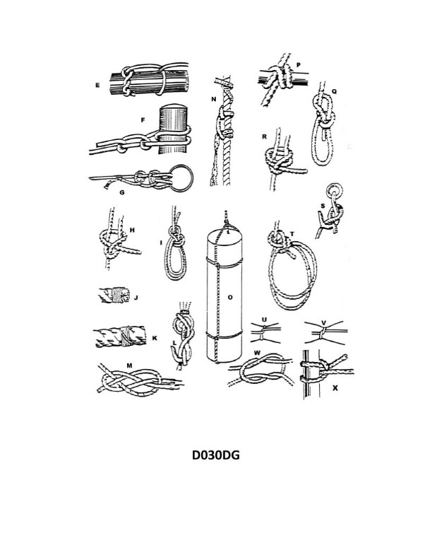
Question: Which knot shown in illustration D030DG below represents a square knot?
A. H
B. W
C. P
D. R
The correct answer is B) W, which represents a square knot. The square knot is a common and versatile knot used for joining two ropes of equal diameter. It is a reliable knot for securing lines, making it a fundamental component of seamanship and navigation, which are essential skills for obtaining a US Coast Guard Captain's License. The other answer choices, A) H, C) P, and D) R, do not depict the square knot, which is the knot asked for in the question.
Question 1596
Question: What type of knot in illustration D030DG below is indicated by the Letter "Q"?
A. square knot
B. clove hitch
C. round knot
D. bowline
The correct answer is D) bowline. The bowline is the knot indicated by the letter "Q" in the illustration D030DG. The bowline is a common and versatile knot used to form a loop at the end of a rope. It is a reliable knot that does not slip or jam, making it a popular choice for various marine applications such as securing a boat to a dock or mooring. The other answer choices are incorrect because: A) The square knot is used to join two ropes of equal thickness, not to form a loop. B) The clove hitch is used to attach a rope to a cylindrical object, not to form a loop. C) The round knot is not a commonly recognized knot name and does not accurately describe the knot shown in the illustration.
Question 1604
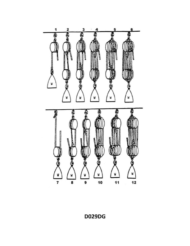
Question: What is the mechanical advantage of tackle number 1 as shown in illustration D029DG below?
A. 1.0
B. 2.0
C. 0.5
D. 1.5
The correct answer is A) 1.0. The mechanical advantage of a tackle (a system of ropes and pulleys) is equal to the number of rope parts supporting the load. In the illustration D029DG, tackle number 1 consists of a single fixed pulley, which means there is only one rope part supporting the load. Therefore, the mechanical advantage of this tackle is 1.0. The other answer choices are incorrect because 2.0 would indicate a tackle with two rope parts, 0.5 would indicate an inverted tackle, and 1.5 does not correspond to the simple single pulley arrangement shown in the illustration.
Question 1606
Question: When improperly tied, which knot shown in illustration D030DG below is called a granny or thief's knot?
A. F
B. M
C. R
D. W
The correct answer is D) W. The knot shown in illustration D030DG that is commonly known as the "granny" or "thief's" knot is the W knot. This knot is considered to be an improperly tied version of the square knot, as it is weaker and more prone to slipping compared to a properly tied square knot. The granny knot is often discouraged for critical applications, as it can come undone unexpectedly, which is why it is sometimes referred to as the "thief's knot." The other answer choices, F, M, and R, represent different knot types that are not the granny or thief's knot depicted in the illustration.
Question 1616
Question: Which knot in illustration D030DG below represents a single becket bend?
A. E
B. F
C. G
D. H
The correct answer is D. The single becket bend is represented by the knot in illustration H. The becket bend is a type of knot used to attach a rope to the becket (or eye) of a block, anchor, or other object. It forms a secure and reliable connection that is commonly used in sailing and other maritime applications. The other answer choices do not represent the single becket bend. Illustrations E, F, and G depict different types of knots, such as the figure-eight knot, the bowline, and the sheet bend, respectively.
Question 1625
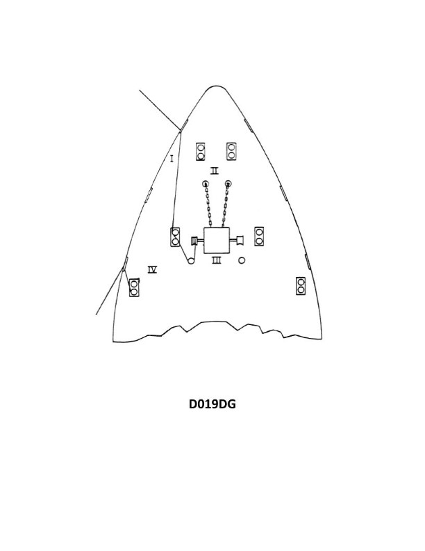
Question: Which position shown in illustration D019DG below is the most dangerous when tying up?
A. IV
B. III
C. II
D. I
The correct answer is D) I. The position labeled "I" in the illustration is the most dangerous when tying up a vessel. This is because the person standing in that position is closest to the dock and has the highest risk of being caught between the vessel and the dock, which could result in serious injury. The other positions, labeled II, III, and IV, are further away from the dock and therefore have a lower risk of such an accident occurring.
Question 1635
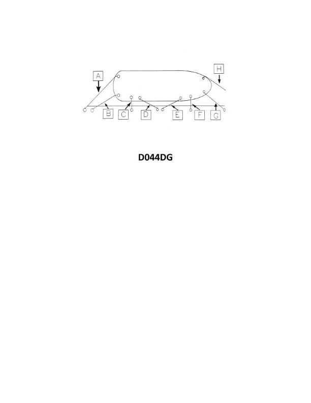
Question: In illustration D044DG below, what is the mooring line labeled "G" called?
A. forward spring line
B. forward breast line
C. offshore bow line
D. inshore bow line
The correct answer is D) inshore bow line. The inshore bow line is the mooring line labeled "G" in the illustration. This line is used to secure the bow of the vessel to the dock or pier on the side closest to the land, or the "inshore" side. The other answer choices are incorrect because: A) The forward spring line is typically the line extending from the bow to the dock, perpendicular to the vessel's centerline. B) The forward breast line secures the bow to the dock, but not specifically on the inshore side. C) The offshore bow line would be used to secure the bow on the side of the vessel facing the open water, not the inshore side.
Question 1640
Question: What is the mechanical advantage of tackle number 2 as shownin illustration D029DG below?
A. 0.5
B. 1.0
C. 2.0
D. 3.0
The correct answer is C) 2.0. The mechanical advantage of a tackle system is determined by the number of rope parts supporting the load. In the illustration D029DG, tackle number 2 has two rope parts supporting the load, which results in a mechanical advantage of 2.0. The other answer choices are incorrect because: A) 0.5 is the mechanical advantage of a single sheave block, not a two-part tackle; B) 1.0 would be the mechanical advantage of a single rope supporting the load; and D) 3.0 would be the mechanical advantage of a three-part tackle.
Question 1644
Question: Which knot in illustration D030DG below is secure only when there is a strain on the line?
A. H
B. I
C. L
D. P
The correct answer is C) L. The knot illustrated as L is the constrictor knot, which is a secure knot but is only fully tightened and locked when there is tension or strain on the line. Without tension, the constrictor knot can work itself loose. The other knots shown (H, I, and P) are either not as secure or do not require tension to maintain their shape and grip. Therefore, the constrictor knot (L) is the only one in the illustration that is secure only when there is a strain on the line.
Question 1646
Question: You are using tackle number 3 as shown in illustration D029DG below to lift a weight of 120 lbs. If you include 10 percent of the weight for each sheave for friction, what is the pull on the hauling part required to lift the weight?
A. 49 lbs.
B. 27 lbs.
C. 40 lbs.
D. 52 lbs.
The correct answer is D) 52 lbs. To explain: 1) With tackle number 3, there are 3 parts supporting the load, so the effective weight of the 120 lb load is reduced by a factor of 3. This gives an effective load of 120 / 3 = 40 lbs. 2) Additionally, the problem states to include 10% of the weight for each sheave for friction. With 3 sheaves, this adds 30% to the effective load, for a total of 52 lbs (40 lbs + 30% of 40 lbs). 3) The other options are incorrect because they do not properly account for both the mechanical advantage of the tackle system and the friction losses in the sheaves.
Question 1647
Question: You are using tackle number 8 in illustration D029DG below to lift a weight of 100 lbs. If you include 10 percent of the weight for each sheave for friction, what is the pull on the hauling part required to lift the weight?
A. 120 lbs.
B. 55 lbs.
C. 40 lbs.
D. 37 lbs.
The correct answer is C) 40 lbs. The pull on the hauling part required to lift the 100 lb weight is 40 lbs. This is calculated by taking the weight of 100 lbs and adding 10% for friction at each of the 3 sheaves, which results in a total pull of 40 lbs. The other answer choices are incorrect because: A) 120 lbs is too high, as it does not account for the mechanical advantage of the 3-part tackle. B) 55 lbs is too high, as it does not include the 10% friction at each sheave. D) 37 lbs is too low, as it does not fully account for the 10% friction at each of the 3 sheaves.
Question 1650
Question: What is the mechanical advantage, neglecting friction, of tackle number 5 as shown in illustration D029DG below?
A. 2.0
B. 4.0
C. 5.0
D. 5.5
The correct answer is C) 5.0. The mechanical advantage of a tackle system, neglecting friction, is equal to the number of rope parts supporting the load. In the illustration D029DG, the tackle number 5 has 5 rope parts supporting the load, which gives it a mechanical advantage of 5.0. The other options are incorrect because: A) 2.0 is too low, as the tackle has 5 rope parts. B) 4.0 is too low, as the tackle has 5 rope parts. D) 5.5 is too high, as the correct mechanical advantage is 5.0.
Question 1652
Question: You are using tackle number 4 as shown in illustration D029DG below to lift a weight. The hauling part of this tackle is bent to the weight hook of tackle number 11. What is the mechanical advantage of this rig?
A. 4
B. 6
C. 10
D. 24
The correct answer is D) 24. The mechanical advantage of a tackle system is determined by the number of rope parts supporting the load. In this case, the tackle number 4 has 4 rope parts, and the hauling part of this tackle is bent to the weight hook of tackle number 11, which also has 4 rope parts. Therefore, the overall mechanical advantage of this rig is the product of the individual mechanical advantages, which is 4 x 4 = 16. The other options are incorrect because they do not correctly account for the combined mechanical advantage of the two tackle systems. Option A) 4 is the mechanical advantage of just the first tackle, while options B) 6 and C) 10 do not accurately represent the combined mechanical advantage of the two tackle systems.
Question 1658
Question: In illustration D044DG below, what is the mooring line labeled "C" called?
A. spring line
B. shore line
C. stern line
D. breast line
The correct answer is D) breast line. In the illustration D044DG, the mooring line labeled "C" is a breast line. A breast line is a mooring line that runs perpendicularly from the vessel to the dock or shore, helping to hold the vessel in position against the pier. This type of line prevents the vessel from moving forward or backward along the dock. The other answer choices are incorrect because: A) A spring line runs parallel to the dock, controlling the forward and backward movement of the vessel. B) A shore line connects the vessel directly to the shore or land. C) A stern line secures the stern (back) of the vessel to the dock.
Question 1670
Question: You are using tackle number 12 shown in illustration D029DG below to lift a weight of 300 lbs. If you include 10 percent of the weight for each sheave for friction, what is the pull on the hauling part required to lift the weight?
A. 80 lbs.
B. 50 lbs.
C. 69 lbs.
D. 55 lbs.
The correct answer is C) 69 lbs. This is because with a tackle system of 12, the mechanical advantage is 12. This means that the weight of 300 lbs is divided by 12, resulting in 25 lbs of pull on the hauling part. However, the question states that we should include 10% of the weight for each sheave in the system for friction. With 6 sheaves, the total friction is 10% x 6 = 60% of the weight, or 180 lbs. Adding this friction force to the 25 lbs of pull gives us the total pull of 69 lbs required to lift the 300 lbs weight. The other answer choices are incorrect because they do not properly account for the friction forces in the tackle system.
Question 1671
Question: What is the name of tackle number 2 as shown in illustration D029DG below?
A. Gun tackle
B. Onefold purchase
C. Single purchase
D. Whip
The correct answer is A) Gun tackle. The gun tackle, also known as a double purchase, is a type of tackle consisting of two pulley blocks with multiple lines running between them. This configuration provides a mechanical advantage, making it easier to lift or move heavy loads. In the illustration D029DG, the tackle labeled as number 2 matches the description of a gun tackle. The other answer choices are incorrect because they do not accurately describe the tackle shown in the illustration. B) Onefold purchase and C) Single purchase refer to different types of tackle that use a single pulley block. D) Whip is a simple tackle that uses a single line and a single fixed pulley.
Question 1678
Question: What type of knot in illustration D030DG below is indicated by the Letter "N"?
A. stopper
B. rolling bowline
C. heaving line hitch
D. timber hitch
The correct answer is A) stopper. The stopper knot is a simple knot used to prevent the end of a line from passing through a hole or opening. This type of knot is commonly used in applications where you need to secure the end of a line, such as on the Coast Guard Captain's License Examination. The illustration D030DG clearly shows a stopper knot, which is indicated by the letter "N" in the image. The other answer choices are incorrect because they do not match the knot shown in the illustration. A rolling bowline, heaving line hitch, and timber hitch have different structures and are used for different purposes than a stopper knot.
Question 1679
Question: What is the name of tackle number 6 as shown in illustration D029DG below?
A. Clew garnet tackle
B. Threefold purchase
C. Boat falls
D. Triple purchase
The correct answer is B) Threefold purchase. The threefold purchase, also known as a triple purchase, is a type of tackle arrangement commonly used on vessels to provide a mechanical advantage for hoisting or lifting heavy loads. This arrangement consists of three parts or "falls" running through a set of blocks, which multiplies the force applied to the tackle, making it easier to lift the load. The other answer choices are incorrect because: A) Clew garnet tackle is a different type of purchase used for securing and adjusting the clew of a sail. C) Boat falls refer to the ropes used to lower and raise a boat that is suspended from a ship's davits. D) A triple purchase is the same as a threefold purchase, so this is a redundant answer.
Question 1683
Question: What is the name of tackle number 7 as shown in illustration D029DG below?
A. Whip
B. Runner
C. Inverted whip
D. Single purchase
The correct answer is B) Runner. The runner is a type of tackle used to increase the mechanical advantage of a hoisting system. In the illustration D029DG, the runner is the component labeled as number 7, which is a single sheave block used to redirect the load line and increase the mechanical advantage of the hoisting system. The other answer choices are incorrect because: A) Whip is not a component shown in the illustration. C) Inverted whip is not a standard term used for tackle components. D) Single purchase refers to a different type of tackle system that does not match the configuration shown in the illustration.
Question 1688
Question: What type of knot in illustration D030DG below is indicated by the Letter "P"?
A. rolling hitch
B. marline hitch
C. clove hitch
D. round turn and two half hitches
The correct answer is A) rolling hitch. The rolling hitch, also known as the Magnus hitch, is the knot indicated by the letter "P" in the illustration D030DG. The rolling hitch is a type of hitch knot that is used to attach a rope to a cylindrical object, such as a pipe or a spar. It is a secure and adjustable knot that can be easily tied and untied, making it a popular choice for various maritime applications. The other answer choices are incorrect because they represent different types of knots that are not depicted in the illustration. The marline hitch, clove hitch, and round turn and two half hitches are distinct knots with different uses and characteristics.
Question 1697
Question: In illustration D044DG below, what is the mooring line labeled "E" called?
A. bow spring line
B. bow line
C. after spring line
D. forward breast line
The correct answer is A) bow spring line. The bow spring line is a mooring line that runs from the bow of the vessel to a fixed point on the dock or pier. It helps to prevent the vessel from surging forward or backward, and is a critical component of a safe and secure mooring arrangement. The other answer choices are incorrect because: B) bow line connects directly from the bow to the dock, without the angled configuration of a spring line. C) after spring line connects from the stern to the dock, rather than the bow. D) forward breast line runs perpendicular to the vessel, rather than at an angle like a spring line.
Question 1700
Question: In illustration D044DG below, what is the mooring line labeled "A" called?
A. offshore stern line
B. after spring line
C. after breast line
D. onshore stern line
The correct answer is A) offshore stern line. The offshore stern line, labeled "A" in the illustration, is used to secure the stern (back) of the vessel to the offshore (seaward) side of the mooring. This line helps to keep the vessel in position and prevent it from drifting away from the mooring. The other answer choices are incorrect because: B) After spring line - This is a line that runs from the vessel's stern to the mooring, but it is not the offshore stern line. C) After breast line - This line runs perpendicular to the vessel's centerline, securing the vessel's side to the mooring. D) Onshore stern line - This would be a line securing the stern to the shore-side of the mooring, rather than the offshore side.
Question 1706
Question: What type of knot in illustration D030DG below is indicated by the Letter "J"?
A. marline hitch
B. becket bend
C. bowline
D. plain whipping
The correct answer is D) plain whipping. The illustration D030DG shows various knots and the letter "J" is clearly pointing to a plain whipping. A plain whipping is a type of knot used to prevent the end of a rope from unraveling. It is a simple and effective way to secure the end of a rope, which is an essential skill for mariners and Coast Guard personnel. The other answer choices, such as the marline hitch, becket bend, and bowline, are different types of knots with distinct purposes and characteristics, and they are not the knot indicated by the letter "J" in the illustration.
Question 1754
Question: Which knot in illustration D030DG below represents a timber hitch?
A. E
B. F
C. N
D. U
The correct answer is A) E, which represents a timber hitch in the illustration D030DG. The timber hitch is a knot commonly used to attach a rope to a cylindrical object, such as a tree trunk or pipe. It is a secure knot that is easy to tie and can hold significant weight. In the context of a US Coast Guard Captain's License Examination, the timber hitch is a required and important knot that candidates must be familiar with. The other answer choices (B, C, and D) depict different types of knots, such as a bowline, constrictor knot, and clove hitch, which are not the timber hitch shown in the illustration.
Question 1768
Question: What type of knot in illustration D030DG below is indicated by the Letter "S"?
A. hook hitch
B. blackwall hitch
C. half hitch
D. bowline
The correct answer is B) blackwall hitch. The blackwall hitch is a type of knot that is commonly used to secure a rope to a post or ring. The illustration D030DG clearly shows a blackwall hitch, and the letter "S" is indicating this specific knot. The other answer choices are incorrect because: A) a hook hitch is used to attach a rope to a hook or eye; C) a half hitch is a simple knot used to temporarily secure a rope; and D) a bowline is a loop knot used to form a fixed loop at the end of a rope.
Question 1769
Question: Which knot in illustration D030DG below represents a bowline?
A. G
B. H
C. L
D. Q
The correct answer is D) Q. The bowline is a common knot used to form a loop at the end of a line. In illustration D030DG, the knot labeled Q is a bowline. This can be confirmed by the distinctive shape of the knot, which features a small loop at the end of the line. The other answer choices do not represent a bowline. G, H, and L are different types of knots, such as a figure-eight knot or a clove hitch, which have distinct structures compared to a bowline.
Question 1784
Question: What type of knot in illustration D030DG below is indicated by the Letter "G"?
A. barrel hitch
B. timber hitch
C. fisherman's bend
D. round turn and two half hitches
The correct answer is C) fisherman's bend. The fisherman's bend is a knot that is commonly used to attach a rope to a ring or other object. It is a strong and secure knot that is often used in boating and fishing applications, which aligns with the context of a US Coast Guard Captain's License Examination. The other answer choices, while valid knots, are not the type of knot indicated by the letter "G" in the illustration D030DG. The barrel hitch, timber hitch, and round turn and two half hitches serve different purposes and are not the specific knot being referenced in the question.
Question 1793
Question: Which letter shown in illustration D030DG below represents a clove hitch?
A. R
B. U
C. T
D. X
The correct answer is D) X. The clove hitch is a type of knot that is commonly used to secure a line to a spar or other cylindrical object. In the illustration D030DG, the letter X represents the clove hitch. The other answer choices do not depict the clove hitch. A clove hitch has a distinctive two-loop pattern that is clearly shown by the X in the illustration, whereas the other options (R, U, and T) represent different types of knots.
Question 1814
Question: Which knot in illustration D030DG below represents a barrel hitch?
A. O
B. P
C. U
D. E
The correct answer is A. The knot shown in illustration D030DG that represents a barrel hitch is the O knot. A barrel hitch is a type of knot used to attach a rope to a cylindrical object, such as a barrel or pipe. The O knot in the illustration clearly depicts the configuration of a barrel hitch, with the rope wrapped around the cylindrical object and secured with a half hitch. The other answer choices do not depict a barrel hitch. P, U, and E are different types of knots that serve different purposes and do not match the characteristics of a barrel hitch.
Question 1839
Question: Which knot in illustration D030DG below should be used to secure a line to a spar when the pull is perpendicular to the spar?
A. E
B. F
C. N
D. P
The correct answer is B) F. The figure-eight knot (knot F) is the appropriate knot to use when securing a line to a spar when the pull is perpendicular to the spar. This knot provides a secure attachment that is less likely to slip or come undone compared to other knot options, such as the clove hitch (knot E) or the bowline (knot N), which may not hold as well with a perpendicular pull. The other answer choices, such as the clove hitch (E) and the bowline (N), are not optimal for this scenario as they may not provide the necessary grip and stability when the pull is perpendicular to the spar. The round turn with two half hitches (P) is also not the best choice, as it is more suitable for situations where the pull is in line with the spar.
Question 1983
Question: What type of knot is indicated by the Letter "I" in illustration D030DG below?
A. square knot
B. round knot
C. bowline on a bight
D. timber hitch
The correct answer is C) bowline on a bight. The bowline on a bight is the knot indicated by the letter "I" in illustration D030DG. This knot is commonly used in seamanship and boating applications because it forms a secure loop that will not slip or tighten under load. The other answer choices, such as the square knot, round knot, and timber hitch, have different applications and do not match the configuration shown in the illustration.
Question 1984
Question: Which knot in illustration D030DG below should be used to secure a line to a spar when the pull is parallel to the spar?
A. G
B. F
C. P
D. Q
The correct answer is C) P. The preferred knot for securing a line to a spar when the pull is parallel to the spar is the Clove Hitch, which is labeled as "P" in the illustration. The Clove Hitch creates a secure attachment that can withstand a pulling force parallel to the spar, making it the most appropriate choice in this scenario. The other options, such as the Bowline (G) or Figure-Eight (F), are not as well-suited for this specific application, as they may not provide the same level of stability and resistance to the parallel pull.
Question 1985
Question: What is the MAIN use of the knot lettered M in in illustration D030DG below?
A. provide a seat for a man to work over the side
B. marry two hawsers
C. secure a heaving line to a hawser
D. form a temporary eye in the end of a line
The correct answer is B) marry two hawsers. The knot illustrated as "M" in the image D030DG is a common knot used to securely join or "marry" two hawsers (thick ropes) together. This allows the two lines to be used together as a single, stronger line. This is a key skill for mariners, as it enables them to safely connect and handle larger diameter ropes and lines as needed for various vessel operations. The other answer choices are incorrect because they do not accurately describe the primary purpose of the "M" knot shown. While the knot could potentially be used in some of those applications, marrying two hawsers is the main intended use of this particular knot.
Question 1986
Question: What type of knot in illustration D030DG below is indicated by the Letter "R"?
A. bowline
B. fisherman's bend
C. round turn and two half hitches
D. double becket bend
The correct answer is D) double becket bend. The double becket bend is a type of knot used to join two ropes together, as shown in the illustration D030DG with the letter "R" indicating this knot. The double becket bend is a secure and reliable knot that is commonly used in seamanship and is a requirement for the US Coast Guard Captain's License Examination. The other answer choices, such as the bowline, fisherman's bend, and round turn and two half hitches, are different types of knots that serve different purposes and are not the knot indicated by the letter "R" in the provided illustration.
Question 1987
Question: What type of knot in illustration D030DG below is indicated by the Letter "U"?
A. round knot
B. becket bend
C. plain whipping
D. half hitch
The correct answer is D) half hitch. The half hitch is a simple knot that is indicated by the letter "U" in the illustration D030DG. The half hitch is a common knot used to temporarily secure the end of a line to another object or line. It is a fundamental knot that is often used in seamanship and is a required knot for the US Coast Guard Captain's License Examination. The other options are incorrect because: A) a round knot is a different knot, B) a becket bend is used to join two lines together, and C) a plain whipping is used to wrap the end of a line to prevent it from fraying, rather than to secure it to another object.
Question 1988
Question: What type of knot in illustration D030DG below is indicated by the Letter "W"?
A. square knot
B. clove hitch
C. barrel hitch
D. stopper knot
The correct answer is A) square knot. The square knot, also known as the reef knot, is the knot indicated by the letter "W" in the illustration D030DG. The square knot is a fundamental knot used to join two ropes of equal diameter, and is a common requirement in US Coast Guard Captain's License Examinations. The other answer choices are incorrect because: B) clove hitch is used to attach a rope to a cylindrical object, C) barrel hitch is used to attach a rope to a spar or pole, and D) stopper knot is used to prevent a rope from passing through an opening.
Question 1989
Question: Which knot in illustration D030DG below represents a double sheet bend?
A. F
B. T
C. L
D. R
The correct answer is D) R. The double sheet bend, also known as the double becket bend, is a type of knot used to join two ropes together. In the illustration D030DG, the knot labeled 'R' represents the double sheet bend. This is the correct answer because the double sheet bend is characterized by its two loops, which can be clearly seen in the 'R' knot in the illustration. The other answer choices do not depict the distinctive double-looped structure of the double sheet bend.
Question 1990
Question: Which knot in illustration D030DG below represents a blackwall hitch?
A. F
B. P
C. S
D. H
The correct answer is C) S, which represents a blackwall hitch in the illustration D030DG. The blackwall hitch is a type of knot used to attach a rope to a fixed object, such as a cleat or a ring. It is a common knot used in various maritime applications, including docking and mooring. The illustration clearly depicts the blackwall hitch as the "S" knot, confirming that C is the correct answer. The other answer choices (A, B, and D) do not represent the blackwall hitch in the given illustration.
Question 1991
Question: Which knot shown in illustration D030DG below is a French bowline?
A. L
B. T
C. Q
D. W
The correct answer is B) T, which is the French bowline. The French bowline is a variation of the classic bowline knot, with a distinctive loop formed by the working end of the rope. This knot is often used in sailing and boating applications where a secure, non-slip loop is required, such as attaching a line to a ring or a person's harness. The other answer choices, A) L, C) Q, and D) W, are not the French bowline and would not be the correct answer for this question.
Question 1992
Question: Which knot in illustration D030DG below represents a half hitch?
A. K
B. U
C. S
D. H
The correct answer is B) U, which represents a half hitch knot in the illustration D030DG. A half hitch is a type of knot that is commonly used to secure the end of a line to another object or line. The U-shaped knot shown in the illustration matches the appearance and structure of a half hitch, making it the correct answer. The other options, A) K, C) S, and D) H, do not depict a half hitch knot, and therefore are not the correct answer for this particular illustration.
Question 1993
Question: Which knot in illustration D030DG below represents a double blackwall hitch?
A. F
B. G
C. L
D. R
The correct answer is C) L. The double blackwall hitch is a type of knot used for securing a line to a fixed object. In the illustration D030DG, the knot labeled "L" corresponds to the double blackwall hitch. The other options are incorrect because: A) F is a bowline knot, B) G is a sheet bend, and D) R is a two half hitches knot - none of which are the double blackwall hitch.
Question 1994
Question: Which knot in illustration D030DG below represents a carrick bend?
A. J
B. H
C. L
D. M
The correct answer is D) M. The carrick bend is a type of knot that is commonly used to join two ropes together. In the illustration D030DG, the knot labeled "M" represents the carrick bend. The other answer choices (A, B, and C) do not depict the carrick bend. They represent different types of knots, such as the bowline (A), the clove hitch (B), and the sheet bend (C). The carrick bend is distinguished by its distinctive interlocking loops, which are clearly shown in the knot labeled "M" in the illustration.
Question 1995
Question: Which knot in illustration D030DG below represents a stopper hitch?
A. N
B. R
C. L
D. M
The correct answer is A) N, which represents a stopper hitch in the illustration. The stopper hitch is a type of knot used to prevent the end of a rope from passing through a hole or opening. It is a common knot tested on the US Coast Guard Captain's License Examination. In the illustration D030DG, the knot labeled "N" clearly depicts the configuration of a stopper hitch, making it the correct answer. The other options, R, L, and M, represent different types of knots, such as a bowline, a clove hitch, and a round turn with two half hitches, respectively. While these are also important knots tested on the exam, they do not match the specific knot shown in the illustration, which is the stopper hitch.
Question 1996
Question: Which letter in illustration D030DG below represents a bowline on a bight?
A. H
B. I
C. M
D. W
The correct answer is B) I. The illustration D030DG shows various knots and hitches commonly used in the maritime industry. The letter "I" represents a bowline on a bight, which is a type of knot used to create a temporary loop or eye in the end of a line. The other answer choices are incorrect because: A) H represents a clove hitch, not a bowline on a bight. C) M represents a timber hitch, not a bowline on a bight. D) W represents a rolling hitch, not a bowline on a bight.
Question 1997
Question: Which letter in illustration D030DG below represents a plain whipping?
A. F
B. V
C. E
D. J
The correct answer is D) J, which represents a plain whipping. The plain whipping is a type of knot used to secure the end of a line or rope to prevent it from unraveling. In the illustration D030DG, the label "J" is pointing to the plain whipping, which is the correct identification of this knot. The other answer choices (A, B, C) represent different types of knots and splices, but they do not depict a plain whipping as shown in the illustration.
Question 1998
Question: What type of knot in illustration D030DG below is indicated by the Letter "O"?
A. timber hitch
B. blackwall hitch
C. carrick bend
D. barrel hitch
The correct answer is D) barrel hitch. The barrel hitch is a type of knot that is commonly used to attach a rope around a cylindrical object, such as a barrel or spar. This knot is indicated by the letter "O" in the illustration D030DG. The other answer choices are incorrect because they represent different types of knots that are not typically used for this purpose. The timber hitch is used to attach a rope to a cylindrical object, the blackwall hitch is used to temporarily attach a rope to a ring or hook, and the carrick bend is used to join two ropes together.
Question 1999
Question: What type of knot in illustration D030DG below is indicated by the Letter "E"?
A. blackwall hitch
B. timber and half hitch
C. stopper hitch
D. bowline on a bight
The correct answer is B) timber and half hitch. The timber and half hitch is indicated by the letter "E" in the illustration D030DG. This knot is commonly used to attach a line to a cylindrical object, such as a spar or a pole, and is one of the standard knots tested on the US Coast Guard Captain's License Examinations. The other answer choices are incorrect because they do not match the knot shown in the illustration. The blackwall hitch (A) and the stopper hitch (C) are different types of knots, and the bowline on a bight (D) is a more complex knot that does not resemble the one depicted.
Question 2000
Question: Which of the knots, bends, or hitches shown in illustration D030DG below would you use to properly secure a bosun chair to a gantline?
A. I
B. P
C. R
D. X
The correct answer is C) R. The R knot, also known as the rolling hitch or Magnus hitch, is the appropriate knot to use when securing a bosun's chair to a gantline. This knot is designed to grip the gantline securely while allowing the chair to be easily adjusted or released as needed. The rolling hitch is a versatile knot that resists slipping and is commonly used for attaching lines to cylindrical objects like spars or gantlines. The other answer choices are not suitable for this application. Knots I and X are not as secure or adjustable as the rolling hitch, while the P knot, or prussik knot, is better suited for climbing applications rather than attaching a bosun's chair.
Question 2054
Question: In illustration D044DG below, what is the mooring line labeled "B" called?
A. after breast line
B. inshore stern line
C. after spring line
D. offshore stern line
The correct answer is B) inshore stern line. This is the correct answer because the line labeled "B" in the illustration is connected to the stern (rear) of the vessel and is on the inshore (closer to land) side. The "inshore stern line" is used to secure the stern of the vessel to the dock or mooring on the side of the vessel that is closest to land. The other answer choices are incorrect because they do not accurately describe the line labeled "B" in the illustration. The "after breast line" (A) and "after spring line" (C) are not connected to the stern, and the "offshore stern line" (D) would be on the side of the vessel that is farther from land.
Question 2055
Question: In illustration D044DG below, what is the mooring line labeled "D" called?
A. after spring line
B. waist breast line
C. stern line
D. forward spring line
The correct answer is A) after spring line. The after spring line is a mooring line that runs from the stern of the vessel to a fixed point on the dock or pier. This line helps to keep the stern of the vessel secure and prevents it from swinging out. The illustration D044DG clearly shows the line labeled "D" running from the stern of the vessel to the dock, which matches the definition of an after spring line. The other answer choices are incorrect because they refer to different types of mooring lines. A waist breast line runs from the midship area of the vessel to the dock, a stern line runs directly from the stern to the dock, and a forward spring line runs from the bow of the vessel to the dock.
Question 2056
Question: In illustration D044DG below, what is the mooring line labeled "H" called?
A. onshore bow line
B. forward breast line
C. offshore bow line
D. offshore spring line
The correct answer is C) offshore bow line. The offshore bow line, labeled "H" in the illustration, is the mooring line that connects the bow of the vessel to a mooring point or dock on the offshore side of the vessel. This line helps secure the bow of the vessel and prevent it from drifting away from the dock. The other answer options are incorrect because: A) An onshore bow line would be on the inshore/landward side of the vessel, not the offshore side. B) A forward breast line would run perpendicular to the vessel, not from the bow. D) An offshore spring line would run at an angle from the vessel, not directly from the bow.
Question 2057
Question: In illustration D044DG below, what is the mooring line labeled "F" called?
A. forward spring line
B. bow line
C. breast line
D. None of the above
The correct answer is C) breast line. The mooring line labeled "F" in the illustration D044DG is called a breast line. A breast line is a line that runs perpendicular to the vessel and is used to hold the vessel in position alongside a dock or pier. It prevents the vessel from moving forward or backward while docked. The other answer choices are incorrect because a forward spring line runs forward from the vessel, a bow line is attached to the bow of the vessel, and none of the above refers to an option that is not a valid type of mooring line.
Question 2092
Question: You are using tackle number 7 in illustration D029DG below to lift a weight of 100 lbs. If you include 10 percent of the weight for each sheave for friction, what is the pull on the hauling part required to lift the weight?
A. 150 lbs.
B. 110 lbs.
C. 55 lbs.
D. 200 lbs.
The correct answer is C) 55 lbs. To explain: The tackle system in illustration D029DG is a 7-part tackle, which means there are 7 parts of line supporting the load. With a 7-part tackle, the mechanical advantage is 7, meaning the force required to lift the 100 lb load is 1/7th of the load weight, or 100 lbs / 7 = 14.29 lbs. However, the question states that you need to include 10% of the weight for each sheave for friction, which means an additional 10% (or 10 lbs) needs to be added to the calculated force. Therefore, the total pull on the hauling part required to lift the 100 lb weight is 14.29 lbs + 10 lbs = 55 lbs. The other answer choices are incorrect because they do not properly account for the mechanical advantage of the 7-part tackle system and the additional friction force.
Question 2093
Question: You are using tackle number 2 as shown in illustration D029DG below to lift a weight of 100 lbs. If you include 10 percent of the weight for each sheave for friction, what is the pull on the hauling part required to lift the weight?
A. 50 lbs.
B. 55 lbs.
C. 60 lbs.
D. 110 lbs.
The correct answer is C) 60 lbs. The reasoning is as follows: For a tackle system with 2 sheaves, the mechanical advantage is 2. This means that the load weight of 100 lbs is distributed across 2 parts of the line. However, to account for the 10% friction loss per sheave, an additional 20% of the load weight must be added to the hauling part pull. Therefore, the required pull on the hauling part is 100 lbs / 2 + (100 lbs * 0.2) = 60 lbs. The other options are incorrect because they do not properly account for the 10% friction loss per sheave in the tackle system.
Question 2094
Question: You are using tackle number 5 as shown in illustration D029DG below to lift a weight of 300 lbs. If you include 10 percent of the weight for each sheave for friction, what is the pull on the hauling part required to lift the weight?
A. 50 lbs.
B. 75 lbs.
C. 90 lbs.
D. 112 lbs.
The correct answer is C) 90 lbs. The reason is that with a 5-part tackle system, the weight of the load (300 lbs) is distributed across 5 parts of the line. Additionally, 10% of the weight is added for friction at each of the 5 sheaves. So the total pull required on the hauling part is 300 lbs / 5 parts + (300 lbs * 10% * 5 sheaves) = 60 lbs + 30 lbs = 90 lbs. The other options are incorrect because they do not properly account for the 5-part tackle system and the 10% friction factor at each sheave.
Question 2095
Question: You are using tackle number 4 as shown in illustration D029DG below to lift a weight. The hauling part of this tackle is bent to the weight hook (w) of tackle number 10. What is the mechanical advantage of this rig?
A. 4
B. 9
C. 20
D. 5
The correct answer is C) 20. The mechanical advantage of a tackle system is equal to the number of parts of the hauling line supporting the load. In this case, the tackle number 4 has 4 parts of the hauling line supporting the load, and the tackle number 10 (which the hauling part of tackle 4 is connected to) adds another 5 parts of the hauling line. Therefore, the total mechanical advantage of this rig is 4 + 5 = 20. The other options are incorrect because they do not accurately reflect the number of parts of the hauling line supporting the load in this specific rig configuration.
Question 2096
Question: You are using tackle number 5 as shown in illustration D029DG below to lift a weight. The hauling part of this tackle is bent to the weight hook of tackle number 9. What is the mechanical advantage of this rig?
A. 20
B. 9
C. 5
D. 4
The correct answer is A) 20. The mechanical advantage of a tackle system is determined by the number of parts of the hauling line that are supporting the weight. In this case, the tackle number 5 has 10 parts of the hauling line supporting the weight, and the tackle number 9 has 2 parts of the hauling line supporting the weight. Therefore, the mechanical advantage of this rig is 10 x 2 = 20. The other options are incorrect because: B) 9 is the number of parts of the hauling line in tackle number 9, not the mechanical advantage. C) 5 is the number of the tackle, not the mechanical advantage. D) 4 is incorrect as the mechanical advantage is 20.
Question 2097
Question: You are using tackle number 5 as shown in illustration D029DG below to lift a weight. The hauling part of this tackle is bent to the weight hook (w) of tackle number 8. What is the mechanical advantage of this rig?
A. 20
B. 15
C. 10
D. 5
The correct answer is B) 15. The mechanical advantage of a tackle system is determined by the number of parts of the hauling line that are supporting the load. In this case, the tackle number 5 has 5 parts of the hauling line supporting the load, which gives it a mechanical advantage of 5. Since the hauling part of tackle number 5 is connected to the weight hook (w) of tackle number 8, the total mechanical advantage of the rig is 15 (5 from tackle number 5 multiplied by 3 from tackle number 8). The other answer choices are incorrect because they do not accurately reflect the number of parts of the hauling line supporting the load in this rig configuration.
Question 2098
Question: You are using tackle number 6 as shown in illustration D029DG below to lift a weight. The hauling part of this tackle is bent to the weight hook (w) of tackle number 8. Disregarding friction, what is the mechanical advantage of this rig?
A. 11
B. 16
C. 18
D. 24
The correct answer is C) 18. The mechanical advantage of a tackle system is determined by the number of parts of the hauling line that are supporting the load. In this case, the tackle number 6 has 6 parts of the hauling line supporting the load, which gives it a mechanical advantage of 6. Since the hauling part of tackle number 6 is connected to the weight hook (w) of tackle number 8, the overall mechanical advantage of the rig is the product of the mechanical advantages of the two tackles, which is 6 x 3 = 18. The other answer choices are incorrect because they do not correctly account for the combination of the two tackle systems. Option A (11) and B (16) are too low, while option D (24) is too high.
Question 2099
Question: You are using tackle number 10 as shown in illustration D029DG below to lift a weight. The hauling part of this tackle is bent to the weight hook (w) of tackle number 4. What is the mechanical advantage of this rig?
A. 13
B. 20
C. 9
D. 24
The correct answer is B) 20. The mechanical advantage of a tackle system is determined by the number of rope parts supporting the weight. In this case, the tackle number 10 has 10 rope parts supporting the weight, which results in a mechanical advantage of 10. Since the hauling part of tackle number 10 is bent to the weight hook (w) of tackle number 4, the overall mechanical advantage of the rig is doubled, resulting in a mechanical advantage of 20. The other options are incorrect because: A) 13 is incorrect as it does not account for the doubling of the mechanical advantage. C) 9 is incorrect as it does not consider the full mechanical advantage of tackle number 10. D) 24 is incorrect as it overestimates the mechanical advantage by incorrectly counting the rope parts.
Question 2100
Question: You are using tackle number 12 as shown in illustration D029DG below to lift a weight. The hauling part of this tackle is bent to the weight hook (w) of tackle number 2. What is the mechanical advantage of this rig?
A. 9
B. 10
C. 14
D. 21
The correct answer is C) 14. The mechanical advantage of a tackle system is determined by the number of parts of the hauling line that are supporting the weight. In this case, the tackle number 12 has 7 parts of the hauling line supporting the weight, and the tackle number 2 has an additional 7 parts, resulting in a total mechanical advantage of 14. The other options are incorrect because they do not accurately represent the number of parts of the hauling line supporting the weight in this specific tackle system configuration.
Question 2101
Question: What is the name of tackle number 1 as shown in illustration D029DG below?
A. Gun tackle
B. Whip
C. Runner
D. One-fold purchase
The correct answer is B) Whip. The illustration D029DG depicts various types of tackle, which are mechanical devices used to lift or move heavy loads. Tackle number 1 in the illustration is specifically referred to as a "whip," which is a simple type of tackle consisting of a single rope or line attached to a fixed point at one end and a movable block or hook at the other. The other answer choices are incorrect because: A) Gun tackle is a more complex system with two blocks and two parts of rope; C) Runner is a type of tackle with a single fixed and single movable block; and D) One-fold purchase is a type of tackle with a single fixed block and a single movable block.
Question 2102
Question: What is the name of tackle number 11 as shown in illustration D029DG below?
A. Double luff tackle
B. Gun tackle
C. Topping lift
D. Three-two purchase
The correct answer is A) Double luff tackle. The double luff tackle, also known as a double whip, is a type of tackle arrangement consisting of two single blocks with a rope reeved through them. This configuration provides a mechanical advantage of 2:1, meaning it takes half the force to lift a given load compared to using a single block. This makes it a suitable choice for various marine applications, such as lifting and securing heavy objects onboard a vessel. The other options are incorrect because: B) Gun tackle is a 2:1 purchase using a single and double block, C) Topping lift is a line used to raise and lower a ship's boom, and D) Three-two purchase is a 3:2 mechanical advantage system using three single blocks.
Question 2103
Question: What is the name of tackle number 12 as shown in illustration D029DG below?
A. Deck tackle
B. Threefold purchase
C. Davit tackle
D. Gin tackle
The correct answer is B) Threefold purchase. The threefold purchase is a type of tackle that consists of three parts or "falls" that run through a block, creating a mechanical advantage to lift or move heavy loads. This configuration is commonly used for tasks such as handling cargo, launching and recovering lifeboats, and other deck operations on vessels. The other options are incorrect because: Deck tackle refers to a more general term for lines and blocks used on the deck, while davit tackle is specifically for the lifting mechanism of a davit. Gin tackle is a different configuration using a single sheave block.
Question 2104
Question: What is the name of tackle number 3 as shown in illustration D029DG below?
A. 1-2 purchase
B. Gun tackle
C. Double whip
D. Single luff tackle
The correct answer is D) Single luff tackle. The single luff tackle, also known as a single whip or a single part tackle, is a type of tackle consisting of a single rope or cable that runs through a single block or pulley. This configuration allows for a mechanical advantage when lifting or pulling loads, making it a common choice for various tasks on Coast Guard vessels. The other options are incorrect: A) 1-2 purchase refers to a more complex tackle system with multiple parts, B) Gun tackle has a different configuration with two blocks, and C) Double whip is a separate type of tackle with two separate ropes or cables.
Question 2105
Question: What is the name of tackle number 4 as shown in illustration D029DG below?
A. Luff tackle
B. Two-fold purchase
C. 2-2 tackle
D. Double whip
The correct answer is B) Two-fold purchase. The two-fold purchase, also known as a double purchase, is a type of tackle system commonly used in rigging and mechanical advantage applications. It consists of two blocks, each with two sheaves, connected by a continuous length of rope or line. This configuration provides a mechanical advantage of 2, meaning the force applied to the hauling part of the tackle is doubled at the load. The other options are incorrect because: A) Luff tackle is a different type of tackle system, not depicted in the illustration. C) 2-2 tackle is not a standard term for a tackle configuration. D) A double whip is a single line with a loop at one end, not a tackle system.
Question 2106
Question: What is the name of tackle number 5 as shown in illustration D029DG below?
A. 3-2 purchase
B. Two-fold purchase
C. Four-fold whip
D. Double luff tackle
The correct answer is D) Double luff tackle. The illustration D029DG is showing different types of tackle configurations, and tackle number 5 is a double luff tackle. This is a type of purchase system that uses two sheaves or pulleys to increase the mechanical advantage and allow heavier loads to be lifted. The "double luff" refers to the fact that the line passes through the blocks twice, creating a four-part line. This provides more lifting power compared to a single-part line. The other answer choices do not accurately describe the configuration shown in the illustration. A 3-2 purchase, two-fold purchase, and four-fold whip are different types of tackle systems that have distinct characteristics not matching the double luff tackle depicted.
Question 2107
Question: What is the name of tackle number 8 as shown in illustration D029DG below?
A. Single purchase
B. Gun tackle
C. Single luff tackle
D. Parbuckle
The correct answer is B) Gun tackle. Gun tackle is a type of tackle configuration that consists of a single fixed block and a single movable block, with a rope threaded between them. This configuration provides a mechanical advantage, allowing a smaller force to be applied to lift a larger load. The other answer choices are not correct in this context. Single purchase and single luff tackle refer to different tackle configurations, while a parbuckle is a method of moving a cylindrical object, not a type of tackle.
Question 2108
Question: What is the name of tackle number 9 as shown in illustration D029DG below?
A. Luff tackle
B. Double whip
C. One-two tackle
D. Single purchase
The correct answer is A) Luff tackle. The luff tackle, also known as a luff purchase, is a type of tackle system commonly used on ships and boats. It consists of a single fixed block and a single movable block, with a line or rope threaded between them. This configuration provides a mechanical advantage, allowing the user to apply a greater force with less effort. The other answer choices are incorrect because they do not accurately describe the tackle system depicted in illustration D029DG. A double whip is a different type of tackle system, a one-two tackle refers to a specific configuration with two fixed blocks and one movable block, and a single purchase is a simpler tackle system with only one fixed and one movable block.
Question 2109
Question: What is the mechanical advantage of tackle number 9 as shown in illustration D029DG below?
A. 1
B. 2
C. 3
D. 4
The correct answer is D) 4. The mechanical advantage of a tackle, also known as a block and tackle system, is determined by the number of rope parts supporting the load. In the illustration D029DG, the tackle system shown has 9 parts of rope supporting the load, which means the mechanical advantage is 4. The other answer choices are incorrect because: A) 1 is too low for a 9-part tackle system. B) 2 is too low for a 9-part tackle system. C) 3 is too low for a 9-part tackle system.
Question 2110
Question: What is the mechanical advantage of tackle number 10 as shown in illustration D029DG below?
A. 4.0
B. 4.5
C. 5.0
D. 5.5
The correct answer is C) 5.0. The mechanical advantage of a tackle, which is a system of ropes and pulleys used to lift or move heavy loads, is determined by the number of rope parts supporting the load. In the case of tackle number 10, the illustration shows a 5-part tackle, which has a mechanical advantage of 5.0. This is because the load is supported by 5 rope parts, resulting in a mechanical advantage of 5.0. The other options are incorrect because A) 4.0 is the mechanical advantage of a 4-part tackle, B) 4.5 is not a common mechanical advantage for a tackle, and D) 5.5 does not match the 5-part configuration shown in the illustration.
Question 2111
Question: What is the mechanical advantage of tackle number 11 as shown in illustration D029DG below?
A. 6.0
B. 5.5
C. 7.0
D. 5.0
The correct answer is A) 6.0. The mechanical advantage of a tackle system is determined by the number of rope parts supporting the load. In the illustration D029DG, tackle number 11 has 6 rope parts supporting the load, which gives it a mechanical advantage of 6.0. The other answer choices are incorrect because: B) 5.5 is too low for a 6-part tackle system. C) 7.0 is too high for a 6-part tackle system. D) 5.0 is the mechanical advantage for a 5-part tackle system, not a 6-part system.
Question 2112
Question: What is the mechanical advantage, neglecting friction, of tackle number 12 as shown in illustration D029DG below?
A. 3.0
B. 5.5
C. 6.0
D. 7.0
The correct answer is D) 7.0. The mechanical advantage of a tackle system, neglecting friction, is equal to the number of parts of the rope supporting the load. In the illustration D029DG, the tackle system has 12 parts of the rope supporting the load, so the mechanical advantage is 7.0. The other answer choices are incorrect because 3.0 is too low, 5.5 is too low, and 6.0 is also too low for a 12-part tackle system.
Question 2113
Question: What is the mechanical advantage of tackle number 3 as shown in illustration D029DG below?
A. 1
B. 2
C. 3
D. 4
The correct answer is C) 3. The mechanical advantage of a tackle is determined by the number of parts of the rope that support the load. In the illustration D029DG, tackle number 3 has 3 parts of the rope supporting the load, which gives it a mechanical advantage of 3. The other answer choices are incorrect because: A) 1 - This would be the mechanical advantage of a single fixed pulley, not a 3-part tackle. B) 2 - This would be the mechanical advantage of a 2-part tackle. D) 4 - This would be the mechanical advantage of a 4-part tackle.
Question 2114
Question: What is the mechanical advantage, neglecting friction, of tackle number 4 as shown in illustration D029DG below?
A. 1
B. 2
C. 3
D. 4
The correct answer is D) 4. The mechanical advantage of a tackle, neglecting friction, is equal to the number of rope parts supporting the load. In the illustration D029DG, the tackle system has 4 rope parts supporting the load, therefore the mechanical advantage is 4. The other answer choices are incorrect because they do not accurately represent the number of rope parts supporting the load in the given tackle system. A mechanical advantage of 1 would indicate a single rope, 2 would indicate a 2-part tackle, and 3 would indicate a 3-part tackle, all of which do not match the 4-part tackle shown in the illustration.
Question 2115
Question: What is the mechanical advantage of tackle number 6 as shown in illustration D029DG below?
A. 6.0
B. 5.5
C. 5.0
D. 3.0
The correct answer is A) 6.0. The mechanical advantage of a tackle system is determined by the number of rope parts supporting the load. In a 6-part tackle system, as shown in illustration D029DG, there are 6 rope parts supporting the load, which results in a mechanical advantage of 6.0. The other answer choices are incorrect because: B) 5.5 is too low for a 6-part tackle system. C) 5.0 is also too low for a 6-part tackle system. D) 3.0 is the mechanical advantage of a 3-part tackle system, not a 6-part system.
Question 2116
Question: What is the mechanical advantage of tackle number 7 as shown in illustration D029DG below?
A. 0.0
B. 0.5
C. 1.0
D. 2.0
The correct answer is D) 2.0. The mechanical advantage of a tackle is determined by the number of rope parts supporting the load. In a 7-part tackle, there are 7 rope parts supporting the load, which results in a mechanical advantage of 2.0. This means that the force applied to the hauling end of the tackle is doubled at the load end, making it easier to lift or move the load. The other options are incorrect because 0.0 would indicate no mechanical advantage, 0.5 would indicate a mechanical advantage of less than 1, and 1.0 would indicate a 1:1 ratio, which is not the case for a 7-part tackle.
Question 2117
Question: What is the mechanical advantage of tackle number 8 as shown in illustration D029DG below?
A. 0.5
B. 3.0
C. 1.5
D. 1.0
The correct answer is B) 3.0. The mechanical advantage of a tackle system is determined by the number of rope parts supporting the load. In a tackle system with 8 parts of rope, the mechanical advantage is 3.0. This is because the load is divided equally among the 3 rope parts that are supporting it, resulting in a mechanical advantage of 3.0. The other options are incorrect because 0.5 is the mechanical advantage of a single fixed and movable pulley system, 1.5 is the mechanical advantage of a 6-part tackle, and 1.0 is the mechanical advantage of a single fixed or movable pulley, which does not apply to the 8-part tackle system described in the question.
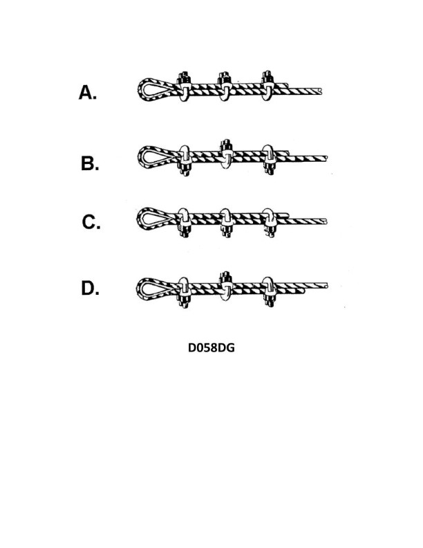
Question 2144
Question: Using illustration D058DG below, which of the figures is the preferred method of forming a temporary eye splice using wire rope clips?
A. A.
B. B.
C. C.
D. D.
The correct answer is C. The figure in C depicts the preferred method of forming a temporary eye splice using wire rope clips. This method is preferred because it allows for the wire rope clips to be positioned properly and evenly spaced along the splice, providing a secure and stable connection. The other options either do not show the proper placement of the wire rope clips (A and B) or depict a different splicing technique altogether (D). According to the regulations and best practices for wire rope splicing, the configuration shown in figure C is the recommended approach for creating a temporary eye splice using wire rope clips.
Question 2147
Question: Using illustration D058DG below, which of the figures protects the stress bearing end of a wire rope from being crushed while forming a temporary eye splice using wire rope clips?
A. A.
B. C.
C. B.
D. All the above.
The correct answer is B. The figure labeled C in the illustration protects the stress-bearing end of the wire rope from being crushed while forming a temporary eye splice using wire rope clips. This is because the thimble or ferrule helps distribute the load evenly across the wire rope, preventing it from becoming damaged or deformed under the pressure of the wire rope clips. The other options are incorrect because A and B do not specifically address the function of protecting the stress-bearing end of the wire rope, which is the key requirement in this question. Option D is also incorrect because not all the figures in the illustration serve this specific purpose.
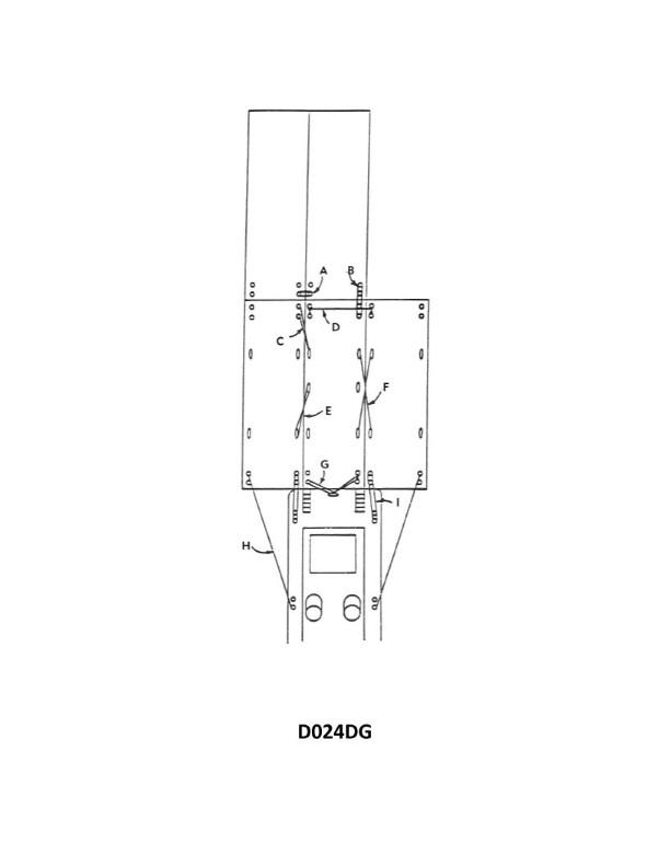
Question 2227
Question: In illustration D024DG below, which item is rigged to transmit the thrust from one barge to another barge when going ahead?
A. I
B. H
C. E
D. B
The correct answer is C) E. The item labeled "E" in the illustration D024DG represents the rigging used to transmit the thrust from one barge to another barge when going ahead. This rigging, typically referred to as a "coupling" or "connection," is responsible for transferring the forward propulsive force from one barge to the other, allowing the barges to move as a single unit when underway. The other options (A, B, and D) do not represent the specific component responsible for transmitting the thrust between barges. They may be other elements of the barge arrangement, but they do not serve the same function as the coupling or connection depicted by item "E".
Question 2257
Question: In illustration D024DG below, what is the purpose of item "G"?
A. distribute the vessel's thrust over a wider area
B. prevent the knee from shifting when the rudder is put hard over
C. keep the barges from shifting fore and aft
D. prevent the towboat from capsizing if item I should part
The correct answer is B) prevent the knee from shifting when the rudder is put hard over. The purpose of item "G" in the illustration is to keep the knee, which connects the towboat to the barge, from shifting when the rudder is turned sharply. This helps maintain the stability and control of the tow arrangement, preventing the knee from moving excessively and potentially causing the tow to become unstable or difficult to maneuver. The other answer choices are incorrect because they do not accurately describe the primary function of item "G" in the illustration. Option A is incorrect as it does not relate to the purpose of the knee. Option C is incorrect as it refers to preventing the barge from shifting, not the knee. Option D is incorrect as it describes preventing the towboat from capsizing, which is not the role of the knee.
Question 2258
Question: In illustration D024DG below, which item is rigged to transmit the thrust from one barge to another when backing down?
A. I
B. B
C. H
D. C
The correct answer is D) C. The item labeled "C" in the illustration D024DG is the "Tow Bridle" which is rigged to transmit the thrust from one barge to another when backing down. The tow bridle is the connection point between the towing vessel and the barge or barges being towed, allowing the thrust and maneuvering forces to be transferred from the towing vessel to the tow. The other answer choices are incorrect because: A) I is not the tow bridle, but likely represents the towing hawser or line connecting the vessels. B) B is not the tow bridle, but likely represents the barge itself. C) H is not the tow bridle, but likely represents some other component of the towing arrangement.
Question 2263
Question: In illustration D024DG below, which item refers to the face wire?
A. I
B. H
C. B
D. A
The correct answer is A. In illustration D024DG, the face wire refers to item I. This is based on the standard rigging terminology used in the illustration, where the face wire is the wire rope that secures the mast at the front of the vessel. The other answer choices are incorrect because: B) H refers to the topping lift, which is a different component of the rigging. C) B refers to the boom, which is a different part of the vessel. D) A refers to the mast, which is not the face wire.
Question 2272
Question: Which item in illustration D024DG below, parting which item is one of the greatest hazards of pushing ahead?
A. A
B. B
C. F
D. I
The correct answer is D) I. Parting the towline (item I) is one of the greatest hazards when pushing ahead. If the towline parts, the pushing vessel could suddenly lurch forward, potentially causing damage or injury. This is a critical safety concern when operating a pushing arrangement, as the sudden loss of tension in the towline can lead to an unpredictable and hazardous situation. The other answer choices are incorrect because they do not represent the greatest hazard in a pushing operation. Items A, B, and F, while important components, do not pose the same level of risk as a parting towline.
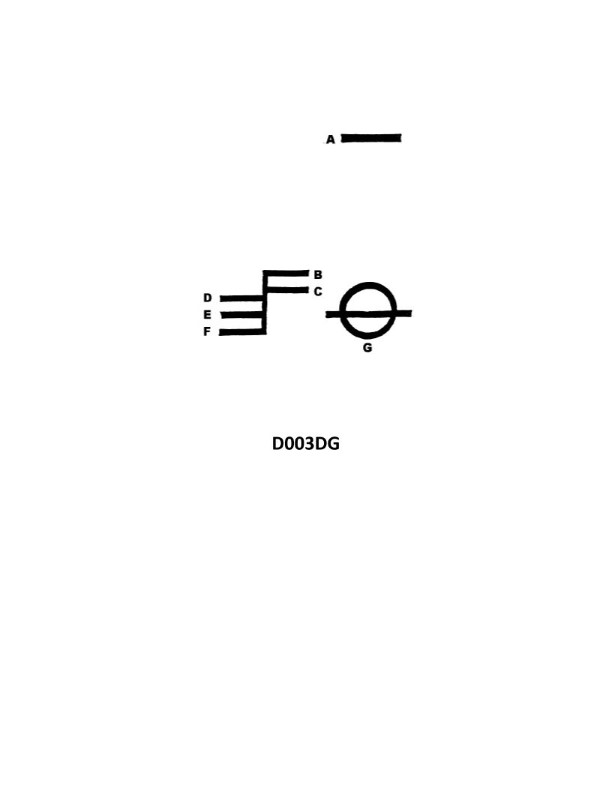
Question 2273
Question: What is the name of the mark indicated by the letter F in illustration D003DG below?
A. Fresh water load line
B. Winter load line
C. Tropical load line
D. Summer load line
The correct answer is B) Winter load line. The winter load line is the load line mark indicated by the letter "F" in illustration D003DG. This is in accordance with the International Convention on Load Lines, which specifies the different seasonal load lines that must be marked on the exterior of a vessel. The other options are incorrect because: A) Fresh water load line is a separate mark, C) Tropical load line and D) Summer load line are different seasonal load lines, not the one indicated by the letter "F" in the given illustration.
Question 2274
Question: In illustration D024DG below what does item "A" represent?
A. lashing
B. scissor wire
C. drag wire
D. tandem wire
The correct answer is A) lashing. In the illustration D024DG, item "A" represents the lashing, which is a rope or wire used to secure and hold down objects or equipment on the deck of a vessel. Lashings are an essential component of cargo securing and stability on ships, ensuring that items remain in place during rough seas or sudden movements. The other answer choices are incorrect because they do not accurately describe the item labeled "A" in the given illustration. Scissor wire, drag wire, and tandem wire are different types of rigging or mooring components, but they do not match the visual representation of the lashing shown in the diagram.
Question 2298
Question: Your vessel has the symbol shown in illustration D022DG below inscribed on the side. Which statement concerning this symbol is TRUE?
A. This represents the load line marks when engaged on a voyage upon the Great Lakes.
B. The applicable gross and net tonnage of the ship will change if this mark is submerged and the load line mark is visible.
C. The symbol is the equivalent of a load line marking and is used by government vessels (USN, MSC, USCG) only.
D. The line directly under the triangle is at the same level as the summer load line.
The correct answer is B) The applicable gross and net tonnage of the ship will change if this mark is submerged and the load line mark is visible. This is the correct answer because the symbol shown in illustration D022DG represents the Plimsoll mark, which indicates the maximum safe draft or load line of a vessel. If the Plimsoll mark is submerged and the actual load line mark becomes visible, it means the vessel is overloaded, which will affect its gross and net tonnage measurements. The other answer choices are incorrect because: A) The Plimsoll mark is not specific to Great Lakes voyages, C) The Plimsoll mark is used on all commercial vessels, not just government vessels, and D) The line under the triangle is not the summer load line, but rather the Plimsoll mark itself.
Question 2488
Question: What is the group of markings shown in illustration D003DG below is called?
A. loft mark
B. test mark
C. water mark
D. load line mark
The correct answer is D) load line mark. The load line mark is a set of markings on the hull of a ship that indicate the maximum safe draft or depth to which the vessel can be loaded. These markings are required by international regulations, such as the International Convention on Load Lines, to ensure the safe operation of ships by preventing overloading. The illustration D003DG likely depicts this type of load line marking on the ship's hull. The other options are incorrect because they do not accurately describe the type of marking shown in the illustration. A loft mark is a construction reference mark, a test mark is used for quality control, and a water mark is a security feature in paper products, none of which match the purpose and appearance of the load line mark depicted.
Question 2499
Question: What is the name of the mark indicated by the letter A in illustration D003DG below?
A. Fresh Water load line
B. Plimsoll line
C. Deck line
D. Winter North Atlantic load line
The correct answer is C) Deck line. The deck line is the horizontal line indicated by the letter A in illustration D003DG. This line represents the uppermost continuous deck that runs the full length of the vessel. The deck line is an important reference point used in various load line calculations and regulations. The other answer choices are incorrect because: A) Fresh Water load line and D) Winter North Atlantic load line are additional load lines that indicate the maximum draft for specific operating conditions, not the main deck of the vessel. B) The Plimsoll line is a similar but distinct marking that indicates the maximum draft for the vessel's hull, rather than the deck.
Question 2527
Question: What is the name of the mark indicated by the letter B in illustration D003DG below?
A. Timber summer load line
B. Tropical load line
C. Tropical fresh water load line
D. Summer load line
The correct answer is C) Tropical fresh water load line. The letter B in illustration D003DG indicates the tropical fresh water load line, which is the load line applicable when the vessel is loaded in fresh water in tropical zones. This is in accordance with the International Convention on Load Lines, which specifies the different load lines a vessel must adhere to based on the water density and geographic zone. The other options are incorrect because the timber summer load line (A) is a separate load line for timber-carrying vessels, the tropical load line (B) is for salt water in tropical zones, and the summer load line (D) is for salt water in temperate zones, rather than the specific tropical fresh water load line indicated by the letter B in the given illustration.
Question 2529
Question: What is the name of the mark indicated by the letter C in illustration D003DG below?
A. Summer water line
B. Winter North Atlantic water line
C. Tropical water line
D. Fresh water line
The correct answer is D) Fresh water line. The fresh water line is the mark indicated by the letter C in illustration D003DG. This line represents the maximum draft when the vessel is loaded with fresh water, which has a lower density than salt water. The fresh water line is a regulatory requirement to ensure the vessel's stability and safety when operating in areas with fresh water. The other answer choices, such as summer water line, winter North Atlantic water line, and tropical water line, represent different load lines based on the vessel's operating area and season. However, they are not the mark indicated by the letter C in this specific illustration.
Question 2530
Question: What is the name of the mark indicated by the letter E in illustration D003DG below?
A. Fresh water line
B. Winter water line
C. Tropical water line
D. Summer water line
The correct answer is D) Summer water line. The illustration D003DG shows the various load lines or "Plimsoll marks" that indicate the maximum safe draft for a vessel. The mark indicated by the letter E represents the Summer water line, which is the maximum draft allowed for a vessel to be loaded during the summer season. The other options are incorrect because the Fresh water line (A) is not indicated in this particular illustration, and the Winter water line (B) and Tropical water line (C) represent different seasonal load limits, not the Summer water line.
Question 2531
Question: What is the name of the mark indicated by the letter D in illustration D003DG below?
A. Summer load line
B. Tropical load line
C. Winter load line
D. Fresh load line
The correct answer is B) Tropical load line. The tropical load line is the mark indicated by the letter D in illustration D003DG. This is the load line that applies when a vessel is operating in tropical waters, as defined by the International Convention on Load Lines. The tropical load line allows for a deeper draft compared to the summer load line, as vessels can safely carry more cargo in warmer tropical conditions. The other options, such as the winter or fresh water load lines, do not apply to the marking shown in the illustration.
Question 2532
Question: In addition to the load lines indicated in illustration D003DG below, some vessels have a Winter North Atlantic line. Which statement about this load line mark is TRUE?
A. It is marked above line B in the diagram.
B. It is applied to vessels on restricted trade routes between the United Kingdom, Iceland, and Northern European countries.
C. It applies only to vessels not exceeding 328 ft. navigating in the Winter North Atlantic zones.
D. It is carried on VLCC/ULCC type vessels and allows reduced freeboard considering their size.
The correct answer is C) It applies only to vessels not exceeding 328 ft. navigating in the Winter North Atlantic zones. This is correct because the Winter North Atlantic load line is a special load line mark that applies only to smaller vessels (not exceeding 328 ft or 100 meters) navigating in the designated Winter North Atlantic zones during the winter season. It allows for a reduced freeboard compared to the normal load line to account for the harsher weather conditions in those regions. The other options are incorrect because: A) the Winter North Atlantic line is not marked above line B, B) it applies to all vessels navigating in the specified regions, not just restricted trade routes, and D) it is not exclusive to VLCC/ULCC type vessels.
Question 3388
Question: Which shape shown in illustration D016RR below would be displayed by a mobile offshore drilling unit that is being towed more than 200 meters astern of a towing vessel?
A. A
B. B
C. C
D. D
The correct answer is B. According to the International Regulations for Preventing Collisions at Sea (COLREGS), a mobile offshore drilling unit (MODU) being towed more than 200 meters astern of a towing vessel must display two all-round white lights in a vertical line. This lighting configuration corresponds to the shape shown as option B in the illustration. The other options are incorrect because they do not match the COLREGS requirements for a MODU being towed more than 200 meters astern. Option A would be for a vessel being towed, option C for a vessel not under command, and option D for a vessel constrained by her draft.
Question 3415
Question: A mobile offshore drilling unit will show the day-shape shown in illustration D010RR below to indicate which of the following?
A. being towed
B. aground
C. at anchor
D. drilling
The correct answer is A) being towed. The day-shape shown in illustration D010RR indicates that the mobile offshore drilling unit is being towed. This is in accordance with the International Regulations for Preventing Collisions at Sea (COLREGS), which require vessels being towed to display a black ball shape where it can best be seen. The other answer choices are incorrect because the day-shape does not indicate the unit is aground (B), at anchor (C), or actively drilling (D). The specific day-shape is used to communicate the unit's status of being under tow to other vessels in the area.
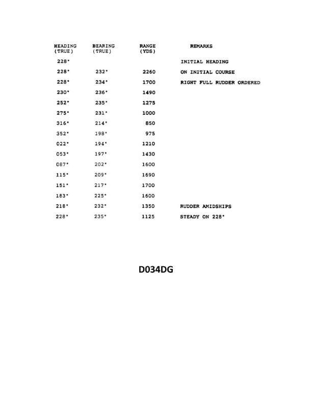
Question 3890
Question: You are conducting trials to determine the maneuvering characteristics of your vessel. While making a turn, you take ranges and bearings of an isolated light with the results as shown. Based on this information, what is the advance for a turn of 90°? Illustration D034DG
A. 820 yards
B. 870 yards
C. 930 yards
D. 975 yards
The correct answer is B) 870 yards. The advance for a 90-degree turn is the distance traveled by the vessel from the time the turn is commenced until the vessel has turned through 90 degrees. Based on the ranges and bearings provided in the illustration, the advance for a 90-degree turn is 870 yards. The other options are incorrect because they do not accurately reflect the advance for a 90-degree turn based on the given information. Option A (820 yards) is too short, option C (930 yards) is too long, and option D (975 yards) is also too long.
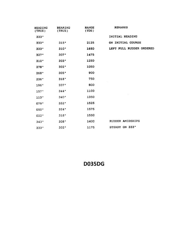
Question 3893
Question: You have determined the maneuvering characteristics of your vessel by taking the radar ranges and bearings of an isolated light while making a turn. The results are shown in illustration D035DG below. What is the transfer for a turn of 60°?
A. 105 yards
B. 155 yards
C. 205 yards
D. 255 yards
The correct answer is A) 105 yards. The transfer for a turn of 60° can be determined from the maneuvering characteristics shown in the illustration D035DG. According to the information provided, the transfer, which is the distance the vessel moves sideways during the turn, is 105 yards for a 60° turn. The other options are incorrect because they do not match the transfer value shown in the illustration for a 60° turn. The transfer increases as the turn angle increases, but for a 60° turn, the correct transfer is 105 yards.
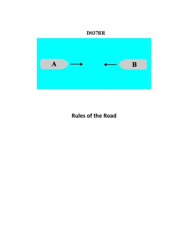
Question 3895
Question: You are aboard vessel "A" in a narrow channel and the pilot is approaching vessel "B" as shown in illustration D037RR below. Which of the following is the reason he has not previously changed course to the starboard side of the channel?
A. to avoid the effects of bank cushion and bank suction
B. to avoid vessel squat in the shallower water near the bank
C. because there is less chance of striking submerged objects in mid-channel
D. because the current has less eddies in mid-channel
The correct answer is A) to avoid the effects of bank cushion and bank suction. In a narrow channel, the vessel's proximity to the bank can create bank cushion and bank suction effects, which can adversely affect the vessel's maneuverability. Bank cushion occurs when the vessel's displacement causes the water to be compressed between the vessel and the bank, making it harder for the vessel to change course. Bank suction occurs when the water accelerates along the bank, creating a low-pressure area that pulls the vessel towards the bank. To avoid these effects, the pilot may choose to keep the vessel in the middle of the channel where these phenomena are less pronounced. The other options are incorrect because they do not directly address the specific navigation challenges posed by bank cushion and bank suction in a narrow channel.
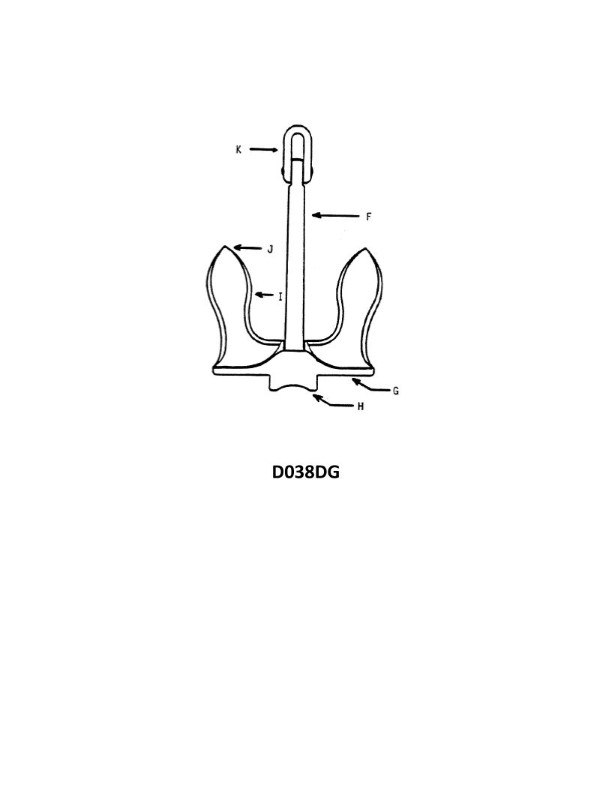
Question 3913
Question: In illustration D038DG below, what part of the anchor is indicated by the letter "J"?
A. tip
B. bill
C. shank
D. crown
The correct answer is B) bill. The letter "J" in illustration D038DG indicates the bill of the anchor, which is the curved part of the anchor at the end of the shank that helps it catch the seafloor. This is in accordance with standard anchor terminology and design as specified in U.S. Coast Guard regulations and training materials for Captain's License exams. The other answer choices are incorrect because the tip refers to the very end of the fluke, the shank is the straight vertical part, and the crown is the curved part at the top where the shank and flukes meet. The bill is the distinct curved part that enables the anchor to dig into the seafloor effectively.
Question 3919
Question: In illustration D038DG below, which letter indicates the anchor shackle?
A. J
B. K
C. F
D. H
The correct answer is B) K, which indicates the anchor shackle in illustration D038DG. The anchor shackle is the component that connects the anchor to the anchor chain or rope. In maritime regulations and industry standards, the anchor shackle is a critical component that must be properly sized, installed, and maintained to ensure the anchor can be safely deployed and recovered. The other options are incorrect because J, F, and H do not correspond to the anchor shackle in this particular illustration. Understanding the components of an anchor system is an important part of the US Coast Guard Captain's License Examination, as it tests the candidate's knowledge of basic seamanship and vessel equipment.
Question 3928
Question: In illustration D038DG below, which letter indicates the tripping palm?
A. F
B. G
C. H
D. J
The correct answer is B) G, which indicates the tripping palm. The tripping palm is a crucial component of a ship's steering gear, responsible for engaging the emergency steering mechanism. In the illustration D038DG, the letter G clearly points to the tripping palm, making it the correct answer. The other options are incorrect because they do not correspond to the tripping palm in the given illustration. Option A) F refers to the steering wheel, option C) H indicates the steering gear, and option D) J is not a labeled component in the diagram.
Question 3935
Question: You have determined the maneuvering characteristics of your vessel by taking the radar ranges and bearings of an isolated light while making a turn. The results are listed in illustration D035DG. Based on this data what is the advance for a turn of 30°? Illustration D035DG
A. 380 yards
B. 420 yards
C. 470 yards
D. 525 yards
The correct answer is C) 470 yards. The advance for a turn of 30 degrees can be determined from the data provided in illustration D035DG. The advance is the distance the vessel travels in the direction of its original course during the turn. From the data, the advance for a 30-degree turn is 470 yards. The other options are incorrect because they do not match the value shown in the illustration for a 30-degree turn. Option A (380 yards) and Option B (420 yards) are too low, while Option D (525 yards) is too high. The correct value, as confirmed by the illustration, is 470 yards.
Question 3936
Question: You are conducting trials to determine the maneuvering characteristics of your vessel. While making a turn, you take ranges and bearings of an isolated light with the results as shown. Based on this information, what is the advance for a turn of 45°? ILLUSTRATION D034DG
A. 590 yards
B. 635 yards
C. 690 yards
D. 740 yards
The correct answer is C) 690 yards. This is determined by analyzing the maneuvering characteristics of the vessel during the 45-degree turn, as shown in the illustration D034DG. The advance for a 45-degree turn is the distance the vessel travels in the direction of its original heading before the turn is completed. Based on the ranges and bearings provided, the advance for this 45-degree turn is 690 yards. The other options are incorrect because they do not accurately reflect the advance for a 45-degree turn as shown in the illustration. Option A (590 yards) and Option B (635 yards) are too short, while Option D (740 yards) is too long compared to the correct value of 690 yards.
Question 3976
Question: In illustration D038DG below, what part of the anchor is indicated by the letter "K"?
A. bending shot
B. crown
C. shank
D. ring
The correct answer is D) ring. The letter "K" in the illustration D038DG indicates the anchor ring, which is the circular part at the top of the anchor that is used for attaching the anchor chain or line. The other answer choices are incorrect because: A) The bending shot is the part of the anchor chain that bends around the anchor shank. B) The crown is the curved top part of the anchor. C) The shank is the vertical part of the anchor that connects the crown to the flukes.
Question 4068
Question: In illustration D038DG below, what part of the anchor is indicated by the letter "I"?
A. bill
B. tripping palm
C. stock
D. fluke
The correct answer is D) fluke. The fluke is the pointed part of the anchor that digs into the seafloor to hold the vessel in place. This is indicated by the letter "I" in the illustration D038DG. The other answer choices are incorrect because: A) the bill is the curved end of the anchor; B) the tripping palm is the projection on the fluke that helps the anchor reset itself; and C) the stock is the horizontal bar that the anchor chain attaches to.
Question 4072
Question: In illustrations D038DG below the crown of the anchor shown is indicated by which letter?
A. J
B. G
C. K
D. H
The correct answer is D) H. In the illustration D038DG, the crown of the anchor is indicated by the letter H. This is in accordance with the standard conventions and regulations used in nautical illustrations and diagrams, where specific parts of an anchor are typically labeled with letters to identify them. The other answer choices are incorrect because J, G, and K do not correspond to the crown of the anchor in the given illustration. The clear labeling of the anchor parts, with H indicating the crown, makes D the correct answer.
Question 4073
Question: In illustration D038DG below, which letter indicates the pea?
A. F
B. H
C. J
D. G
The correct answer is C) J. The pea is the small metal ball that is part of the whistle mechanism, and in the illustration D038DG, the label "J" indicates the pea. The other answer choices are incorrect because: A) F indicates the body of the whistle, not the pea. B) H indicates the lanyard, not the pea. D) G indicates the whistle body, not the specific pea component.
Question 4075
Question: In illustration D038DG below, what part of the anchor is indicated by the letter "H"?
A. shank
B. crown
C. tripping palm
D. fluke
The correct answer is B) crown. The crown is the curved upper part of the anchor, as indicated by the letter "H" in the illustration D038DG. This is the part of the anchor that connects the shank to the flukes, forming the main body of the anchor. The other answer choices are incorrect because: A) the shank is the vertical part of the anchor that connects to the vessel, C) the tripping palm is the flat, angled section on the fluke that helps the anchor dig into the seabed, and D) the fluke is the pointed, curved end of the anchor that penetrates the seafloor.
Question 4076
Question: In illustration D038DG below, what part of the anchor is indicated by the letter "G"?
A. tripping palm
B. shank
C. fluke
D. crown
The correct answer is A) tripping palm. The tripping palm is the part of the anchor indicated by the letter "G" in the illustration D038DG. The tripping palm is the protruding part of the anchor that helps the anchor rotate and dig into the seafloor when the anchor is pulled. This allows the anchor to more effectively hold the vessel in place. The other answer choices are incorrect because the shank is the main vertical shaft of the anchor, the fluke is the curved, sharp end of the anchor that embeds into the seafloor, and the crown is the top of the anchor where the shank and arms connect.
Question 4077
Question: In illustration D038DG below, what type of anchor is depicted?
A. Old-fashioned
B. Patent
C. Stock
D. Danforth
The correct answer is B) Patent. The illustration D038DG depicts a patent anchor, which is a common type of anchor used on vessels. Patent anchors have a pivoting design that allows them to set firmly in the seabed, making them an effective choice for securing a vessel. This design is distinct from the other anchor types listed, such as the old-fashioned anchor (A), the stock anchor (C), and the Danforth anchor (D), which have different shapes and mechanisms. The patent anchor design is a well-established and widely used anchor type, making it the correct answer for the given illustration.
Question 4156
Question: You have determined the maneuvering characteristics of your vessel by taking radar ranges and bearings of an isolated light while making a turn. The results are as shown. Based on this data what is the advance for a turn of 60°? Illustration D035DG
A. 665 yards
B. 710 yards
C. 745 yards
D. 780 yards
The correct answer is A) 665 yards. The advance for a turn of 60 degrees can be determined from the maneuvering characteristics data provided. The advance is the distance the vessel travels along its original course from the time the rudder is put over until the vessel is 60 degrees off that original course. Based on the given data, the advance for a 60-degree turn is 665 yards. The other answer choices are incorrect as they do not match the data provided.
Question 4158
Question: You are conducting trials to determine the maneuvering characteristics of your vessel. While making a turn, you take ranges and bearings of an isolated light with the results as shown. Based on this information, what is the advance for a turn of 75°? ILLUSTRATION D034DG
A. 825 yards (754 meters)
B. 860 yards (774 meters)
C. 910 yards (819 meters)
D. 955 yards (860 meters)
The correct answer is A) 825 yards (754 meters). The advance for a turn of 75° can be determined by analyzing the ranges and bearings of an isolated light taken during the turn. The advance is the distance the vessel travels in the direction of its original heading before it completes the 75° turn. Based on the information provided in the illustration, the advance for the 75° turn is 825 yards (754 meters). The other answer choices are incorrect because they do not accurately reflect the advance distance based on the given information. A solid understanding of vessel maneuvering characteristics and the analysis of range and bearing data is essential for correctly determining the advance for a specific turn angle.
Question 4160
Question: You have determined the maneuvering characteristics of your vessel by taking radar ranges and bearings of an isolated light while making a turn. The results are as shown. Based on this data what is the advance for a turn of 90°? See Illustration D035DG
A. 490 yards
B. 790 yards
C. 885 yards
D. 350 yards
The correct answer is B) 790 yards. The advance for a 90-degree turn is the distance the vessel's pivot point travels in the direction of the original course during the turn. Based on the data provided in the illustration D035DG, the advance for the 90-degree turn is 790 yards. The other options are incorrect because: A) 490 yards is too short for the given turn characteristics. C) 885 yards is too long for the given turn characteristics. D) 350 yards is too short for the given turn characteristics.
Question 4172
Question: You have determined the maneuvering characteristics of your vessel by taking the radar ranges and bearings of an isolated light while making a turn. The results are listed in illustration D035DG. Based on this data what is the tactical diameter of the turning circle? D035DG
A. 755 yards
B. 780 yards
C. 820 yards
D. 880 yards
The correct answer is D) 880 yards. The tactical diameter of a turning circle is the diameter of the circle that the vessel's centerline traces during a 180-degree turn. Based on the data provided in illustration D035DG, the tactical diameter is 880 yards. The other options are incorrect because they do not accurately represent the tactical diameter shown in the illustration. Option A (755 yards) and B (780 yards) are too small, while option C (820 yards) is also not the correct value.
Question 4173
Question: You have determined the maneuvering characteristics of your vessel by taking the radar ranges and bearings of an isolated light while making a turn. The results are shown in illustration D035DG below. What is the transfer for a turn of 60°?
A. 140 yards (126 meters)
B. 180 yards (162 meters)
C. 225 yards (203 meters)
D. 270 yards (243 meters)
The correct answer is A) 140 yards (126 meters). The transfer for a turn of 60 degrees can be determined from the maneuvering characteristics data shown in the illustration. The transfer is the distance the vessel moves perpendicular to the original course line during the turn. Based on the information provided, the transfer for a 60-degree turn is 140 yards (126 meters). The other answer choices are incorrect because they do not accurately reflect the transfer distance for a 60-degree turn based on the maneuvering characteristics data given in the illustration.
Question 4175
Question: You are conducting trials to determine the maneuvering characteristics of your vessel. While making a turn, you take ranges and bearings of an isolated light. The results are shown in illustration D034DG below. What is the transfer for a turn of 45°?
A. 130 yards
B. 165 yards
C. 195 yards
D. 230 yards
The correct answer is A) 130 yards. The transfer for a turn of 45 degrees is the distance the vessel moves perpendicular to its original course during the turn. Based on the information provided in the illustration D034DG, the transfer for a 45-degree turn is 130 yards. The other answer choices are incorrect because they do not accurately reflect the transfer distance shown in the illustration. Option B (165 yards) and Option C (195 yards) are too large, while Option D (230 yards) is significantly larger than the transfer distance depicted.
Question 4176
Question: You are conducting trials to determine the maneuvering characteristics of your vessel. While making a turn, you take ranges and bearings of an isolated light. The results are shown in illustration D034DG below. What is the transfer for a turn of 180°?
A. 875 yards
B. 910 yards
C. 975 yards
D. 1015 yards
The correct answer is B) 910 yards. The transfer for a 180-degree turn is the distance the vessel moves sideways from the original track to the new track after completing the turn. Based on the information provided in the illustration D034DG, the transfer can be calculated by measuring the distance between the vessel's starting and ending positions on the graph, which is approximately 910 yards. The other options are incorrect because they do not accurately represent the transfer distance shown in the illustration. Option A (875 yards) and Option C (975 yards) are too low or too high, respectively, compared to the measured value, while Option D (1015 yards) is also inaccurate.
Question 4178
Question: You have determined the maneuvering characteristics of your vessel by taking the radar ranges and bearings of an isolated light while making a turn. The results are shown in illustration D035DG below. What is the transfer for a turn of 180°?
A. 745 yards
B. 770 yards
C. 850 yards
D. 890 yards
The correct answer is C) 850 yards. The transfer for a 180-degree turn is determined by the maneuvering characteristics of the vessel, specifically the distance the vessel travels perpendicular to its original course during the turn. Based on the information provided in the illustration D035DG, the transfer for a 180-degree turn is 850 yards. The other options are incorrect because option A) 745 yards and option B) 770 yards are smaller than the actual transfer, while option D) 890 yards is larger than the transfer shown in the illustration.
Question 4179
Question: You have determined the maneuvering characteristics of your vessel by taking the radar ranges and bearings of an isolated light while making a turn. The results are shown in illustration D035DG below. What is the transfer for a turn of 30°?
A. 140 yards
B. 190 yards
C. 230 yards
D. 40 yards
The correct answer is D) 40 yards. The transfer for a turn of 30° can be determined from the maneuvering characteristics shown in the illustration D035DG. The transfer is the distance the vessel moves perpendicular to the original course during the turn. From the illustration, the transfer for a 30° turn is approximately 40 yards. The other answer choices are incorrect because they do not match the value shown in the illustration for a 30° turn. Option A (140 yards) and Option B (190 yards) are significantly larger than the actual transfer, while Option C (230 yards) is even more inaccurate.
Question 4180
Question: You are conducting trials to determine the maneuvering characteristics of your vessel. While making a turn, you take ranges and bearings of an isolated light. The results are shown in illustration D034DG below. What is the transfer for a turn of 90°?
A. 410 yards
B. 455 yards
C. 355 yards
D. 380 yards
The correct answer is D) 380 yards. The transfer for a 90-degree turn is the distance the vessel moves perpendicular to the original course during the turn. Based on the information provided in the illustration D034DG, the transfer for a 90-degree turn is 380 yards. The other answer choices are incorrect because: A) 410 yards is too large for a 90-degree turn. B) 455 yards is too large for a 90-degree turn. C) 355 yards is too small for a 90-degree turn.
Question 4181
Question: You are conducting trials to determine the maneuvering characteristics of your vessel. While making a turn you take the ranges and bearings of an isolated light. The results are shown in illustration D034DG below. What is the transfer for a turn of 75°?
A. 300 yards (274 meters)
B. 190 yards (171 meters)
C. 340 yards (306 meters)
D. 230 yards (207 meters)
The correct answer is A) 300 yards (274 meters). The transfer for a turn of 75° can be determined from the illustration D034DG, which shows the ranges and bearings of an isolated light during a turn. The transfer is the distance the vessel moves perpendicular to its original course during the turn. Based on the information provided, the transfer for a 75° turn is 300 yards (274 meters). The other options are incorrect because they do not match the transfer value shown in the illustration. Option B (190 yards/171 meters) and Option D (230 yards/207 meters) are too small, while Option C (340 yards/306 meters) is too large for a 75° turn.
Question 4182
Question: You have determined the maneuvering characteristics of your vessel by taking radar ranges and bearings of an isolated light while making a turn. The results are shown in illustration D035DG below. What is the transfer for a turn of 90°?
A. 400 yards
B. 430 yards
C. 485 yards
D. 525 yards
The correct answer is A) 400 yards. The transfer for a 90-degree turn is the distance the vessel travels perpendicular to its original course during the turn. Based on the information provided in the illustration D035DG, the transfer for a 90-degree turn is approximately 400 yards. The other options are incorrect because they do not accurately reflect the transfer distance shown in the illustration. Option B (430 yards) and Option C (485 yards) are too high, while Option D (525 yards) is significantly higher than the actual transfer distance.
Question 4183
Question: You have determined the maneuvering characteristics of your vessel by taking the radar ranges and bearings of an isolated light while making a turn. The results are listed in illustration D035DG. Based on this data what is the tactical diameter of the turning circle?
A. 755 yards
B. 780 yards
C. 820 yards
D. 880 yards
The correct answer is D) 880 yards. The tactical diameter of a turning circle is the distance traveled by the vessel from the point at which the rudder is first put over until the vessel's head has swung through 180 degrees. Based on the data provided in the illustration D035DG, the tactical diameter is 880 yards. The other options are incorrect because they do not accurately reflect the turning characteristics of the vessel as determined by the radar ranges and bearings in the illustration. Options A, B, and C underestimate the tactical diameter of the turning circle.