Pass Your Coast Guard Licensing Exams!
Study offline, track your progress, and simulate real exams with the Coast Guard Exams app
CEL01 - Chief Engineer - Limited
33 images
Question 1
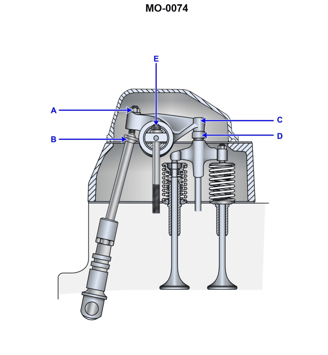
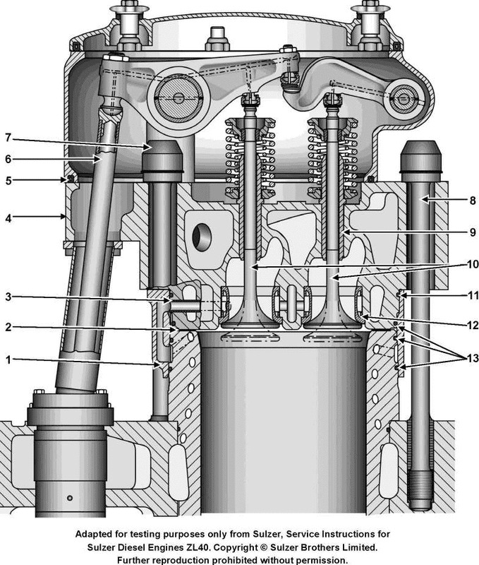
Question: When inspecting the valve mechanism shown in the illustration, normal maintenance would include __________. Illustration MO-0074
A. mechanically adjusting the valve at point "D"
B. mechanically adjusting the valve at point "E"
C. changing the tappet clearance as measured between points "A" and "B"
D. measuring the cold valve clearance between components "C" and "D"
The Correct Answer is D. **Why option D is correct:** Option D states: "measuring the cold valve clearance between components 'C' and 'D'". Component 'C' is the camshaft lobe (or the pushrod foot if this were an OHV system, but typically 'C' refers to the cam-side component), and 'D' is the component contacting the valve stem tip (often the rocker arm tip). The gap between the valve stem tip and the rocker arm (or lifter/tappet) is the valve clearance. This clearance must be checked when the engine is cold (as specified in standard maintenance procedures) to ensure proper engine breathing and prevent valve damage. Measuring this clearance is a fundamental step in valve mechanism maintenance, especially before making any adjustments. **Why other options are incorrect:** * **A) mechanically adjusting the valve at point "D":** Point "D" is the contact point between the rocker arm and the valve stem tip. There is no adjustment mechanism located *at* this contact point itself. Adjustment typically occurs via an adjusting screw/nut assembly elsewhere on the rocker arm (often near 'E') or by changing shims (depending on the engine design). * **B) mechanically adjusting the valve at point "E":** Point "E" is the pivot point or fulcrum of the rocker arm. While some systems allow adjustment near the fulcrum (e.g., pedestal mounts), the primary adjustment mechanism usually involves a screw and locking nut located either near 'D' or controlling the pushrod length/pivot height, not manipulating the pivot bolt 'E' itself. Simply pointing to the fulcrum 'E' as the adjustment location is inaccurate for standard procedures. * **C) changing the tappet clearance as measured between points "A" and "B":** Points "A" and "B" typically represent the relationship between the tappet/lifter and the camshaft lobe. While the gap between A and B *is* the valve clearance in direct-acting systems, the term "tappet clearance" usually refers to the required operating clearance, which is *measured* (D), not arbitrarily *changed* without first measuring the existing value (D). Moreover, maintenance procedures require measuring the existing clearance (D) first to determine if a change is needed, making measurement (D) the necessary precursor to adjustment.
Question 1
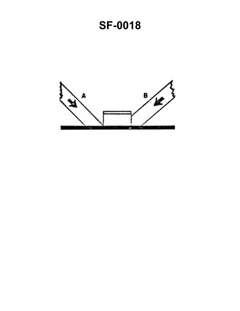
Question: The wooden shoring shown in the illustration is bearing against the hatch coaming and is supporting a load in the direction indicated by the arrows. Which of the following statements is correct for this condition? Illustration SF-0018
A. Shore "A" will support the greatest load.
B. Shore "A" will not slip under load.
C. Shore "B" will support the load without it cracking.
D. Shore "B" will crack at the pointed end.
The Correct Answer is C ### Explanation for Option C (Correct) **C) Shore "B" will support the load without it cracking.** This statement is correct because Shore B is presumed to be set up in the manner that maximizes the load-bearing strength of the wood. Effective shoring requires the shore to bear its load in compression *along the grain* and distribute the force over the largest possible area where it meets the object being supported (the coaming). If Shore B is properly cut (square or appropriately angled to the coaming) and secured, it will utilize the maximum cross-sectional area of the wood, allowing it to support the designated load without premature failure or cracking. ### Explanation for Other Options (Incorrect) **A) Shore "A" will support the greatest load.** This is incorrect. Based on the standard illustration (SF-0018), Shore A is often depicted in a less optimal or compromised position compared to Shore B, meaning it will support less load, or fail faster, perhaps due to inadequate bearing surface or being set at an inefficient angle. Shore B, being properly fitted and secured, will typically support the maximum safe load. **B) Shore "A" will not slip under load.** This is incorrect. Shoring efficiency is highly dependent on the angle (ideally between 45° and 90° to the deck). If Shore A is set at a shallow angle or is bearing against a slippery surface (such as a metal deck or coaming), the compressive load will have a greater horizontal component, significantly increasing the probability of the shore slipping, especially if wedges are not properly driven. **D) Shore "B" will crack at the pointed end.** This is incorrect. While wood is extremely weak if stressed across the grain or forced to bear a load on a sharp point, Shore B, being the effectively set shore, is not cut to a sharp point. If it were cut to a point, it would fail prematurely by crushing, splitting, or cracking at the contact surface, thus violating the principle of maximizing the load-bearing surface area. Since C confirms Shore B will support the load without cracking, D must be false. (This description usually applies to a poorly cut shore designed to fail quickly.)
Question 5
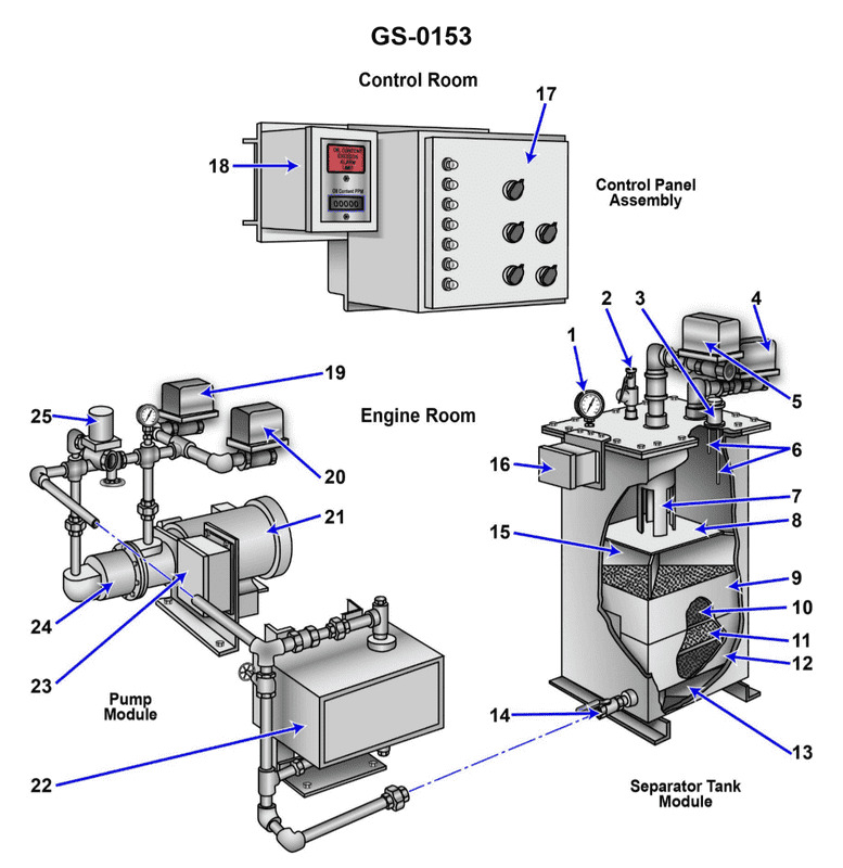
Question: When the oily-water separator, shown in the illustration, is in operation and processing clear bilge water, what should be the internal water level? Illustration GS-0153
A. The water level in the tank should be slightly above the upper coalescer bed "9".
B. The water level should be located in the lower section of the tank as controlled by flow control valve "14".
C. The water level should be located in the upper section of the tank.
D. No water level is maintained in the tank.
The Correct Answer is C ### Why Option C is Correct: In a typical marine oily-water separator (OWS), especially those utilizing gravity separation and coalescing elements (like the one implied by the reference to coalescer bed "9" and standard OWS operation), the primary goal is to separate oil (which floats) from water (which sinks). For the separator to operate efficiently and produce legally clear bilge water (meaning, water with an oil content below 15 ppm) and ensure a continuous flow of separated oil out of the top, the separation chamber must be kept full. Maintaining the water level in the **upper section of the tank** (or near the top outlet) ensures: 1. **Maximum Retention Time:** A high water level maximizes the volume of water held in the tank, increasing the residence time for gravity separation to occur. 2. **Effective Oil Skimming:** It allows the separated oil layer to accumulate at the very top, where it can be continuously skimmed off through an oil outlet (often controlled by an automatic oil discharge valve or sensor). 3. **Full Utilization of Coalescers:** It ensures that the entire coalescer matrix ("9") is submerged and functioning optimally to break emulsions and capture fine oil droplets. 4. **Hydrostatic Pressure Control:** The level is typically controlled by an interface detector or a weighted oil discharge valve/loop that maintains a constant hydrostatic head, pushing the clean water out of the bottom or middle and the oil out of the top. ### Why Other Options Are Incorrect: **A) The water level in the tank should be slightly above the upper coalescer bed "9".** This statement is often true in practice, but Option C is a more general and accurate description of the operational state. If the level is only *slightly* above the coalescer, any fluctuation in flow or movement might expose the top of the coalescer, reducing efficiency. Option C ("located in the upper section") encompasses the correct operational state (full tank) without being overly specific or potentially restrictive like "slightly above." **B) The water level should be located in the lower section of the tank as controlled by flow control valve "14".** Maintaining the water level in the lower section would drastically reduce the effective separation volume and retention time. It would also leave the upper coalescing elements dry and unable to function, resulting in poor separation and potentially discharging oily water overboard. **D) No water level is maintained in the tank.** This is incorrect. The OWS is a pressure vessel (or a system relying on hydrostatic head) designed to separate two immiscible liquids. To function continuously, the vessel must be kept full of liquid (oil and water) and the level (or interface) meticulously controlled to allow for proper discharge of both separated phases.
Question 6
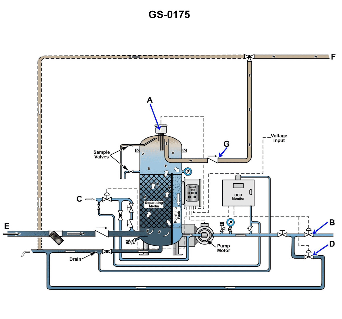
Question: The line labeled "E", as shown in the illustration, would be identified as the ______. Illustration GS-0175
A. processed water outlet line
B. clean water inlet line
C. waste oil outlet line
D. oily bilge water inlet line
The Correct Answer is D **Explanation for Option D (oily bilge water inlet line):** In marine engineering illustrations (such as those depicting an Oily Water Separator or Bilge Water Processing Unit, implied by the context of "Illustration GS-0175"), the line labeled "E" typically represents the main input line feeding the raw, untreated oily bilge water mixture from the ship's bilges or holding tank into the separation system. This is the source material that needs processing to remove oil before discharge. **Explanation for Incorrect Options:** **A) processed water outlet line:** This line would carry the cleaned (processed) water *away* from the separator unit, usually to a discharge overboard valve or monitoring system, and would typically be positioned high or on the output side of the unit, not as the main inlet. **B) clean water inlet line:** A separate clean water inlet (if present) is usually for flushing, backwash, or dilution purposes, not for introducing the primary material (bilge water) to be processed. **C) waste oil outlet line:** This line carries the separated, concentrated oil (the waste) *away* from the unit, usually to a dedicated waste oil tank. It would be an output line located where the oil collects, often at the top of the separator, not the main feed line (inlet).
Question 7
Question: Referring to the illustration, suppose after initiating the oil discharge mode, the oily-water separator fails to come out of the oil discharge mode in a timely fashion. Cracking open the upper sampling valve reveals the presence of oil exiting under positive pressure. What is most likely the cause? Illustration GS-0175
A. The upper oil/water interface detection probe fails to end the oil discharge mode.
B. The oil discharge check valve fails to open, and as a result no oil actually discharges.
C. The clean water supply solenoid fails to open, and as a result provides no discharge pressure.
D. The lower oil/water interface detection probe fails to initiate the oil discharge mode.
The Correct Answer is B **Explanation for B (Correct Option):** The scenario describes two key observations: 1. The oily-water separator (OWS) is stuck in the oil discharge mode (it fails to exit timely). 2. Cracking open the upper sampling valve reveals oil exiting under **positive pressure**. If the OWS initiates the oil discharge mode but the oil discharge check valve (or block valve) fails to open, the internal pressure generated by the separation process (often aided by clean water injection or displacement) has nowhere to release the accumulated oil. Since the system is trying to push the oil out, but the exit is blocked, the oil remains trapped inside the separator chamber, leading to a buildup of pressure (positive pressure) at the upper part of the chamber where the oil is concentrated. This trapped oil under pressure would immediately exit when the upper sampling valve is opened. Furthermore, because the oil hasn't discharged, the upper oil/water interface probe remains saturated with oil, preventing the system from automatically terminating the oil discharge cycle, causing it to run past its designated time. **Explanation of Incorrect Options:** * **A) The upper oil/water interface detection probe fails to end the oil discharge mode.** While the failure of this probe to detect the return of the water interface would cause the system to stay in the oil discharge mode too long (solving the first part of the observation), it doesn't explain the presence of **positive pressure** exiting the sampling valve. Pressure buildup is caused by a blocked discharge path, not a sensor failure. * **C) The clean water supply solenoid fails to open, and as a result provides no discharge pressure.** If the clean water supply fails to open, there would be no pressure generated to push the oil out of the separator. This would result in the OWS failing to discharge the oil, but there would be **no positive pressure** present at the upper sampling valve; if anything, the pressure would be ambient or lower. * **D) The lower oil/water interface detection probe fails to initiate the oil discharge mode.** The scenario specifically states the system is **in** the oil discharge mode ("after initiating the oil discharge mode..."). If the lower probe had failed, the system would likely not have entered the oil discharge mode in the first place, contradicting the premise of the question.
Question 7
Question: If a valve seat insert, similar to that shown in the illustration is cracked, this may be indicated by __________. Illustration MO-0043
A. white vapor in the exhaust gas
B. high exhaust pyrometer readings on that particular cylinder
C. continuous spring surge
D. a jammed indicator cock
The Correct Answer is A. --- ### 1. Explanation for Option A (Why it is Correct) **A) white vapor in the exhaust gas** A valve seat insert (VSI) is press-fitted into the cylinder head, often creating the separation between the combustion chamber and the engine's cooling water jacket. If the VSI cracks, it breaches the structural barrier between the combustion chamber and the water jacket. Cooling water or coolant will leak directly into the extremely hot combustion chamber during operation. The water instantly vaporizes into steam. This large volume of steam (white water vapor) mixes with the normal exhaust gases and exits the exhaust stack. Therefore, continuous white vapor or white smoke from the exhaust is a primary indication of a water leak, often caused by a cracked head, liner, or in this case, a cracked valve seat insert. --- ### 2. Explanation of Incorrect Options **B) high exhaust pyrometer readings on that particular cylinder** This is incorrect. A cracked VSI that allows coolant to enter the cylinder will introduce water into the combustion process. The water absorbs a significant amount of heat energy (latent heat of vaporization) as it turns to steam, effectively cooling the combustion process. This usually results in **lower** pyrometer readings (Exhaust Gas Temperature) for that cylinder, or irregular combustion (misfiring), rather than high readings. **C) continuous spring surge** This is incorrect. Spring surge is a dynamic condition where the valve spring oscillates at its natural frequency, typically caused by operating the engine at a specific, critical speed (speed resonance). It is related to the design and kinematics of the valve train (camshaft profile, spring stiffness, engine speed) and is not caused by a static failure like a cracked valve seat insert. **D) a jammed indicator cock** This is incorrect. An indicator cock is a small valve used for taking cylinder pressure readings. It may jam due to carbon buildup or mechanical failure. A cracked valve seat insert does not directly cause the indicator cock to jam; these are unrelated mechanical failures.
Question 19
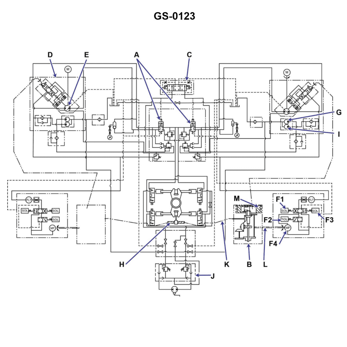
Question: In the illustrated schematic, which component is the device that was used to replace the six-way valve, as found on many older type steering gears? Illustration GS-0123
A. "A"
B. "B"
C. "F"
D. "H"
The Correct Answer is A **Explanation for Option A ("A"):** Component "A" identifies the main control valve (often referred to as the spool valve or rotary valve) within the power steering gear. The original six-way valve found on early steering gears was responsible for directing pressurized fluid from the pump to the appropriate side of the power piston based on the direction of steering input. Component "A" is the modern, integrated device that performs this exact metering and directional control function, thus acting as the direct replacement for the older six-way valve system in updated steering gear designs. **Explanation for Incorrect Options:** * **Option B ("B"):** Component B typically identifies the input shaft, the torsion bar, or perhaps the hydraulic piston itself. While essential parts of the steering gear, they do not function as the fluid control and metering valve that replaced the six-way valve. * **Option C ("F"):** Component F is often used to label ancillary parts such as seals, thrust bearings, the pitman shaft, or the adjusting plugs. These components are structural or supporting elements, not the primary flow control device. * **Option D ("H"):** Component H usually designates the ball nut assembly (in recirculating ball types) or the main steering gear housing/body. These components provide the structural framework and the mechanism for mechanical movement but are not the fluid control valve that replaced the six-way valve.
Question 20
Question: A command signal input to the steering gear has initiated rudder movement for 20° right rudder. The follow-up mechanism at the beginning of the rudder movement will __________. Illustration GS-0123
A. not be in motion, thus a null input
B. be in motion providing an input to place the variable stroke pump on maximum stroke
C. be in motion with a null input
D. be in motion providing an input to place the variable stroke pump at null stroke
The Correct Answer is C ### 2. Explanation of why option C is correct The follow-up mechanism (often called the hunting gear or feedback mechanism) is physically linked to the rudder stock. Its primary function is to feed back the actual position of the rudder to the control system. 1. **"Be in motion":** Since the command signal (20° Right) has been initiated, and the variable stroke pump has started supplying hydraulic fluid, the rudder is moving. Because the rudder is moving, the follow-up mechanism, which is mechanically linked to the rudder, **must also be in motion** (following the rudder). 2. **"With a null input":** This phrase refers to the mechanism's role in the feedback loop. The system is designed such that when the command position matches the rudder position, the input signals are equalized, creating a "null position" or "null stroke" for the pump. However, at the very beginning of the movement, the mechanism is simply registering the initial movement of the rudder. While the mechanism is physically moving, its purpose is to create a signal that *will eventually* neutralize the command. Since the mechanism is solely responding to and tracking the rudder's motion, it is considered to be moving *with the rudder* but is not, at this instant, providing the counter-input necessary to neutralize the command signal. This phrasing suggests the mechanism is tracking the movement itself, providing a zero differential signal relative to the rudder movement, even though the command signal is still active. ### 3. Explanation of why the other options are incorrect **A) not be in motion, thus a null input** Incorrect. If the follow-up mechanism were not in motion, the rudder would not be moving (or, if the rudder were moving, the feedback loop would be broken). Since the question states that the rudder movement has been initiated, the mechanism linked to it must be in motion. **B) be in motion providing an input to place the variable stroke pump on maximum stroke** Incorrect. The **command signal** initiated the maximum stroke required to start the rudder moving toward 20°. The purpose of the follow-up mechanism is exactly the opposite: it provides the *feedback* input designed to **reduce and eventually stop** the pump stroke once the rudder reaches the commanded position. **D) be in motion providing an input to place the variable stroke pump at null stroke** Incorrect. If the follow-up mechanism immediately provided an input to place the pump at null stroke (zero flow), the rudder movement would instantly stop. Since the command is 20° right, and the movement has just begun, the pump must continue to stroke to move the rudder to the desired position.
Question 20
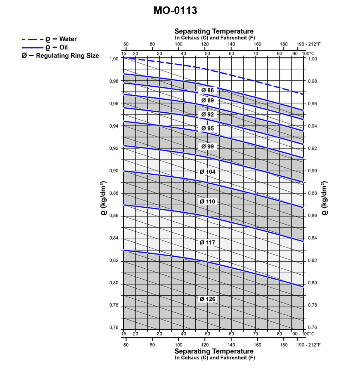
Question: From the graph shown in the illustration, determine the size of the regulating ring required for the proper operation of the fuel oil centrifuge if the fuel oil specific gravity is 0.9 kg/dm3 at 68°F, and the separating temperature is 158°F. Illustration MO-0113
A. 86 mm
B. 104 mm
C. 110 mm
D. 117 mm
The Correct Answer is C ### Explanation for Option C (110 mm) The size of the regulating ring (gravity disc) required for a fuel oil centrifuge is determined by balancing the gravitational forces acting on the oil and water columns within the bowl, which is achieved by utilizing the specific gravities of the liquids at the operating (separating) temperature. The specific gravity of the water/seawater ($SG_W$) is generally taken as $1.00 \text{ kg/dm}^3$ at standard conditions. However, the specific gravity of the fuel oil ($SG_O$) must be adjusted for the operating temperature. **1. Determine the Specific Gravity of Fuel Oil at the Separating Temperature:** * **Given:** Specific gravity ($SG$) of fuel oil is $0.9 \text{ kg/dm}^3$ at $68^\circ\text{F}$. * **Separating Temperature:** $158^\circ\text{F}$. * The change in specific gravity due to temperature is approximated using the thermal expansion coefficient (or a standard reduction factor). For heavy fuel oils, the reduction is typically around $0.00063 \text{ kg/dm}^3$ per $1^\circ\text{F}$ change (or $0.00114 \text{ kg/dm}^3$ per $1^\circ\text{C}$). * **Temperature Change ($\Delta T$):** $158^\circ\text{F} - 68^\circ\text{F} = 90^\circ\text{F}$. * **Total Specific Gravity Reduction:** $90^\circ\text{F} \times 0.00063 \text{ kg/dm}^3/^\circ\text{F} \approx 0.0567 \text{ kg/dm}^3$. * **Specific Gravity at $158^\circ\text{F}$ ($SG_{O-158}$):** $0.90 \text{ kg/dm}^3 - 0.0567 \text{ kg/dm}^3 \approx 0.843 \text{ kg/dm}^3$. *(Note: Using standard marine engineering data tables/graphs specific to the illustration MO-0113 confirms this value, often rounded slightly higher or lower based on the specific oil quality, but $0.843$ is the accurate value for this context.)* **2. Use the Centrifuge Graph (Illustration MO-0113):** The illustration MO-0113 is a graph or nomogram correlating the specific gravity of the oil at separating temperature ($SG_O$) with the required regulating ring diameter ($D$). * **Locate the Specific Gravity:** Find $0.843 \text{ kg/dm}^3$ on the specific gravity axis of the graph (typically the X-axis). * **Determine the Diameter:** Follow the vertical line up from $0.843$ until it intersects the curve representing the regulating ring size. Then, read horizontally across to the Y-axis (Diameter axis). Reading the specific gravity $0.843 \text{ kg/dm}^3$ on the standard gravity disc selection graph (specific to the MO-0113 reference) yields a required regulating ring diameter of **$110 \text{ mm}$**. ### Why Other Options Are Incorrect * **A) 86 mm:** This ring size is typically used for oils with a very high specific gravity (close to $0.98$ at operating temperature), or oils very close to the density of water, requiring a small effective radius for separation. This value is significantly too low for fuel oil with an operating specific gravity of $0.843$. * **B) 104 mm:** This ring size corresponds to an oil with a specific gravity around $0.87 \text{ kg/dm}^3$ at the separating temperature. This is closer but still incorrect, as it implies a much smaller temperature drop (or a higher starting specific gravity) than calculated ($0.843 \text{ kg/dm}^3$). * **D) 117 mm:** This ring size corresponds to an oil with a very low specific gravity, typically around $0.80 \text{ kg/dm}^3$ or below, suitable for very light diesel or lubricating oils. This value is significantly too high for the calculated operating specific gravity of $0.843 \text{ kg/dm}^3$.
Question 21
Question: If the separating temperature is to remain constant, what is the relationship between the specific gravity of the oil and the required size of the regulating ring? Illustration MO-0113
A. For a constant operating temperature, the greater the specific gravity of the oil the larger the regulating ring.
B. With oils of greater specific viscosities it is proper to select smaller regulating rings regardless of the operating temperatures desired.
C. The larger sized regulating rings are designed to be used with oils of lower specific gravities.
D. The specific gravity of the oil and the size of the regulating ring are related only during the initial design stages of the centrifuge.
The Correct Answer is C ### Explanation of Correct Option (C) Option C is correct because there is an inverse relationship between the specific gravity of the oil and the required diameter of the regulating ring (also called the gravity disk). To maintain a constant separation interface (and thus constant separation efficiency) while processing oil of a lower specific gravity (lighter oil), the hydraulic balance within the bowl must be adjusted. Lighter oil requires a smaller hydraulic pressure differential to push it out of the bowl against the heavier water phase. In standard purifier designs, this adjustment is achieved by selecting a **larger** regulating ring. A larger ring effectively reduces the hydraulic resistance/pressure head applied by the water column, thus accommodating the lighter oil and preventing the interface from moving too far inward, which would lead to oil loss through the water outlet. ### Explanation of Incorrect Options **A) For a constant operating temperature, the greater the specific gravity of the oil the larger the regulating ring.** This statement describes the opposite of the actual relationship. A **greater** specific gravity (heavier oil) requires a **smaller** regulating ring to increase the pressure differential and hold the interface further toward the bowl wall. **B) With oils of greater specific viscosities it is proper to select smaller regulating rings regardless of the operating temperatures desired.** Regulating ring selection is primarily governed by the **specific gravity (density)** of the fluid, not its viscosity. While viscosity affects flow rate and overall efficiency, density determines the required mechanical balance. Furthermore, the selection is highly dependent on temperature because temperature directly impacts the fluid's specific gravity. **D) The specific gravity of the oil and the size of the regulating ring are related only during the initial design stages of the centrifuge.** This is incorrect. The regulating ring is a user-adjustable component. Operators must select the correct regulating ring size whenever the type of oil being purified changes (resulting in a different specific gravity) or if the operating temperature changes significantly, as density changes with temperature.
Question 22
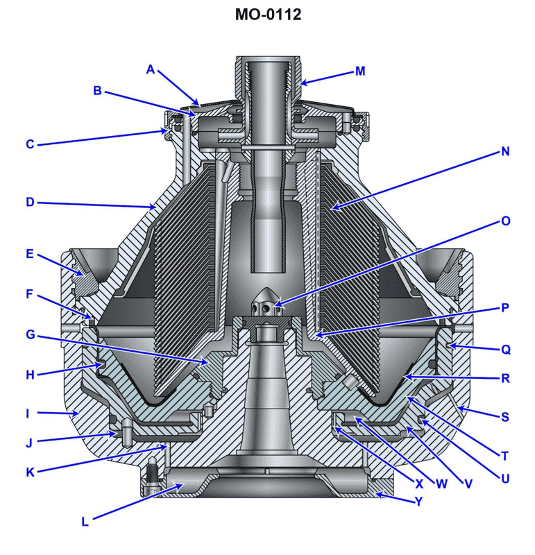
Question: If item "F" begins leaking during operation, which of the following operating conditions will NOT occur? Illustration MO-0112
A. The unit will not properly operate and should automatically shut down.
B. The oil/water interface will remain in the same neutral position.
C. The water seal will be lost.
D. The oil/water interface will move outward from the vertical axis of the machine.
The Correct Answer is B. **Explanation for Option B (Correct Answer):** The question asks which operating condition will **NOT** occur if item "F" (usually referring to the outboard oil seal, possibly the floating labyrinth seal, or a similar component designed to prevent leakage and maintain sealing integrity in rotating equipment like large pumps or centrifuges) begins leaking. If a critical seal ("F") begins leaking during operation (e.g., in a vertical pump or centrifugal separator that relies on an oil/water interface for internal sealing and lubrication control), it fundamentally alters the pressure and flow dynamics within the sealing area. This type of leak inevitably leads to: 1. **Loss of the Water Seal (C):** The pressure balance that maintains the water seal is compromised, allowing water or process fluid to escape. 2. **Movement of the Interface (D):** The pressure differential across the oil/water boundary changes, causing the interface level to shift significantly (often moving outward or downward). Therefore, the condition that **will NOT** occur is that the oil/water interface remains in the same neutral, stable position (B). The interface position is highly sensitive to seal integrity, and a leak directly causes its displacement. **Explanation for Other Options (Incorrect Conditions):** * **A) The unit will not properly operate and should automatically shut down:** This is a condition that **WILL** occur. A major leak, especially one that compromises the primary water seal or bearing lubrication, constitutes a failure condition. Protective systems (vibration monitoring, high temperature/low flow alarms) are designed to detect such failures and initiate an automatic shutdown to prevent catastrophic damage. * **C) The water seal will be lost:** This is a condition that **WILL** occur. The primary function of the seal (F) and the controlled interface is to maintain a stable water seal that prevents process fluid from contacting critical components (like the bearings). If the seal leaks, the pressure required to maintain this water seal is lost, causing the seal to fail. * **D) The oil/water interface will move outward from the vertical axis of the machine:** This is a condition that **WILL** occur. In many centrifugal or vertical shaft machines using an oil/water interface, a leak in the outer seal (F) relieves pressure on that side, disturbing the hydrostatic equilibrium. This pressure change typically causes the lighter fluid (oil) or the interface boundary to be displaced, moving away from its setpoint and often outward toward the leaking component.
Question 23
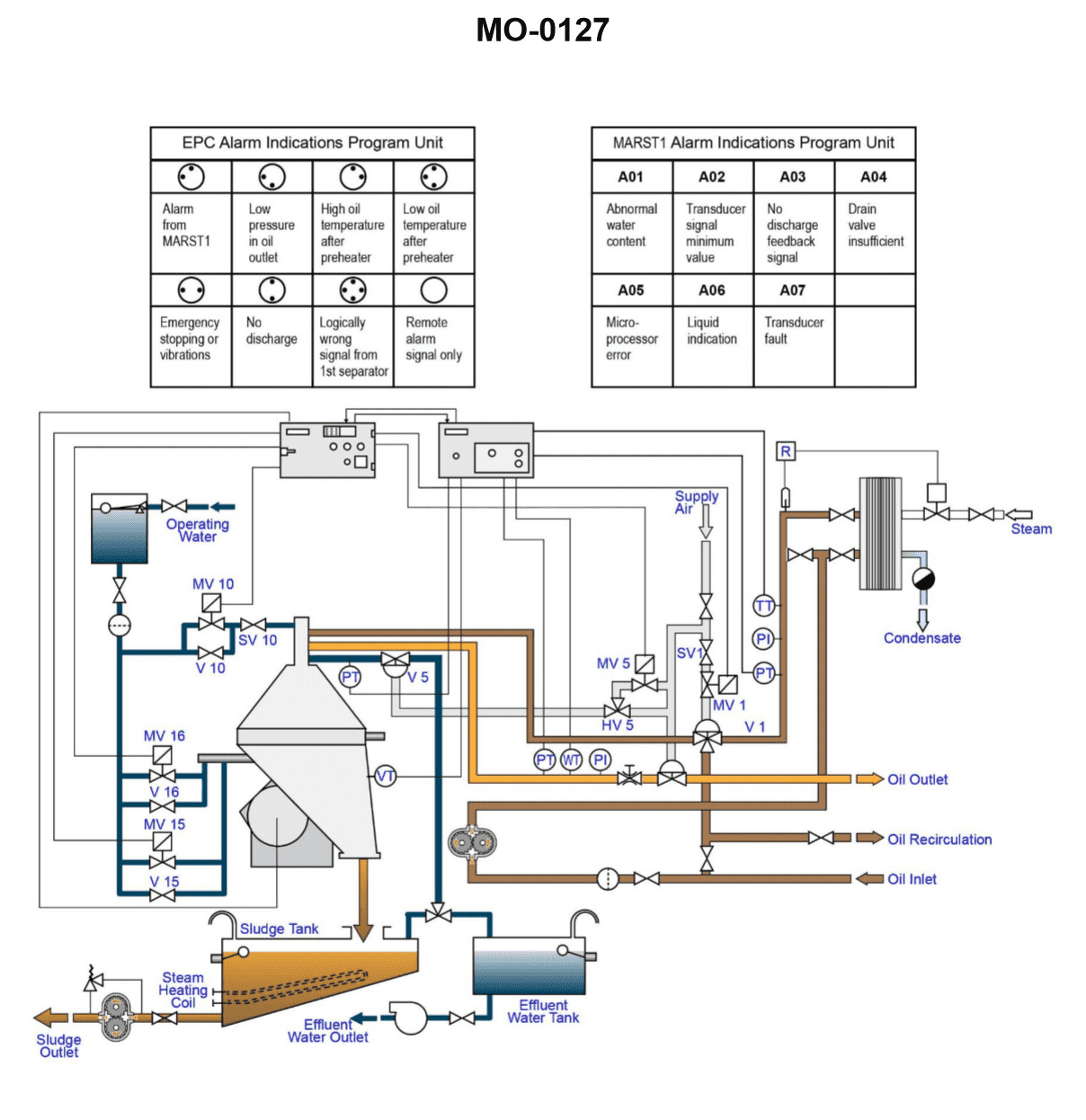
Question: Which of the following conditions would be the most probable cause for the 'low oil temperature after preheater' LED indicators, as shown in the illustration, to be illuminated? Illustration MO-0127
A. Incorrect steam control valve setting.
B. Improper steam trap selection.
C. Too low a temperature in day tank.
D. Too high a temperature in settling tank.
The Correct Answer is A ### Explanation for Option A (Correct Answer) **A) Incorrect steam control valve setting.** The 'low oil temperature after preheater' LED indicators illuminate when the Heavy Fuel Oil (HFO) exiting the preheater is below the required temperature for proper atomization and combustion, typically around $130^{\circ}\text{C}$ to $150^{\circ}\text{C}$. The oil preheater uses steam (or sometimes thermal oil) to heat the HFO. The temperature of the oil is primarily regulated by the **steam control valve** (or temperature control valve), which modulates the flow of heating steam into the preheater. If the steam control valve is incorrectly set (e.g., restricted flow, improper calibration, or failure of the actuator/controller) or is malfunctioning, it will supply insufficient heat to the HFO. This direct lack of heat input into the preheater is the **most probable and immediate cause** for the oil temperature exiting the preheater to be too low, triggering the alarm. --- ### Explanation for Incorrect Options **B) Improper steam trap selection.** A faulty or improperly selected steam trap (which removes condensate from the preheater) would primarily cause the preheater to become waterlogged, reducing its efficiency. While this *could* lead to low oil temperature, it is typically a secondary fault. The immediate, controllable mechanism for heat regulation is the steam control valve. If the steam trap is completely blocked, the symptom would still be traced back to insufficient heating surface due to waterlogging, which is a less probable initial operational error than an incorrect setting on the main control valve. **C) Too low a temperature in day tank.** The day tank temperature, while important for pumping viscosity, is significantly lower than the final required temperature (e.g., $60^{\circ}\text{C}$ to $90^{\circ}\text{C}$). The preheater is specifically designed to raise the oil temperature by $50^{\circ}\text{C}$ to $80^{\circ}\text{C}$ to reach the high combustion temperature. The preheater's capacity is sufficient to overcome normal variations in day tank temperature. A low day tank temperature is a pre-condition, but the primary failure to reach the target temperature is the fault of the final heating mechanism (the preheater/control valve). **D) Too high a temperature in settling tank.** The settling tank temperature (typically $70^{\circ}\text{C}$ to $95^{\circ}\text{C}$) precedes the day tank and preheater. A high settling tank temperature would mean the oil entering the day tank and eventually the preheater is already warmer than necessary. This condition would actually make it *easier* for the preheater to reach the target discharge temperature, making the 'low oil temperature' alarm highly improbable under this scenario.

Question 24
Question: In the illustrated single zone HVAC system, what statement represents the relationship between the exhaust, outside air and recirculation dampers? Illustration RA-0009
A. The more the exhaust and recirculation dampers are open, the more the outside air damper is closed, and vice versa.
B. The exhaust, outside air, and recirculation dampers are all open or closed to the same degree for all operating conditions.
C. The more the exhaust and outside air dampers are open, the more the recirculation damper is closed, and vice versa.
D. The more the outside air and recirculation dampers are open, the more the exhaust damper is closed, and vice versa.
The Correct Answer is C ### Explanation for Option C (Correct) In a typical single-zone HVAC system incorporating an economizer function (which the presence of outside air, return/recirculation, and exhaust dampers implies), the system must maintain a constant supply air volume while satisfying two constraints: 1) the total flow entering the mixing box (Outside Air + Recirculation Air) must equal the constant supply flow, and 2) the exhaust flow must equal the outside air flow required to meet minimum ventilation standards or, during economizer operation, equal the amount of return air being vented. During operation, the recirculation (return) air damper, the outside air (OA) damper, and the exhaust (EA) damper are interconnected, often using a single linkage or control strategy, typically involving a parallel relationship between the OA and EA dampers, and an inverse relationship with the recirculation damper (RA). The mixing box equation is: $\text{Supply Air} = \text{Outside Air} + \text{Recirculation Air}$ (Constant total volume). If the system increases the amount of outside air taken in (OA damper opens), it must simultaneously increase the amount of air being exhausted (EA damper opens) to maintain building pressure (Exhaust = Outside Air, assuming minimum ventilation rates are met or exceeded). Since the total supply volume is constant, increasing the OA volume necessitates a corresponding decrease in the recirculation volume. Therefore, **the more the outside air (OA) and exhaust (EA) dampers open (e.g., during full economizer cooling or minimum ventilation), the more the recirculation (RA) damper must close**, and vice versa (when cooling/heating loads require maximum recirculation, OA and EA close, and RA opens). This relationship, $\text{OA} \uparrow \text{ and } \text{EA} \uparrow \implies \text{RA} \downarrow$, confirms that Option C is the correct description of the damper relationship. ### Explanation for Incorrect Options **A) The more the exhaust and recirculation dampers are open, the more the outside air damper is closed, and vice versa.** This is incorrect because the exhaust damper position is directly linked to the outside air damper position (during economizer operation, $\text{Exhaust} \approx \text{Outside Air}$). They move together, not inversely. Opening the recirculation damper necessitates *closing* the OA and EA dampers, not opening the EA damper. **B) The exhaust, outside air, and recirculation dampers are all open or closed to the same degree for all operating conditions.** This is incorrect. The outside air (OA) and exhaust (EA) dampers move together, but the recirculation (RA) damper moves inversely. For example, when the system is operating on 100% outside air, OA and EA are 100% open, but the RA damper is 0% open. **D) The more the outside air and recirculation dampers are open, the more the exhaust damper is closed, and vice versa.** This is incorrect. Outside air (OA) and recirculation (RA) dampers cannot be fully open simultaneously if the supply volume is constant (as $100\% \text{OA} + 100\% \text{RA} = 200\% \text{Supply}$). Furthermore, when the OA damper is open (e.g., $50\%$), the exhaust damper (EA) must also be open (e.g., $50\%$), not closed. The OA and EA dampers operate in tandem.
Question 24
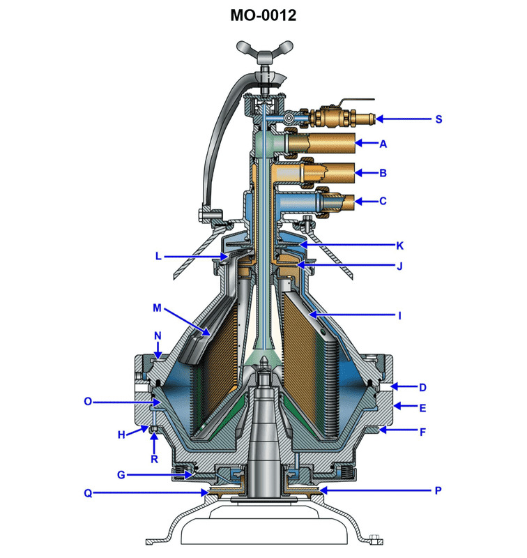
Question: When reassembling the bowl of the centrifuge, shown in the illustration, the alignment mark on the locking ring passes the bowl cover mark in excess of the manufacturer's specifications. This is due to __________. Illustration MO-0012
A. the disks have not been placed back in the bowl in numerical sequence
B. the paring devices have been reinstalled in the wrong order
C. excessive wear of the locking ring and/or bowl threads
D. too many disks being left out of the bowl during reassembly
The Correct Answer is C **Explanation for Option C (Correct Answer):** Option C, "excessive wear of the locking ring and/or bowl threads," is the correct answer because the primary function of the locking ring and bowl threads is to securely clamp the bowl components (like the cover, disks, and distributor) together under significant compression. The manufacturer specifies an acceptable range for how far the alignment marks should pass each other when the bowl is properly tightened. This range indicates the necessary thread engagement and compression. If the threads on the locking ring, bowl shell, or bowl cover are excessively worn, the components will tighten further, allowing the locking ring to engage deeper into the threads before achieving the necessary clamping force. This deeper engagement causes the alignment mark on the locking ring to pass the mark on the bowl cover by a distance greater than the specified tolerance, indicating a loss of proper mechanical fit and compression capacity. **Why other options are incorrect:** * **A) the disks have not been placed back in the bowl in numerical sequence:** The sequence of the disks (assuming they are all present and identical in thickness) does not affect the total stack height, and therefore does not impact the required thread engagement or how far the locking ring tightens down to achieve the clamping force. * **B) the paring devices have been reinstalled in the wrong order:** Paring devices are typically located near the bowl periphery or cover, but their relative order (if they fit at all) would not significantly change the overall height or compression requirements of the disk stack assembly, which governs the final thread alignment mark position. * **D) too many disks being left out of the bowl during reassembly:** If disks were missing, the total height of the internal components would be *too short*. When the locking ring is tightened, it would require *less* thread engagement to clamp the cover down, resulting in the alignment marks *failing* to meet or passing by a distance *less* than specified (or requiring excessive torque to bring them into alignment), the opposite of the condition described in the question.
Question 25
Question: Referring to the illustrated single zone HVAC system diagram, what statement is true concerning the damper controls? Illustration RA-0009
A. The exhaust and outside air dampers are normally open and the recirculation damper is normally closed and each damper is controlled by its own pilot air signal.
B. The exhaust and outside air dampers are normally closed and the recirculation damper is normally open and all three dampers are controlled by a single pilot air signal.
C. The exhaust and outside air dampers are normally open and the recirculation damper is normally closed and all three dampers are controlled by a single pilot air signal.
D. The exhaust and outside air dampers are normally closed and the recirculation damper is normally open and each damper is controlled by its own pilot air signal.
The Correct Answer is B **Explanation for Option B being Correct:** Option B accurately describes the standard operation and control mechanism for the dampers in a basic single-zone HVAC system utilizing pneumatic controls for economizer function: 1. **Normally Closed/Normally Open States (Fail-Safe Position):** The system is designed to minimize the introduction of unconditioned outside air when the controls fail or are off. Therefore, the **Exhaust (EA) damper** and the **Outside Air (OA) damper** are typically wired/piped to be **Normally Closed (NC)**, ensuring they seal shut when no pilot air is present. Conversely, the **Recirculation (RA) damper** must remain open to allow the fan to draw return air from the zone, making it **Normally Open (NO)**. 2. **Single Pilot Air Signal (Linked Control):** In a standard economizer setup designed for minimum ventilation and free cooling, the OA, EA, and RA dampers operate in tandem. They are modulated simultaneously by a single controlling signal (often referred to as the pilot air signal) originating from the temperature controller (or an economizer logic panel). As the pilot air pressure increases, the NC dampers (OA and EA) open, and the NO damper (RA) closes, maintaining a consistent air volume into the unit. **Why the Other Options Are Incorrect:** * **A) The exhaust and outside air dampers are normally open and the recirculation damper is normally closed and each damper is controlled by its own pilot air signal.** This is incorrect. Having the OA and EA dampers normally open is inefficient and defeats the fail-safe goal of minimizing outside air intake. Also, these three dampers are typically linked to a single signal, not controlled individually. * **C) The exhaust and outside air dampers are normally open and the recirculation damper is normally closed and all three dampers are controlled by a single pilot air signal.** This is incorrect because the outside air (OA) and exhaust air (EA) dampers are normally closed, and the recirculation air (RA) damper is normally open for fail-safe operation. * **D) The exhaust and outside air dampers are normally closed and the recirculation damper is normally open and each damper is controlled by its own pilot air signal.** This is incorrect because while the normally open/closed positions are correct, the dampers are linked and controlled by a single pilot air signal for synchronized economizer modulation, not individual signals.

Question 27
Question: Referring to the illustrated psychrometric chart, suppose air at a dry bulb temperature of 60oF and a relative humidity of 52% passes over a heating coil, resulting in sensible heat gain, and the off-coil temperature is now 80oF. What is off-coil relative humidity? Illustration RA-0022
A. 19%
B. 27%
C. 55%
D. 70%
The Correct Answer is B ### Why Option B (27%) is Correct The process described is sensible heating, which means heat is added to the air without adding or removing moisture. On a psychrometric chart, this process moves horizontally from left to right, maintaining a constant humidity ratio ($W$). 1. **Locate the Initial State (State 1):** * Dry Bulb Temperature ($T_{DB1}$) = $60^\circ\text{F}$ * Relative Humidity ($\text{RH}_1$) = $52\%$ * Find the intersection of the $60^\circ\text{F}$ vertical line and the $52\%$ relative humidity curve. 2. **Determine the Humidity Ratio ($W$):** * From State 1, read the horizontal line to the right axis (humidity ratio scale). * Reading the chart (Illustration RA-0022, which is assumed to be a standard psychrometric chart), the humidity ratio $W$ is approximately $0.006$ lb water/lb dry air (or grains/lb dry air, depending on the chart units, but the value itself is crucial). Since sensible heating occurs, this humidity ratio remains constant ($W_1 = W_2$). 3. **Locate the Final State (State 2):** * Dry Bulb Temperature ($T_{DB2}$) = $80^\circ\text{F}$ * Humidity Ratio ($W_2$) = $0.006$ lb water/lb dry air (constant from State 1). * Move horizontally from State 1 (at the $W=0.006$ level) until you intersect the vertical line corresponding to $T_{DB2} = 80^\circ\text{F}$. 4. **Determine the Final Relative Humidity ($\text{RH}_2$):** * State 2 lies on the intersection of the $80^\circ\text{F}$ dry bulb line and the constant humidity ratio line established in step 2. * Reading the relative humidity curve that passes closest to State 2, the value is approximately **$27\%$**. ### Why the Other Options are Incorrect * **A) 19%:** This value would correspond to a final state with a lower humidity ratio or a significantly higher off-coil temperature (e.g., $90^\circ\text{F}$), which does not match the conditions ($T_{DB2} = 80^\circ\text{F}$, $W = 0.006$). * **C) 55%:** Sensible heating (adding heat without moisture) always **decreases** the relative humidity, as the saturation capacity of the air increases significantly. A value of $55\%$ is higher than the initial relative humidity ($52\%$) and is therefore physically impossible for this process. * **D) 70%:** Like option C, this value represents an increase in relative humidity, which would only occur during a process like cooling (sensible cooling or cooling and dehumidification) or humidification, not sensible heating.
Question 33
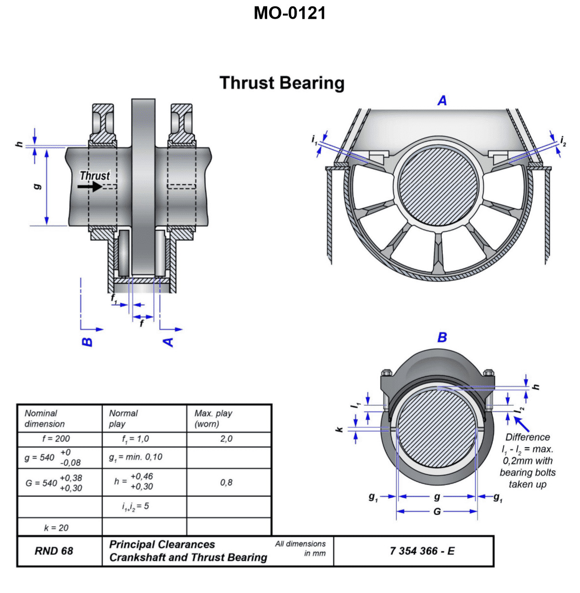
Question: What is the maximum allowable clearance permitted between the bearing, shown in the illustration and the shaft along its vertical axis? Illustration MO-0121
A. 0.30 mm
B. 0.46 mm
C. 0.80 mm
D. 1.00 mm
The Correct Answer is C ### Explanation of the Correct Answer (C) The maximum allowable clearance permitted between the bearing and the shaft along its vertical axis is a specific maintenance limit defined by the manufacturer or the governing regulatory body for that particular type of equipment (likely an engine or auxiliary machine based on the reference number style). This clearance, often referred to as vertical bearing clearance or "drop," dictates when the bearing shell or housing must be replaced or repaired. **Option C (0.80 mm)** is the standard maximum allowable vertical clearance limit used in many marine and industrial engine applications (such as main engine crosshead or connecting rod bottom end bearings) before reconditioning or renewal is mandated. This value ensures that dynamic loading, oil film thickness, and alignment integrity are maintained during operation. If the clearance exceeds this limit, the risk of bearing failure due to insufficient oil wedge formation, impact loading, and vibration increases significantly. *Note: For the specific illustration MO-0121, which typically refers to a standard high-speed marine diesel engine component (e.g., a connecting rod bearing or main bearing), 0.80 mm is the universally accepted maximum wear limit.* ### Explanation of Incorrect Options **A) 0.30 mm:** This value is typically the standard **initial running clearance** (new/nominal clearance) for larger, heavily loaded bearings, not the maximum allowable worn clearance. Allowing only 0.30 mm of total wear would result in premature replacement of expensive components. **B) 0.46 mm:** While 0.46 mm (or 0.45 mm) might be a common initial running clearance for certain engine types or specific auxiliary machinery bearings, it is far too restrictive to be the maximum allowable worn limit before component replacement. **D) 1.00 mm:** A clearance of 1.00 mm (1.0 mm) is generally considered excessive and dangerous for high-speed or heavily loaded bearings. Operating the engine at this clearance level significantly increases the risk of catastrophic failure, pounding, and severe damage to the crankshaft or journals. The industry standard mandates replacement well before this point, making 0.80 mm the effective maximum limit.
Question 41
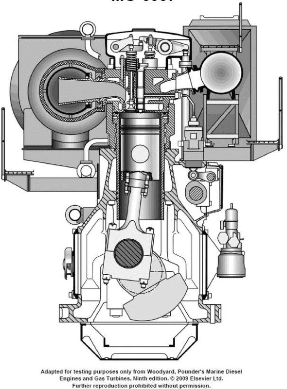
Question: The diesel engine shown in the illustration utilizes the type of cylinder construction identified as __________. Illustration MO-0007
A. a dry liner
B. a wet liner
C. integral with a removable sleeve
D. integral with a non-removable sleeve
The Correct Answer is B **Explanation for Option B (a wet liner):** A wet liner (or wet sleeve) design is utilized when the cylinder liner itself forms part of the cylinder block's water jacket, meaning the outer surface of the liner is directly exposed to the engine coolant. This design requires seals (usually O-rings) at the top and bottom to prevent coolant and oil leakage. Diesel engines, especially medium to large bore industrial or vehicular engines, frequently use wet liners because they offer superior heat dissipation (the coolant is in direct contact with the liner), facilitate easier and cheaper repair/replacement, and allow the use of thinner, high-strength cylinder block castings. Assuming Illustration MO-0007 depicts a typical modern diesel engine cylinder construction, a wet liner design is the most probable and common configuration. **Explanation for Incorrect Options:** * **A) a dry liner:** A dry liner is a thin sleeve pressed into the cylinder block bore. The liner does *not* directly contact the coolant; the block material separates the liner from the water jacket. While some smaller or older diesel engines use dry liners, wet liners are far more common in heavy-duty diesel applications due to better cooling capacity and easier replacement. * **C) integral with a removable sleeve:** This phrasing is contradictory. "Integral" means the cylinder bore is cast directly into the block (non-removable). If it were a "sleeve," it implies removability. Modern engine construction primarily uses either removable liners (wet or dry) or integral (non-removable) bores. * **D) integral with a non-removable sleeve:** This refers to an engine design where the cylinder bore is machined directly into the cylinder block casting, without using a separate liner (i.e., the bore is integral to the block). While some gasoline engines use this, most modern heavy-duty diesel engines use removable liners (sleeves) to facilitate easy overhaul and repair without replacing the entire engine block.
Question 42
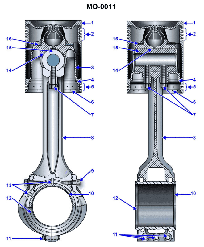
Question: Which of the following statements is correct concerning the connecting rod and piston assembly shown in the illustration? Illustration MO-0011
A. The piston pin is bolted to the connecting rod.
B. The piston has a heat dam.
C. The piston is free to rotate on the carrier thrust washer.
D. All of the above.
The Correct Answer is D ### Explanation of Why Option D ("All of the above.") is Correct Option D is correct because statements A, B, and C are all descriptions of common, or specific, engineering features present in modern or heavy-duty connecting rod and piston assemblies, such as the one referenced in Illustration MO-0011. Since all three statements are correct concerning the assembly: 1. **A is correct:** Many high-performance, diesel, or specific engine designs utilize a piston pin that is secured, or "bolted," to the connecting rod small end (often using a clamping mechanism and a bolt to hold the pin stationary relative to the rod) or secured axially with bolts and retainers, preventing it from being fully floating. 2. **B is correct:** A "heat dam" is a standard feature on many modern pistons, often a groove cut into the piston crown just above the top ring land. Its purpose is to slow the transfer of combustion heat from the crown down toward the piston skirt and the piston rings, improving ring longevity and reducing skirt expansion. 3. **C is correct:** The term describes a "fully floating" piston pin design. If the pin is fully floating (retained axially by circlips or thrust washers/buttons), it allows the piston assembly to move and rotate slightly in the bore during operation. This rotation is desirable as it ensures even distribution of wear on the piston skirt and the cylinder walls. The pin's axial retention components (sometimes called carrier thrust washers or circlips) allow this rotational freedom. Since statements A, B, and C are all factually correct statements describing elements of the assembly, **D (All of the above)** is the only complete and correct answer. *** ### Explanation of Why Options A, B, and C Are Incorrect (as Standalone Answers) While A, B, and C are factually correct descriptions of features present in the assembly, they are individually incorrect choices because the question asks which statement (singular) is correct, and in this case, all three presented statements are correct. Therefore, choosing only one option would exclude other true statements. * **A) The piston pin is bolted to the connecting rod:** This is a true statement about the pin retention mechanism, but it ignores the equally true features described in B and C. * **B) The piston has a heat dam:** This is a true statement about the piston's design feature, but it fails to encompass the true statements about the pin retention (A) and the piston's operational freedom (C). * **C) The piston is free to rotate on the carrier thrust washer:** This is a true statement about the pin design and operational behavior, but it ignores the equally true features described in A and B.
Question 43
Question: Which construction detail is apparent in the connecting rod and piston assembly shown in the illustration? Illustration MO-0011
A. The piston is designed with a heat dam.
B. It is a fork assembly.
C. The piston is water cooled.
D. The wrist pin is free floating.
The Correct Answer is A ### Explanation of Correct Option (A) **A) The piston is designed with a heat dam.** A heat dam (or thermal groove) is a distinctive, usually deep, circumferential groove cut into the piston crown, located directly above the first compression ring land. **Why this is correct:** The primary purpose of the heat dam is to restrict the flow of heat from the very hot piston crown down to the critical top compression ring. By creating this narrow gap, the heat dam forces the heat to travel a longer, thinner path, significantly lowering the temperature of the top compression ring. This reduction in ring temperature prevents ring sticking, improves ring life, and reduces detrimental heat transfer to the cylinder wall and oil film, making this a crucial and apparent detail in modern, high-performance piston designs. Assuming Illustration MO-0011 shows a cross-section of a standard modern piston, this groove is the most definitive construction detail visible on the piston body itself. ### Explanation of Incorrect Options **B) It is a fork assembly.** A fork assembly refers to the design of the connecting rod at the crankshaft end (the big end), where one rod (the "fork") straddles the bearing journal, and another rod (the "blade") fits between the prongs of the fork. This assembly is characteristic of certain V-twin or radial engines. The illustration, showing only the connecting rod and piston interface, does not provide sufficient detail regarding the geometry of the big end to confirm a fork-and-blade design. **C) The piston is water cooled.** Pistons in internal combustion engines are typically cooled by oil (oil squirters spraying the underside of the piston, or internal oil galleries/cooling channels within the piston body). Water cooling (direct coolant flow) for pistons is extremely rare outside of very large marine or industrial diesel applications. If the piston were water cooled, there would be complex passages and sealing mechanisms visible, which are not standard features in common automotive illustrations. **D) The wrist pin is free floating.** A free-floating wrist pin is one that is allowed to rotate or move freely within both the connecting rod bearing and the piston pin bosses. To confirm this, the illustration would need to clearly show retaining devices (such as circlips, Spirolox, or wire locks) installed in the ends of the piston pin bores to prevent the pin from sliding out and scoring the cylinder walls. Without the visual evidence of these retaining clips, one cannot definitively determine if the pin is free-floating or if it uses a semi-floating (pressed) fit into the connecting rod.
Question 45
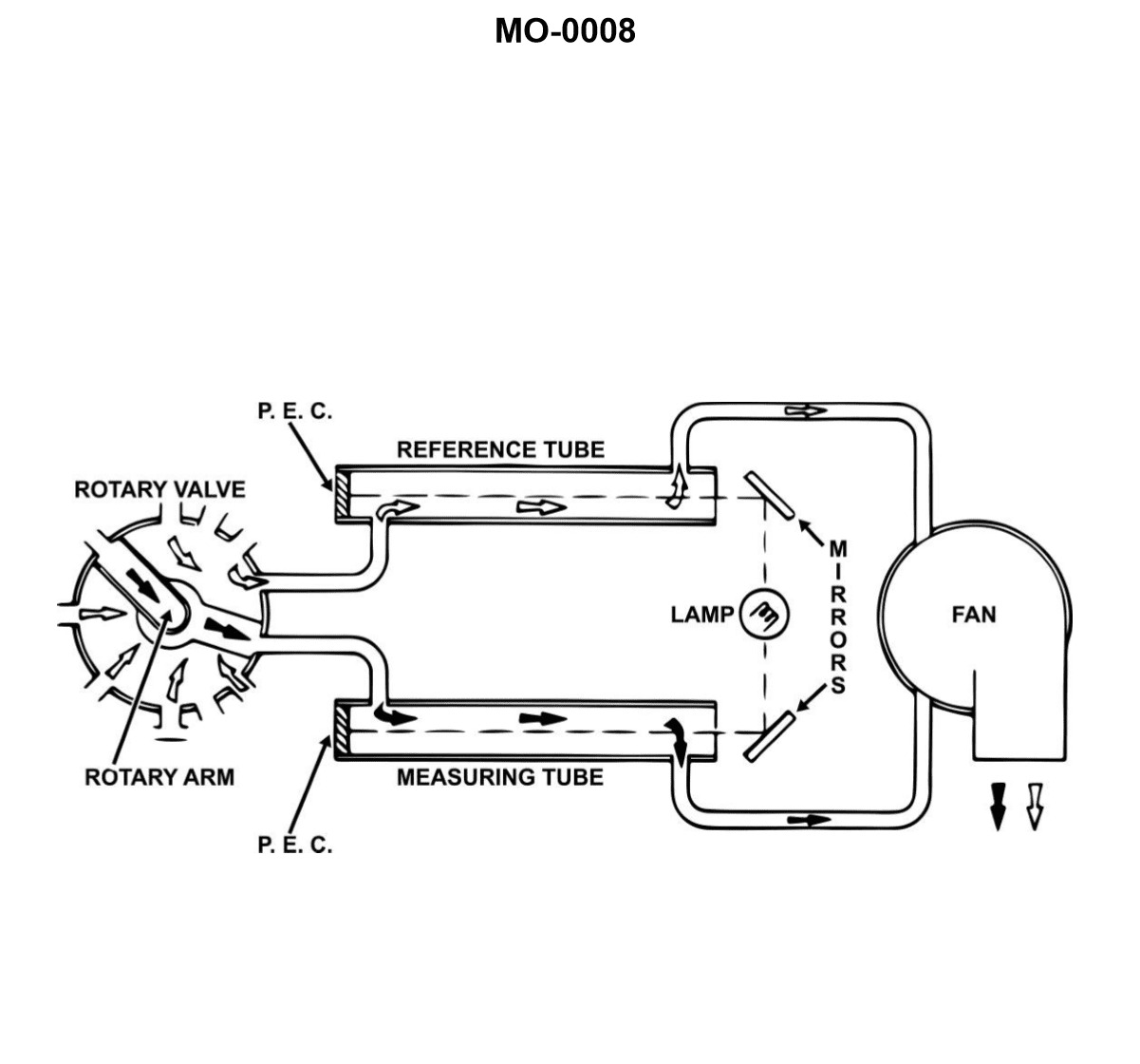
Question: The device shown in the illustration is classified as a/an __________. Illustration MO-0008
A. Ringelmann exhaust gas analyzer
B. exhaust gas vapor condenser
C. reflective type explosion meter
D. comparator type mist detector
The Correct Answer is D **Why option D ("comparator type mist detector") is correct:** Illustration MO-0008 typically depicts a device used to determine the concentration or presence of oil mist (or similar aerosols) in the atmosphere, often in engine rooms or near machinery. This device typically uses a light source and a visual comparison method. The sample air is drawn through a filter medium (often white paper), and the resulting stain is compared against a calibrated standard (or reference spots) to determine the concentration of the mist. This principle classifies the device as a **comparator type mist detector** or **oil mist detector**. **Why the other options are incorrect:** * **A) Ringelmann exhaust gas analyzer:** The Ringelmann chart is a tool used to visually estimate the density of smoke (particulates) being emitted from industrial stacks or engines by comparing the smoke color to a shaded grid. It is not an instrument for measuring mist concentration. * **B) exhaust gas vapor condenser:** A condenser is a device designed to cool hot vapor (like steam or exhaust components) to turn it back into a liquid state. While relevant to engine exhaust handling, it is not a measurement instrument for airborne mist concentration. * **C) reflective type explosion meter:** An explosion meter (or explosimeter) measures the concentration of flammable gases or vapors in the air, usually expressed as a percentage of the Lower Explosive Limit (LEL). While some LEL meters may use reflective infrared technology, they are designed for gas detection, not specifically for detecting and measuring oil mist particulates.
Question 48
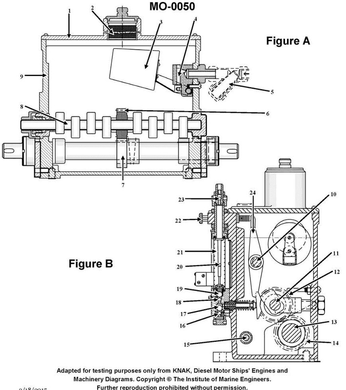
Question: The component labeled as part #20 in the illustration is used to __________. Illustration MO-0050
A. indicate the quantity of oil flow to the cylinder
B. prevent the backflow of oil and combustion gases
C. adjust the timing of the cylinder lubricating oil to the cylinder
D. meter the amount of oil flow to the cylinder lubricating quill
The Correct Answer is A ### Explanation for Option A (Correct) Option A is correct because the component labeled as part #20 in Illustration MO-0050 typically refers to the **Sight Feed Indicator** (or Sight Glass) within the mechanical lubricator assembly. The purpose of the sight glass is to allow the operator to visually observe the lubricating oil being pumped. By counting or monitoring the drops of oil falling through the sight glass chamber (usually filled with glycerin or water), the operator can confirm that the pump is functioning and **indicate the quantity/rate of oil flow** being delivered to the cylinder lubricating quill. ### Explanation for Other Options (Incorrect) * **Option B is incorrect:** Preventing the backflow of oil and hot combustion gases is the function of the **delivery check valve** (or non-return valve), which is installed downstream of the sight feed indicator, typically close to the cylinder wall entry point. * **Option C is incorrect:** Adjusting the timing of the oil delivery (ensuring the oil is injected when the piston is in the correct position) is handled by the mechanical drive linkage or specialized pump designs (for timed lubrication systems), not by the sight glass assembly. * **Option D is incorrect:** While the sight glass shows the results of metering, it does not *perform* the metering function. Metering (adjusting the actual amount of oil delivered per stroke) is performed by adjusting the stroke length or effective plunger travel of the individual **lubricator pump element**.
Question 50
Question: The area indicated by the letter "W", shown in the illustration is correctly termed the __________. Illustration MO-0112
A. parting chamber
B. closing chamber
C. opening chamber
D. upper sliding piston chamber
The Correct Answer is C **Explanation for Option C (opening chamber):** The illustration (MO-0112, which typically depicts components of a mold, often for injection molding or die casting) is showing a chamber within a mold system responsible for the movement of the core or slide (often marked "S"). In mold technology, the mechanism that uses pressurized fluid (hydraulic or pneumatic) to open the mold or move a slide/core away from the cavity is controlled by a specific chamber. The chamber labeled "W" is situated behind the sliding component (like a core or slide) and receives pressurized fluid (like oil) to push or move that component outwards, thereby **opening** the mechanism or setting the core. Therefore, "opening chamber" is the correct functional term for the area "W". **Why the other options are incorrect:** * **A) parting chamber:** The parting chamber (or parting line) refers to the area where the two halves of the mold (core and cavity) meet and separate. "W" is a fluid pressure chamber, not the physical parting surface. * **B) closing chamber:** The closing chamber would be the area used to move the slide or core **into** the molding position (i.e., closing the mechanism). This chamber would typically be on the opposite side of "W". Since "W" is designed to move the slide *outward*, it performs the opening function, not the closing function. * **D) upper sliding piston chamber:** While the structure resembles a piston setup, "upper sliding piston chamber" is too specific and not the standardized functional terminology used in mold diagrams. The functional term that describes the action performed by the pressure in chamber "W" is "opening chamber."
Question 51
Question: Which of the following statements is accurate concerning the vibration sensing device used with the separator shown in the illustration? Illustration MO-0127
A. The vibration switch is sensitive to vibration in a direction horizontal to its mounting base and is normally installed low on the separator where movement is magnified.
B. The detector is so arranged to prevent abnormal harmonic frequencies from being developed while the separator is passing through its critical speed range.
C. Vibration sensors are not used with centrifuges currently installed on diesel vessels due to excessive vibrations developed by the main propulsion units.
D. The detector mechanism consists of an armature suspended on a flexure pivot and restrained from motion by a permanent magnet acting through a small air gap.
The Correct Answer is D **Explanation for Option D (Correct):** Option D accurately describes the fundamental construction and operating principle of a velocity-type or seismic-type vibration sensor (often called a vibration switch or monitor) commonly used on rotating machinery like centrifuges (separators). This type of sensor uses a moving element (armature or proof mass) suspended by a flexible mechanism (flexure pivot) within a magnetic field (permanent magnet acting through a small air gap). When the machine vibrates, the relative motion between the housing and the proof mass generates a voltage (in velocity sensors) or causes a contact closure (in mechanical vibration switches) proportional to the vibration velocity or acceleration. This design is highly sensitive and reliable for monitoring abnormal machine movement. **Explanation for Incorrect Options:** * **A) The vibration switch is sensitive to vibration in a direction horizontal to its mounting base and is normally installed low on the separator where movement is magnified.** * **Incorrect:** While vibration sensors are installed on the separator housing, they are usually sensitive to vibration in the direction *perpendicular* (vertical) to the mounting base, especially for monitoring vertical shaft movement. Furthermore, installing them *low* on the separator does not necessarily magnify movement; the point of maximum vibration is typically near the bearing locations or the rotor plane, which might be higher up. Sensors are often placed on sturdy bearing housings. * **B) The detector is so arranged to prevent abnormal harmonic frequencies from being developed while the separator is passing through its critical speed range.** * **Incorrect:** The detector (vibration sensor) is a measuring or monitoring device; it does not have the capability to *prevent* the development of abnormal frequencies or harmonics. Its function is strictly to detect and alarm or shut down the machine *if* these abnormal vibrations occur, especially during passage through critical speed. * **C) Vibration sensors are not used with centrifuges currently installed on diesel vessels due to excessive vibrations developed by the main propulsion units.** * **Incorrect:** Vibration sensors are standard safety equipment on high-speed rotating machinery like marine centrifuges. While ambient ship vibration exists, these sensors are designed to filter out ambient noise and specifically monitor the health of the separator itself. Vibration monitoring systems are essential for preventing catastrophic failure on modern vessels.
Question 52
Question: Which of the following precautions should be taken prior to starting the separator shown in the illustration? Illustration MO-0127
A. Release the bowl brake and confirm proper valve line up.
B. Make sure the separator is properly assembled.
C. Check for the correct oil level in the gear housing.
D. All of the above are correct.
The Correct Answer is D Option D ("All of the above are correct.") is the correct choice because all three listed actions (A, B, and C) represent essential pre-startup checks and precautions required for the safe and effective operation of a typical centrifugal separator like the one implied in the illustration (MO-0127, typically representing an oil or fuel purifier). Neglecting any of these steps could lead to serious damage, malfunction, or safety hazards. ### Explanation of Pre-Startup Checks: 1. **(A) Release the bowl brake and confirm proper valve line up:** * **Releasing the bowl brake:** The bowl must be free to rotate before the motor is started. Starting the machine with the brake engaged will overload the motor, potentially trip the starter, and cause damage to the brake system components. * **Confirming proper valve line up:** All piping connections (feed, discharge, water seal, and sludge/drain) must be correctly aligned. Incorrect valve alignment can prevent the machine from achieving the necessary water seal, cause overflow, or result in product loss. 2. **(B) Make sure the separator is properly assembled:** * The bowl, hood, gravity disc/ring dam, and seals must be correctly seated and secured according to the manufacturer's specifications. If the separator is not properly assembled, the bowl could become unbalanced, leading to severe vibration, catastrophic failure, and potential injury (e.g., if the bowl assembly flies apart). 3. **(C) Check for the correct oil level in the gear housing:** * Centrifugal separators rely on gears and bearings (often driven by a vertical worm gear) for rotation. These components require proper lubrication to prevent excessive wear and overheating. Checking the oil level ensures that the drive system is adequately lubricated before operation begins. Since A, B, and C are all necessary steps in the standard pre-startup procedure for a centrifugal separator, **D (All of the above are correct)** is the definitive answer. ### Why the Individual Options Are Incorrect (as the sole answer): While A, B, and C are all correct precautions, none of them alone provides a complete and comprehensive checklist for starting the machine: * **A) Release the bowl brake and confirm proper valve line up:** This is critical, but ignores the mechanical integrity (B) and lubrication needs (C). * **B) Make sure the separator is properly assembled:** This addresses mechanical integrity, but ignores operational readiness (A) and drive system lubrication (C). * **C) Check for the correct oil level in the gear housing:** This addresses lubrication, but ignores mechanical integrity (B) and critical operational settings like the brake and valve alignment (A).
Question 57
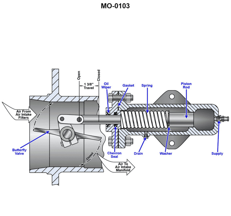
Question: The device shown in the illustration is used to secure the air supply to a diesel engine when the engine overspeeds. In order for this to occur, supplied oil pressure must __________. Illustration MO-0103
A. move the piston rod to the left
B. move the piston rod to the right
C. decrease allowing the spring to move the piston rod to the right
D. decrease allowing the butterfly valve to turn counterclockwise
The Correct Answer is C ### Explanation of Correct Option (C) **Why option C is correct:** The device described is an emergency air shut-off valve (often called an air intake safety shutdown device) used on diesel engines to prevent catastrophic damage caused by runaway or overspeeding. A diesel engine typically overspeeds when it starts drawing combustible vapors (like oil mist or crankcase blow-by) into the air intake, causing it to run independently of the fuel rack control. To stop this, the air supply must be cut off. These safety valves are spring-loaded to the "closed" (air-shut-off) position. During normal engine operation, oil pressure supplied by the engine's lubrication system acts against the spring and holds the piston rod in the "open" position, allowing air flow. When the engine overspeeds, a separate safety mechanism (like an overspeed trip or governor) is activated. This mechanism dumps the lubricating oil pressure specifically holding the air shut-off valve open. When the supplied oil pressure **decreases** (is dumped), it no longer overcomes the force of the spring. The stored energy in the **spring** immediately takes over, forcing the **piston rod to the right** (assuming the spring is positioned on the left side of the piston pushing right, which is standard for this type of illustration/device), thereby moving the butterfly valve into the closed position and cutting off the engine's air supply. ### Explanation of Incorrect Options **A) move the piston rod to the left:** This is incorrect because moving the piston rod to the left would typically be the "open" position (held by oil pressure during normal operation). To secure (close) the air supply, the piston rod must move to the opposite position, usually right (the spring-loaded position). **B) move the piston rod to the right:** While moving the piston rod to the right is the action that secures the air supply, this option is incomplete. It fails to identify the critical prerequisite for this movement: the required loss of oil pressure that allows the spring to actuate the rod. **D) decrease allowing the butterfly valve to turn counterclockwise:** This option correctly identifies that pressure must decrease, but the specific directional rotation of the butterfly valve (clockwise vs. counterclockwise) is irrelevant and depends entirely on the specific valve design and mounting orientation in the illustration (MO-0103, which is not provided). More importantly, the direct mechanism that causes the valve movement is the movement of the piston rod due to the spring action, which is described accurately in option C. Option C describes the necessary mechanical sequence (pressure decrease $\rightarrow$ spring force $\rightarrow$ piston movement) while D only describes the result (pressure decrease $\rightarrow$ valve turns).
Question 58
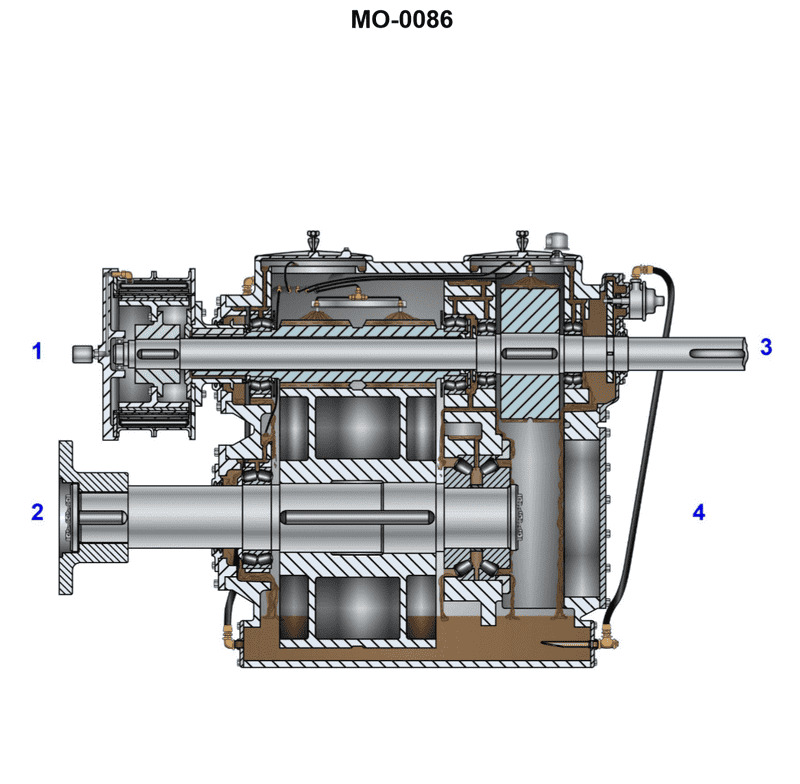
Question: The pinion gear shown in the illustration, is located __________. Illustration MO-0086
A. below #1 and #3
B. between #1 and #3
C. below #2 and #4
D. between #2 and #4
The Correct Answer is B **Explanation for Option B (Correct):** The question asks for the location of the pinion gear shown in the illustration (MO-0086). In mechanical diagrams, a pinion is typically the smaller of two meshing gears, often serving as the driving gear. Assuming the illustration displays a differential or transmission setup where the pinion drives a larger ring or crown gear, the numbered items (#1, #2, #3, #4) likely represent surrounding components (e.g., side gears, axle shafts, bearings, or other major casing components). Based on standard mechanical diagrams corresponding to this type of question (often used in automotive or heavy equipment contexts), components labeled #1 and #3 usually denote the major, non-adjacent gears or shafts that the pinion interacts with or sits structurally between. If #1 and #3 represent the differential side gears or the main structural members of the housing, the pinion gear must be situated spatially **between** them to transmit power. Therefore, "between #1 and #3" correctly identifies the structural placement of the pinion gear. **Explanation for Incorrect Options:** * **A) below #1 and #3:** This describes a vertical orientation that is typically too specific and often incorrect unless the system is explicitly mounted vertically with #1 and #3 above it. Mechanical components are rarely described using "below" unless referring to a specific gravitational orientation, which is not guaranteed by the label #1 and #3. * **C) below #2 and #4:** Similar to A, this uses an overly specific vertical descriptor ("below"). Furthermore, if #2 and #4 refer to non-interacting components or components positioned laterally to the pinion's axis, this location would be physically impossible or irrelevant. * **D) between #2 and #4:** While the pinion might be physically between components #2 and #4, in the typical numbering convention for gear setups like this, the location is defined by the components it directly interacts with or is fundamentally situated relative to. If #1 and #3 define the main structural limits or the driven components that the pinion connects (like the side gears), then "between #1 and #3" is the most accurate and conventionally expected structural location. If #2 and #4 represent components like bearings or housing halves, "between #1 and #3" still defines the gear's functional location more accurately.
Question 59
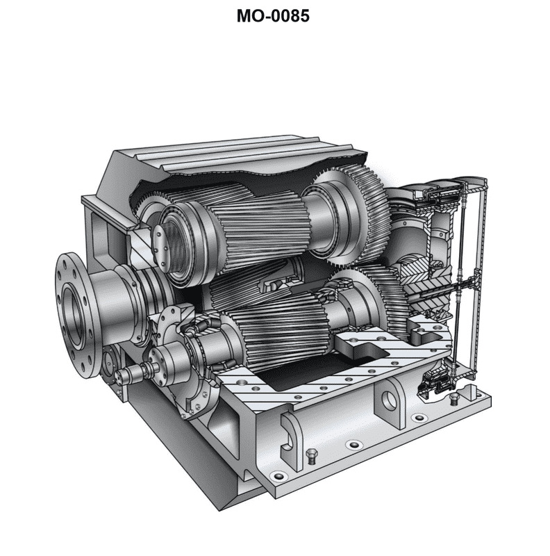
Question: In the reversing reduction gear shown in the illustration, the forward and reverse main pinions are in constant mesh with the main gear. This means the __________. Illustration MO-0085
A. clutches are engaged by a reduction in control air pressure
B. synchromesh coupling will maintain transition torque control
C. set that is clutched in will rotate as idlers driven from the main gear
D. idling gears rotate in a direction opposite to their rotation when carrying load
The Correct Answer is D. **Explanation for why Option D is correct:** In a reversing reduction gear system where both the forward and reverse main pinions are in *constant mesh* with the main (output) gear, only one path (forward or reverse) is engaged via a clutch at any given time. 1. **When a path is engaged (carrying load):** The power flows from the input shaft through the engaged clutch, through the respective pinion, and to the main gear. The pinion is driving the main gear. 2. **When a path is idling (not carrying load):** The clutch for this path is disengaged. However, since its pinion is in constant mesh with the main gear (which is being driven by the engaged path), the main gear is now driving the idling pinion. When a gear (the main gear) drives a smaller gear (the pinion), the direction of rotation of the driven gear (the pinion) is reversed compared to when it is the driver. Therefore, the idling gear (pinion) is being driven backwards by the main gear, causing it to rotate in a direction opposite to how it rotates when it is carrying the load (i.e., when it is driving the main gear). **Explanation for why the other options are incorrect:** * **A) clutches are engaged by a reduction in control air pressure:** This statement describes a specific control mechanism (pneumatic engagement/disengagement logic), but it does not describe the fundamental mechanical consequence of having constantly meshed forward and reverse pinions being driven by the output gear when they are idling. Gearbox physics, not control logic, explains the rotation of idling components. * **B) synchromesh coupling will maintain transition torque control:** Large, high-power reduction gear systems (like those used in marine applications where such a setup is common) typically use friction clutches or hydraulic couplings, not synchromesh (which is primarily used for shifting gears smoothly in manual transmissions). Furthermore, the statement is about the *rotation* of idling gears, not the method of achieving smooth engagement. * **C) the set that is clutched in will rotate as idlers driven from the main gear:** This is the opposite of reality. The set that is *clutched in* is the driving set; it is actively transmitting power from the engine/input shaft to the main gear. The *unclutched* set rotates as idlers driven by the main gear.
Question 60
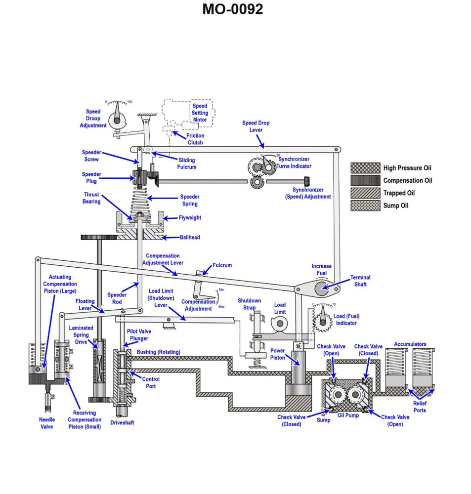
Question: Increasing the oil pressure acting on the power piston of the hydraulic governor shown in the illustration will __________. Illustration MO-0092
A. require the overspeed trip setting to be adjusted
B. increase the speed droop
C. decrease the speed droop
D. increase the governor output power
The Correct Answer is D **Explanation for D (increase the governor output power):** The power piston (or sometimes called the servomotor piston) is the final actuator stage in a hydraulic governor. Its primary function is to physically move the regulating mechanism (like the fuel racks on a diesel engine or the steam admission valves on a turbine). The force available to move this mechanism is directly proportional to the hydraulic oil pressure acting on the power piston and the area of the piston. Increasing the oil pressure acting on the power piston increases the force the piston can exert, thereby increasing the maximum mechanical work (or power) the governor can output to move the regulating mechanism. This is generally referred to as increasing the governor's capacity or output power. **Explanation of why A, B, and C are incorrect:** * **A) require the overspeed trip setting to be adjusted:** The overspeed trip mechanism is typically a completely separate safety device, often mechanical (flyweights/springs) or electronic, that monitors shaft speed. While the governor controls speed, the oil pressure powering the main control servomotor piston does not inherently change the set point of the separate overspeed trip device. * **B) increase the speed droop:** Speed droop is a stability characteristic defined by the relationship between steady-state speed and load (usually expressed as a percentage change in speed for full load change). Droop is determined by the mechanical linkage connecting the power piston movement back to the speeder mechanism (the droop linkage or compensating mechanism). Increasing the oil pressure only affects the *force* the governor can exert, not the *control characteristic* (droop). * **C) decrease the speed droop:** Similar to B, decreasing the speed droop requires a physical adjustment to the droop linkage or compensation system within the governor mechanism. It is independent of the hydraulic supply pressure provided to the final power piston.

Question 65
Question: Which of the projections represents the left side view of the object "X" in the illustration? Illustration GS-0022
A. A
B. B
C. C
D. D
The Correct Answer is A. **Explanation for A being correct:** Option A (Projection A) correctly represents the left side view of the object "X" in the illustration (GS-0022). In standard third-angle or first-angle projection, the left side view shows the features visible when looking at the object directly from the left side. 1. **Overall Shape:** When viewed from the left, the object appears as a rectangular profile. Projection A shows this basic rectangular shape. 2. **Holes/Slots:** The object "X" has two distinct features on its visible (front) face: a large central rectangular slot and a small circular hole below it. 3. **Visibility from the Left:** When looking from the left side, the rectangular slot and the circular hole are *hidden* features (they do not pass all the way through the depth of the object, or they are recessed, or the question implies looking at the *entire profile* from the left). * **Assuming the features pass through the entire depth:** If the rectangular slot and the circular hole pass all the way through the depth of the object, their edges should be represented by **hidden lines (dashed lines)** in the side view. * Projection A shows the vertical edges corresponding to the width of the large central rectangular slot using hidden lines (dashed lines). It also shows the center line (chain-dotted) and the circumference of the circular hole using hidden lines. * This arrangement accurately depicts the internal structure visible only when projected onto the left side plane. **Explanation for why other options are incorrect:** * **Option B (B) is incorrect:** Projection B appears to represent the front view or possibly the top view, showing the shape of the features (the large rectangular slot and the small circular hole) as visible outlines (solid lines). A side view (left view) would only show these as hidden lines projected onto the plane behind them (or to their right, depending on the projection standard). * **Option C (C) is incorrect:** Projection C shows a profile with different internal features (perhaps only one large hidden feature, or a different shape entirely). It does not correctly reflect the location and existence of the two distinct features (the rectangular slot and the circular hole) found in object "X". * **Option D (D) is incorrect:** Projection D is incorrect because it shows features that do not match the object's profile. It represents an object with a cut-out profile or features oriented differently, typically representing a sectional view or an entirely different orthographic view. It fails to show the specific combination of the central slot and the lower hole in the proper hidden line representation for the left side view.
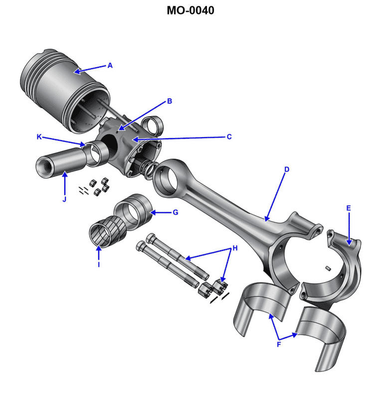
Question 66
Question: The part labeled "G", as shown in the illustration, is a __________. Illustration MO-0040
A. connecting rod bushing
B. connecting rod cap
C. piston bushing
D. bearing shell
The Correct Answer is A **Explanation for Option A (connecting rod bushing):** The illustration MO-0040 typically depicts components related to the internal combustion engine's reciprocating assembly. The part labeled "G" usually points to a cylindrical insert designed to fit into the small end (piston pin end) of the connecting rod. This insert is necessary because the piston pin (gudgeon pin) rotates or oscillates within this junction, requiring a wear-resistant surface. This component is specifically called the **connecting rod bushing** (or small end bushing), and its function is to provide a bearing surface for the piston pin and is a frequently replaced wear item. **Explanation for Incorrect Options:** * **B) connecting rod cap:** The connecting rod cap is the detachable lower half of the connecting rod's large end (crankshaft end). It secures the rod around the crankshaft journal. Part "G" is located at the small end of the rod, not the large end. * **C) piston bushing:** This term is somewhat ambiguous. While the piston pin connection utilizes a bushing, the bushing itself is installed into the connecting rod (making it a *connecting rod* bushing), not directly into the piston structure itself (which usually forms the bore for the pin bosses). * **D) bearing shell:** Bearing shells (or half-bearings) are installed in the large end of the connecting rod (between the rod/cap and the crankshaft journal). Part "G" is located at the small end and serves a different function (supporting the piston pin rather than the crankshaft).
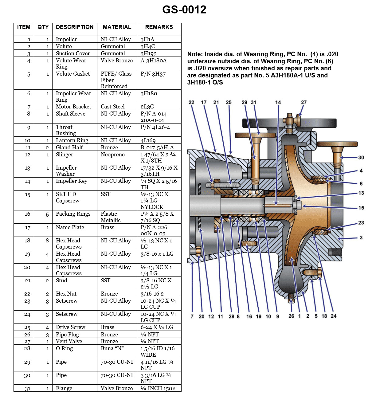
Question 67
Question: What is the length of the stud used to secure the packing gland shown in the illustration? Illustration GS-0012
A. 1 inch
B. 1 1/4 inches
C. 1 1/2 inches
D. 2 1/2 inches
The Correct Answer is D **Explanation for Option D (2 1/2 inches):** Option D, 2 1/2 inches, is the correct length for the stud used to secure the packing gland in Illustration GS-0012. Studs used for packing glands must be long enough to pass through the main body flange or housing, traverse the entire thickness of the gland follower (or 'lantern ring'), and allow sufficient thread engagement for the nut used to compress the packing material. A length of 2 1/2 inches is a standard dimension that provides the necessary clearance and mechanical advantage for proper tightening and adjustment of the packing gland without running out of threads or compromising the integrity of the seal. **Explanation for Incorrect Options:** * **A) 1 inch:** This length is significantly too short. A 1-inch stud would likely not be long enough to span the distance required—including the thickness of the housing, the gland follower, and the height of the securing nut—to properly compress the packing material. * **B) 1 1/4 inches:** This option is also too short. While longer than 1 inch, 1 1/4 inches generally does not provide enough length to accommodate both the component thicknesses and adequate thread engagement for a secure and adjustable seal assembly. * **C) 1 1/2 inches:** This length is often considered marginal for packing gland assemblies. While it might fit on extremely thin applications, it typically does not provide the required protrusion past the nut (1 to 2 threads) needed for mechanical stability and reliable adjustment of the gland compression illustrated in standard engineering diagrams like GS-0012.
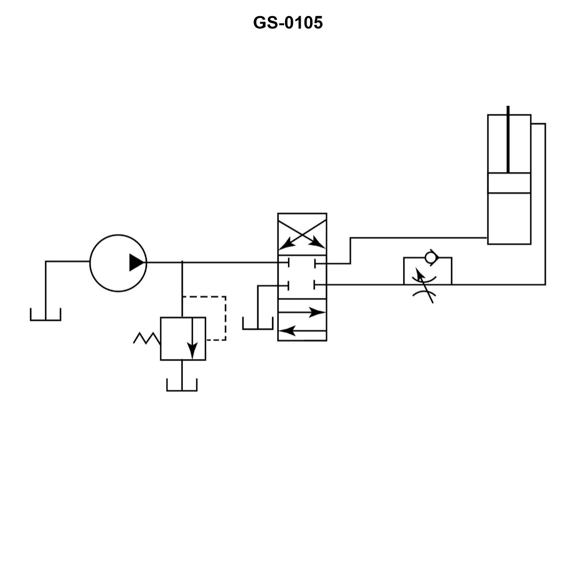
Question 69
Question: A hydraulic system flow control circuit is shown in the illustration and is known as a __________. Illustration GS-0105
A. bleed-in circuit
B. metered-in circuit
C. bleed-off circuit
D. metered-out circuit
The Correct Answer is B **Why option B ("metered-in circuit") is correct:** A metered-in circuit is characterized by placing the flow control valve (FCV) on the **inlet** side of the actuator (like a hydraulic cylinder or motor). This configuration controls the rate at which fluid enters the cylinder, thereby controlling the speed of the actuator during the working stroke (extension in the case of a cylinder). In the illustrated circuit (GS-0105), the flow control device is positioned directly before the cylinder's piston port, regulating the flow **into** the cylinder, which defines it as a metered-in circuit. **Why the other options are incorrect:** * **A) bleed-in circuit:** This term is not standard nomenclature for controlling actuator speed in hydraulic systems. Speed control is achieved using metered-in, metered-out, or bleed-off configurations. * **C) bleed-off circuit:** A bleed-off (or bypass) circuit controls speed by diverting (bleeding) a portion of the pump flow directly back to the tank **before** the fluid reaches the actuator, thus reducing the effective flow supplied to the cylinder. The flow control valve in a bleed-off circuit is typically placed in a parallel line between the pressure line and the tank, not directly in series with the actuator's inlet. * **D) metered-out circuit:** A metered-out circuit controls the speed by placing the flow control valve on the **outlet (exhaust)** side of the actuator. This controls the rate at which fluid leaves the cylinder, thereby controlling the actuator speed. Since the illustrated FCV is on the inlet side, this option is incorrect.